Exploring Scalable, Portable Docker Swarm Container Networks
Exploring Scalable, Portable Docker Swarm Container Networks
Introduction
Docker containers wrap a piece of software in a complete filesystem that contains everything needed to run: code, runtime, system tools, system libraries – anything that can be installed on a server. This guarantees that the software will always run the same, regardless of its environment. By default, containers isolate applications from one another and the underlying infrastructure, while providing an added layer of protection for the application.
What if the applications need to communicate with each other, the host, or an external network? How do you design a network to allow for proper connectivity while maintaining application portability, service discovery, load balancing, security, performance, and scalability? This Document is an overview of the architecture and design concepts with which to build and scale Docker container networks for both Linux and Microsoft servers.
Prerequisites
Before continuing, being familiar with Docker concepts and Docker Swarm is recommended:
Challenges of Networking Containers and Microservices
Microservices practices have increased the scale of applications which has put even more importance on the methods of connectivity and isolation provided to applications. The Docker networking philosophy is application driven. It aims to provide options and flexibility to the network operators as well as the right level of abstraction to the application developers.
Like any design, network design is a balancing act. Docker Enterprise and the Docker ecosystem provide multiple tools to network engineers to achieve the best balance for their applications and environments. Each option provides different benefits and tradeoffs. The remainder of this guide details each of these choices so network engineers can understand what might be best for their environments.
Docker has developed a new way of delivering applications, and with that, containers have also changed some aspects of how networking is approached. The following topics are common design themes for containerized applications:
- Portability
- How do I guarantee maximum portability across diverse network environments while taking advantage of unique network characteristics?
- Service Discovery
- How do I know where services are living as they are scaled up and down?
- Load Balancing
- How do I spread load across services as services themselves are brought up and scaled?
- Security
- How do I segment to prevent the wrong containers from accessing each other?
- How do I guarantee that a container with application and cluster control traffic is secure?
- Performance
- How do I provide advanced network services while minimizing latency and maximizing bandwidth?
- Scalability
- How do I ensure that none of these characteristics are sacrificed when scaling applications across many hosts?
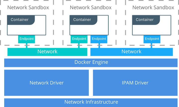
The Container Networking Model
The Docker networking architecture is built on a set of interfaces called the Container Networking Model (CNM). The philosophy of CNM is to provide application portability across diverse infrastructures. This model strikes a balance to achieve application portability and also takes advantage of special features and capabilities of the infrastructure.
CNM Constructs
There are several high-level constructs in the CNM. They are all OS and infrastructure agnostic so that applications can have a uniform experience no matter the infrastructure stack.
- Sandbox — A Sandbox contains the configuration of a container’s network stack. This includes the management of the container’s interfaces, routing table, and DNS settings. An implementation of a Sandbox could be a Windows HNS or Linux Network Namespace, a FreeBSD Jail, or other similar concept. A Sandbox may contain many endpoints from multiple networks.
- Endpoint — An Endpoint joins a Sandbox to a Network. The Endpoint construct exists so the actual connection to the network can be abstracted away from the application. This helps maintain portability so that a service can use different types of network drivers without being concerned with how it’s connected to that network.
- Network — The CNM does not specify a Network in terms of the OSI model. An implementation of a Network could be a Linux bridge, a VLAN, etc. A Network is a collection of endpoints that have connectivity between them. Endpoints that are not connected to a network do not have connectivity on a network.
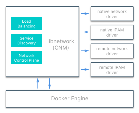
CNM Driver Interfaces
The Container Networking Model provides two pluggable and open interfaces that can be used by users, the community, and vendors to leverage additional functionality, visibility, or control in the network.
The following network drivers exist:
- Network Drivers — Docker Network Drivers provide the actual
implementation that makes networks work. They are pluggable so that
different drivers can be used and interchanged easily to support different
use cases. Multiple network drivers can be used on a given Mirantis
Container Runtime or Cluster concurrently, but each Docker network is only
instantiated through a single network driver. There are two broad types of
CNM network drivers:
- Native Network Drivers — Native Network Drivers are a native part of the Mirantis Container Runtime and are provided by Docker. There are multiple drivers to choose from that support different capabilities like overlay networks or local bridges.
- Remote Network Drivers — Remote Network Drivers are network drivers created by the community and other vendors. These drivers can be used to provide integration with incumbent software and hardware. Users can also create their own drivers in cases where they desire specific functionality that is not supported by an existing network driver.
- IPAM Drivers — Docker has a native IP Address Management Driver that provides default subnets or IP addresses for the networks and endpoints if they are not specified. IP addressing can also be manually assigned through network, container, and service create commands. Remote IPAM drivers also exist and provide integration to existing IPAM tools.
Docker Native Network Drivers
The Docker native network drivers are part of Mirantis Container Runtime and
don’t require any extra modules. They are invoked and used through standard
docker network commands. The following native network drivers exist.
| Driver | Description |
|---|---|
| Host | With the host driver, a container uses the networking stack of the
host. There is no namespace separation, and all interfaces on the host
can be used directly by the container. |
| Bridge | The bridge driver creates a Linux bridge on the host that is managed
by Docker. By default containers on a bridge can communicate with each
other. External access to containers can also be configured through the
bridge driver. |
| Overlay | The overlay driver creates an overlay network that supports
multi-host networks out of the box. It uses a combination of local Linux
bridges and VXLAN to overlay container-to-container communications over
physical network infrastructure. |
| Macvlan | The macvlan driver uses the Linux Macvlan bridge mode to establish a
connection between container interfaces and a parent host interface (or
sub-interfaces). It can be used to provide IP addresses to containers
that are routable on the physical network. Additionally VLANs can be
trunked to the macvlan driver to enforce Layer 2 container segmentation. |
| None | The none driver gives a container its own networking stack and
network namespace but does not configure interfaces inside the container.
Without additional configuration, the container is completely isolated
from the host networking stack. |
Network Scope
As seen in the docker network ls output, Docker network drivers have
a concept of scope. The network scope is the domain of the driver
which can be the local or swarm scope. Local scope drivers
provide connectivity and network services (such as DNS or IPAM) within
the scope of the host. Swarm scope drivers provide connectivity and
network services across a swarm cluster. Swarm scope networks have the
same network ID across the entire cluster while local scope networks
have a unique network ID on each host.
$ docker network ls
NETWORK ID          NAME                DRIVER              SCOPE
1475f03fbecb        bridge              bridge              local
e2d8a4bd86cb        docker_gwbridge     bridge              local
407c477060e7        host                host                local
f4zr3zrswlyg        ingress             overlay             swarm
c97909a4b198        none                null                local
Docker Remote Network Drivers
The following community- and vendor-created remote network drivers are compatible with CNM. Each provides unique capabilities and network services for containers.
| Driver | Description |
|---|---|
| contiv | An open source network plugin led by Cisco Systems to provide infrastructure and security policies for multi-tenant microservices deployments. Contiv also provides integration for non-container workloads and with physical networks, such as ACI. Contiv implements remote network and IPAM drivers. |
| weave | A network plugin that creates a virtual network that connects Docker containers across multiple hosts or clouds. Weave provides automatic discovery of applications, can operate on partially connected networks, does not require an external cluster store, and is operations friendly. |
| kuryr | A network plugin developed as part of the OpenStack Kuryr project. It implements the Docker networking (libnetwork) remote driver API by utilizing Neutron, the OpenStack networking service. Kuryr includes an IPAM driver as well. |
Docker Remote IPAM Drivers
Community and vendor created IPAM drivers can also be used to provide integrations with existing systems or special capabilities.
| Driver | Description |
|---|---|
| Infoblox | An open source IPAM plugin that provides integration with existing Infoblox tools. |
See also
There are many Docker plugins that exist and more are being created all the time. Docker maintains a list of the most common plugins.
Linux Network Fundamentals
The Linux kernel features an extremely mature and performant implementation of the TCP/IP stack (in addition to other native kernel features like VXLAN and packet filtering). Docker networking uses the kernel’s networking stack as low level primitives to create higher level network drivers. Simply put, Docker networking **is* Linux networking.*
This implementation of existing Linux kernel features ensures high performance and robustness. Most importantly, it provides portability across many distributions and versions, which enhances application portability.
There are several Linux networking building blocks which Docker uses to implement its native CNM network drivers. This list includes Linux bridges, network namespaces, veth pairs, and iptables. The combination of these tools, implemented as network drivers, provides the forwarding rules, network segmentation, and management tools for dynamic network policy.
The Linux Bridge
A Linux bridge is a Layer 2 device that is the virtual
implementation of a physical switch inside the Linux kernel. It forwards
traffic based on MAC addresses which it learns dynamically by inspecting
traffic. Linux bridges are used extensively in many of the Docker
network drivers. A Linux bridge is not to be confused with the
bridge Docker network driver which is a higher level implementation
of the Linux bridge.
Network Namespaces
A Linux network namespace is an isolated network stack in the kernel with its own interfaces, routes, and firewall rules. It is a security aspect of containers and Linux, used to isolate containers. In networking terminology they are akin to a VRF that segments the network control and data plane inside the host. Network namespaces ensure that two containers on the same host aren’t able to communicate with each other or even the host itself unless configured to do so via Docker networks. Typically, CNM network drivers implement separate namespaces for each container. However, containers can share the same network namespace or even be a part of the host’s network namespace. The host network namespace contains the host interfaces and host routing table.
Virtual Ethernet Devices
A virtual ethernet device or veth is a Linux networking
interface that acts as a connecting wire between two network namespaces.
A veth is a full duplex link that has a single interface in each
namespace. Traffic in one interface is directed out the other interface.
Docker network drivers utilize veths to provide explicit connections
between namespaces when Docker networks are created. When a container is
attached to a Docker network, one end of the veth is placed inside the
container (usually seen as the ethX interface) while the other is
attached to the Docker network.
iptables
iptables is the native packet filtering system that has been a
part of the Linux kernel since version 2.4. It’s a feature rich L3/L4
firewall that provides rule chains for packet marking, masquerading, and
dropping. The native Docker network drivers utilize iptables
extensively to segment network traffic, provide host port mapping, and
to mark traffic for load balancing decisions.
Microsoft Network Fundamentals
Networking in Windows 2016 and 2019
Docker Enterprise is supported on Windows version 2016 and above. Different network isolation mechanisms are available depending on the operating system version:
- In virtual machines (Windows 2016 only)
- Kernel based - native to the Windows operating system (default for 2019 and recommended)
In order to run Windows containers the following packages must be running:
- Windows Containers Feature
- Windows DockerMsftProvider Module
Both of these versions use similar networking features. Each container will include a virtual network adapter (vNIC) connected to a virtual switch. In the case of running Hyper-V to utilize containers this will be a Hyper-V switch. If using Microsoft native containers this will be a virtual switch created by the Host Networking Service (HNS) and attached to the primary physical nic (or vNIC in the case of virtual machines).
Windows Docker Network Drivers
Following a similar philosophy to the Linux architecture, Docker on Windows leverages operating system primitives to achieve robust policy with high throughput. Docker networking *is also Windows networking.* However, the underlying networking features differ between the two operating systems.
In addition te the overlay driver, Docker on Windows implements four
additional drivers:
- NAT (default)
- Transparent
- L2 Bridge
- L2 Tunnel
The following two tables summarize each Windows driver and the operating system features it consumes by pairing each Windows component with its functional equivalent in Linux.
| Docker Windows Network Driver | Docker Linux Network Driver |
|---|---|
| n/a | host |
| nat | bridge |
| overlay | overlay |
| l2bridge transparent | macvlan |
| none | none |
| Networking Function | Windows Primitive | Linux Primitive |
|---|---|---|
| Layer 2 connectivity | Hyper-V vmSwitch | bridge interface |
| Endpoint | Host Network Service vNic | veth interface |
| Policy | Virtual Filtering Platform | iptables |
| VXLAN Virtual Network Encapsulation | Virtual Filtering Platform | vxlan interface |
Transparent Driver
The Transparent network driver in Windows container environments allows one to connect containers directly to the physical network. Containers will be able to pick up an IP address from an external DHCP server, or you can assign IP addresses statically.
L2 Bridge / L2 Tunnel Driver
L2 Bridge / L2Tunnel is a network driver associated with public and private cloud deployments. This network driver does layer-2 address translation that allows your containers to have the same subnet as the host machine. Each container under the L2 bridge network will have a unique IP address but will share the same MAC address as the container host. Only static IP assignment is supported for this type of network mode.
Joining Windows to the Swarm
When joining a Windows worker to the swarm for the first time, Windows
will use HNS to apply a vNIC and NAT network to the Windows OS. The
nat network is the default network for containers running on
Windows. Any containers started on Windows without a specific network
configuration will be attached to the default nat network, and
automatically assigned an IP address from the nat network’s internal
prefix IP range: 172.x.x.x/16.
See also
For further details on Windows networking architecture and design, see Windows Container Networking Overview
Docker Network Control Plane
The Docker-distributed network control plane manages the state of Swarm-scoped Docker networks in addition to propagating control plane data. It is a built-in capability of Docker Swarm clusters and does not require any extra components such as an external KV store. The control plane uses a Gossip protocol based on SWIM to propagate network state information across Docker container clusters (think a network to read and maintain a lot of chatter between a lot of nodes). The Gossip protocol is highly efficient at reaching eventual consistency within the cluster while maintaining constant message rates, failure detection times, and convergence time across very large scale clusters. This ensures that the network is able to scale across many nodes without introducing scaling issues such as slow convergence or false positive node failures.
The control plane is highly secure, providing confidentiality, integrity, and authentication through encrypted channels. It is also scoped per network which greatly reduces the updates that any given host receives.
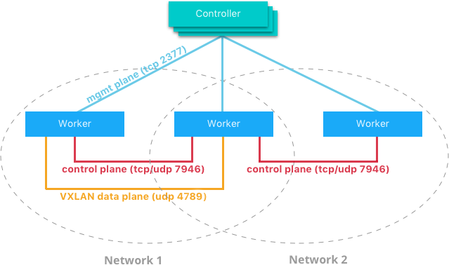
The network control plane is composed of several components that work together to achieve fast convergence across large scale networks. The distributed nature of the control plane ensures that cluster controller failures don’t affect network performance.
The Docker network control plane components are as follows:
- Message Dissemination updates nodes in a peer-to-peer fashion fanning out the information in each exchange to a larger group of nodes. Fixed intervals and peer group size ensures that network usage is constant even as the size of the cluster scales. Exponential information propagation across peers ensures that convergence is fast and bounded across any cluster size.
- Failure Detection utilizes direct and indirect hello messages to rule out network congestion and specific paths from causing false positive node failures.
- Full State Syncs occur periodically to achieve consistency faster and resolve temporary network partitions.
- Topology Aware algorithms understand the relative latency between themselves and other peers. This is used to optimize the peer groups which makes convergence faster and more efficient.
- Control Plane Encryption protects against man-in-the-middle and other attacks that could compromise network security.
Note
The Docker Network Control Plane is a component of Swarm and requires a Swarm mode cluster to operate.
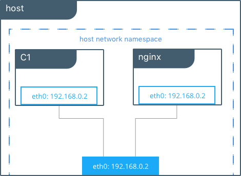
Docker Host Network Driver
The host network driver is most familiar to those new to Docker
because it’s the same networking configuration that Linux uses without
Docker. --net=host effectively turns Docker networking off and
containers use the host (or default) networking stack of the host
operating system.
Typically with other networking drivers, each container is placed in its
own network namespace (or sandbox) to provide complete network
isolation from each other. With the host driver containers are all
in the same host network namespace and use the network interfaces and IP
stack of the host. All containers in the host network are able to
communicate with each other on the host interfaces. From a networking
standpoint this is equivalent to multiple processes running on a host
without containers. Because they are using the same host interfaces, no
two containers are able to bind to the same TCP port. This may cause
port contention if multiple containers are being scheduled on the same
host.
# Create containers attached to the host network interface
host $ docker run --rm -itd --net host --name C1 alpine sh

host $ docker run --rm -itd --net host --name nginx nginx

# Show eth0 on the host
host $ ip -o -4 address show dev eth0 |cut -d’ ‘ -f1-7
2: eth0    inet 172.31.21.213/20

# Start a shell in the container C1 and show eth0 from C1
host $ docker exec -it C1 sh

C1 $ ip -o -4 address show dev eth0 | cut -d' ' -f1-7
2: eth0    inet 172.31.21.213/20

# Contact the nginx container through localhost on C1
C1 $ curl localhost
!DOCTYPE html>
<html>
<head>
<title>Welcome to nginx!</title>
...
In this example, the host (host), the container (C1), and nginx all
share the same interface for eth0 when containers use the host network.
This makes host ill-suited for multi-tenant or highly secure
applications. host containers have network access to every other
container on the host. Communication is possible between containers
using localhost as shown in the example when curl localhost is
executed from C1.
With the host driver, Docker does not manage any portion of the
container networking stack such as port mapping or routing rules. This
means that common networking flags like -p and --icc have no
meaning for the host driver. They are ignored. This does make the
host networking the simplest and lowest latency of the networking
drivers. The traffic path goes directly from the container process to
the host interface, offering bare-metal performance that is equivalent
to a non-containerized process.
Full host access and no automated policy management may make the
host driver a difficult fit as a general network driver. However,
host does have some interesting properties that may be applicable
for use cases such as ultra high performance applications or application
troubleshooting.
The host networking driver only works on Linux hosts, and is not supported on Docker Desktop, Docker Desktop Enterprise, or Mirantis Container Runtime on Windows Server.
Docker Bridge Network Driver
This section explains the default Docker bridge network as well as user-defined bridge networks.
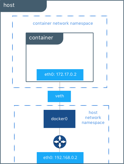
Default Docker Bridge Network
On any Linux host running Mirantis Container Runtime, there is, by default, a
local Docker network named bridge. This network is created using a
bridge network driver which instantiates a Linux bridge called docker0.
This may sound confusing.
bridgeis the name of the Docker networkbridgeis the Docker network driver, or template, from which this network is createddocker0is the name of the Linux bridge that is the kernel building block used to implement this network
On a standalone Linux Docker host, bridge is the default network that
containers connect to if no other network is specified(the analog on Windows is
the nat network type). In the following example a container is created with no
network parameters. Mirantis Container Runtime connects it to the bridge
network by default. Inside the container, notice eth0 which is created by
the bridge driver and given an address by the Docker native IPAM driver.
# Create a busybox container named "C1" and show its IP addresses
host $ docker run --rm -it --name C1 busybox sh
C1 $ ip address
4: eth0@if5: <BROADCAST,MULTICAST,UP,LOWER_UP,M-DOWN> mtu 1500 qdisc noqueue
    link/ether 02:42:ac:11:00:02 brd ff:ff:ff:ff:ff:ff
    inet 172.17.0.2/16 scope global eth0
...
Note
A container interface’s MAC address is dynamically generated and
embeds the IP address to avoid collision. Here ac:11:00:02
corresponds to 172.17.0.2.
The tool brctl on the host shows the Linux bridges that exist in the
host network namespace. It shows a single bridge called docker0.
docker0 has one interface, vetha3788c4, which provides
connectivity from the bridge to the eth0 interface inside container
C1.
host $ brctl show
bridge name      bridge id            STP enabled    interfaces
docker0          8000.0242504b5200    no             vethb64e8b8
Inside container C1, the container routing table directs traffic to
eth0 of the container and thus the docker0 bridge.
C1 $ ip route
default via 172.17.0.1 dev eth0
172.17.0.0/16 dev eth0  src 172.17.0.2
A container can have zero to many interfaces depending on how many networks it is connected to. Each Docker network can only have a single interface per container.
As shown in the host routing table, the IP interfaces in the global
network namespace now include docker0. The host routing table
provides connectivity between docker0 and eth0 on the external
network, completing the path from inside the container to the external
network.
host $ ip route
default via 172.31.16.1 dev eth0
172.17.0.0/16 dev docker0  proto kernel  scope link  src 172.17.42.1
172.31.16.0/20 dev eth0  proto kernel  scope link  src 172.31.16.102
By default bridge is assigned one subnet from the ranges
172.[17-31].0.0/16 or 192.168.[0-256].0/20 which does not overlap with
any existing host interface. The default bridge network can also be
configured to use user-supplied address
ranges.
Also, an existing Linux bridge can be used for the bridge network
rather than Docker creating one. Go to the Mirantis Container Runtime
docs
for more information about customizing bridge.
Note
The default bridge network is the only network that supports
legacy
links.
Name-based service discovery and user-provided IP addresses are
not supported by the default bridge network.
User-Defined Bridge Networks
In addition to the default networks, users can create their own networks
called user-defined networks of any network driver type. In the case
of user-defined bridge networks, a new Linux bridge is setup on the
host. Unlike the default bridge network, user-defined networks
supports manual IP address and subnet assignment. If an assignment isn’t
given, then Docker’s default IPAM driver assigns the next subnet
available in the private IP space.
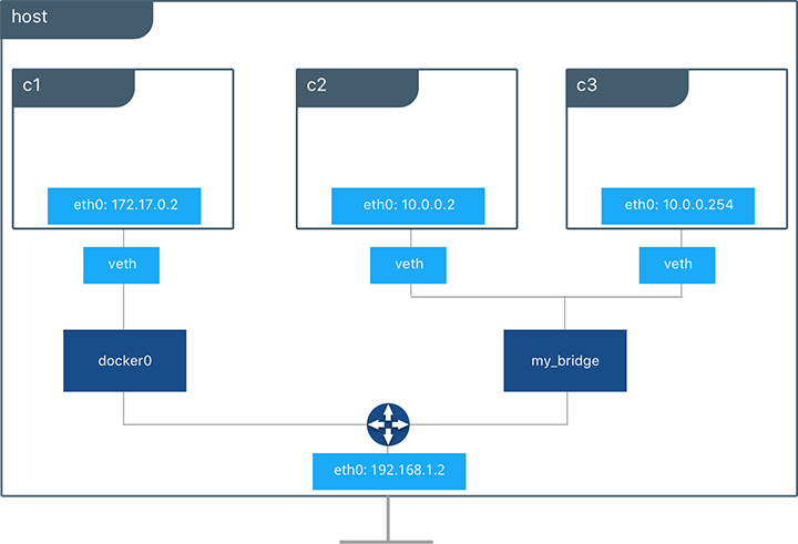
Below a user-defined bridge network is created with two containers
attached to it. A subnet is specified, and the network is named
my_bridge. One container is not given IP parameters, so the IPAM
driver assigns it the next available IP in the subnet. The other
container has its IP specified.
$ docker network create -d bridge --subnet 10.0.0.0/24 my_bridge
$ docker run --rm -itd --name C2 --net my_bridge busybox sh
$ docker run --rm -itd --name C3 --net my_bridge --ip 10.0.0.254 busybox sh
brctl now shows a second Linux bridge on the host. The name of the
Linux bridge, br-4bcC22f5e5b9, matches the Network ID of the
my_bridge network. my_bridge also has two veth interfaces
connected to containers C2 and C3.
$ brctl show
bridge name      bridge id            STP enabled    interfaces
br-b5db4578d8c9  8000.02428d936bb1    no             vethc9b3282
                                                     vethf3ba8b5
docker0          8000.0242504b5200    no             vethb64e8b8

$ docker network ls
NETWORK ID          NAME                DRIVER              SCOPE
b5db4578d8c9        my_bridge           bridge              local
e1cac9da3116        bridge              bridge              local
...
Listing the global network namespace interfaces shows the Linux networking
circuitry that’s been instantiated by Mirantis Container Runtime. Each veth
and Linux bridge interface appears as a link between one of the Linux bridges
and the container network namespaces.
$ ip link

1: lo: <LOOPBACK,UP,LOWER_UP> mtu 65536
2: eth0: <BROADCAST,MULTICAST,UP,LOWER_UP> mtu 9001
3: docker0: <BROADCAST,MULTICAST,UP,LOWER_UP> mtu 1500
5: vethb64e8b8@if4: <BROADCAST,MULTICAST,UP,LOWER_UP> mtu 1500
6: br-b5db4578d8c9: <BROADCAST,MULTICAST,UP,LOWER_UP> mtu 1500
8: vethc9b3282@if7: <BROADCAST,MULTICAST,UP,LOWER_UP> mtu 1500
10: vethf3ba8b5@if9: <BROADCAST,MULTICAST,UP,LOWER_UP> mtu 1500
...
External Access for Standalone Containers
By default all containers on the same Docker network (multi-host swarm scope or local scope) have connectivity with each other on all ports. Communication between different Docker networks and container ingress traffic that originates from outside Docker is firewalled. This is a fundamental security aspect that protects container applications from the outside world and from each other. This is outlined in more detail in security.
For most types of Docker networks (bridge and overlay included)
external ingress access for applications must be explicitly granted.
This is done through internal port mapping. Docker publishes ports
exposed on host interfaces to internal container interfaces. The
following diagram depicts ingress (bottom arrow) and egress (top arrow)
traffic to container C2. Outbound (egress) container traffic is
allowed by default. Egress connections initiated by containers are
masqueraded/SNATed to an ephemeral port (typically in the range of
32768 to 60999). Return traffic on this connection is allowed, and thus
the container uses the best routable IP address of the host on the
ephemeral port.
Ingress access is provided through explicit port publishing. Port publishing is done by Mirantis Container Runtime and can be controlled through MKE or the Mirantis Container Runtime CLI. A specific or randomly chosen port can be configured to expose a service or container. The port can be set to listen on a specific (or all) host interfaces, and all traffic is mapped from this port to a port and interface inside the container.
$ docker run -d --name C2 --net my_bridge -p 5000:80 nginx
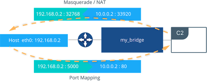
External access is configured using --publish / -p in the Docker
CLI or MKE. After running the above command, the diagram shows that
container C2 is connected to the my_bridge network and has an IP
address of 10.0.0.2. The container exposes its service to the
outside world on port 5000 of the host interface 192.168.0.2.
All traffic going to this interface:port is port published to
10.0.0.2:80 of the container interface.
Outbound traffic initiated by the container is masqueraded so that it is
sourced from ephemeral port 32768 on the host interface
192.168.0.2. Return traffic uses the same IP address and port for
its destination and is masqueraded internally back to the container
address:port 10.0.0.2:33920. When using port publishing, external
traffic on the network always uses the host IP and exposed port and
never the container IP and internal port.
For information about exposing containers and services in a cluster of Mirantis Container Runtimes read External Access for Swarm Services.
Overlay Driver Network Architecture
The native Docker overlay network driver radically simplifies many
of the challenges in multi-host networking. With the overlay driver,
multi-host networks are first-class citizens inside Docker without
external provisioning or components. overlay uses the
Swarm-distributed control plane to provide centralized management,
stability, and security across very large scale clusters. Overlay
networks function across Linux and Windows hosts.
VXLAN Data Plane
The overlay driver utilizes an industry-standard VXLAN data plane
that decouples the container network from the underlying physical
network (the underlay). The Docker overlay network encapsulates
container traffic in a VXLAN header which allows the traffic to traverse
the physical Layer 2 or Layer 3 network. The overlay makes network
segmentation dynamic and easy to control no matter what the underlying
physical topology. Use of the standard IETF VXLAN header promotes
standard tooling to inspect and analyze network traffic.
VXLAN has been a part of the Linux kernel since version 3.7, and Docker uses the native VXLAN features of the kernel to create overlay networks. The Docker overlay datapath is entirely in kernel space. This results in fewer context switches, less CPU overhead, and a low-latency, direct traffic path between applications and the physical NIC.
IETF VXLAN (RFC 7348) is a data-layer encapsulation format that overlays Layer 2 segments over Layer 3 networks. VXLAN is designed to be used in standard IP networks and can support large-scale, multi-tenant designs on shared physical network infrastructure. Existing on-premises and cloud-based networks can support VXLAN transparently.
VXLAN is defined as a MAC-in-UDP encapsulation that places container Layer 2 frames inside an underlay IP/UDP header. The underlay IP/UDP header provides the transport between hosts on the underlay network. The overlay is the stateless VXLAN tunnel that exists as point-to-multipoint connections between each host participating in a given overlay network. Because the overlay is independent of the underlay topology, applications become more portable. Thus, network policy and connectivity can be transported with the application whether it is on-premises, on a developer desktop, or in a public cloud.
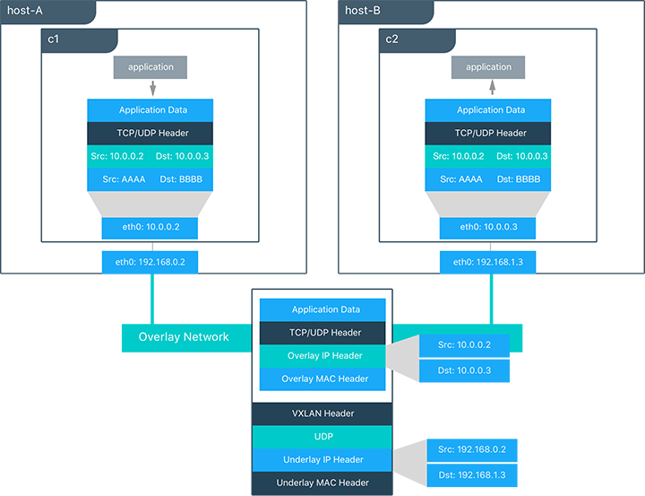
In this diagram, the packet flow on an overlay network is shown. Here
are the steps that take place when C1 sends C2 packets across
their shared overlay network:
C1does a DNS lookup forC2. Since both containers are on the same overlay network the Mirantis Container Runtime local DNS server resolvesC2to its overlay IP address10.0.0.3.- An overlay network is a L2 segment so
C1generates an L2 frame destined for the MAC address ofC2. - If this is the first time C1 has contacted C2, C1 issues an ARP request for C2, which is answered by the local operating system using an entry statically programmed by the local Mirantis Container Runtime.
- The frame is encapsulated with a VXLAN header by the
overlaynetwork driver. The distributed overlay control plane manages the locations and state of each VXLAN tunnel endpoint so it knows thatC2resides onhost-Bat the physical address of192.168.0.3. That address becomes the destination address of the underlay IP header. - Once encapsulated the packet is sent. The physical network is responsible of routing or bridging the VXLAN packet to the correct host.
- The packet arrives at the
eth0interface ofhost-Band is decapsulated by theoverlaynetwork driver. The original L2 frame fromC1is passed toC2’seth0interface and up to the listening application.
Overlay Driver Internal Architecture
The Docker Swarm control plane automates all of the provisioning for an
overlay network. No VXLAN configuration or operating system networking
configuration is required. Data-plane encryption, an optional feature of
overlays on Linux, is also automatically configured by the overlay
driver as networks are created. The user or network operator only has to
define the network (docker network create -d overlay ...) and attach
containers to that network.
During overlay network creation, Mirantis Container Runtime creates the network infrastructure required for overlays on each host. A Linux bridge is created per overlay along with its associated VXLAN interfaces. The Mirantis Container Runtime intelligently instantiates overlay networks on hosts only when a container attached to that network is scheduled on the host. This prevents sprawl of overlay networks where connected containers do not exist.
The following example creates an overlay network and attaches a container to that network. The Docker Swarm/MKE automatically creates the overlay network. The following example requires Swarm or MKE to be set up beforehand.
# Create an overlay named "ovnet" with the overlay driver
$ docker network create -d overlay --subnet 10.1.0.0/24 ovnet

# Create a service from running nginx and connect it to the "ovnet" network
$ docker service create --network ovnet nginx
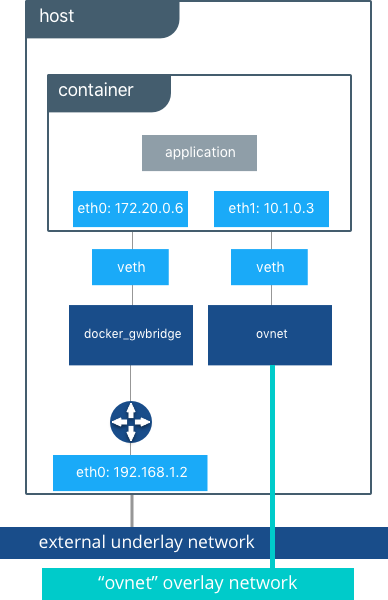
When the overlay network is created, notice that several interfaces and bridges are created inside the host as well as two interfaces inside this container.
# Peek into the container of this service to see its internal interfaces
$ ip address

# docker_gwbridge network
52: eth0@if55: <BROADCAST,MULTICAST,UP,LOWER_UP> mtu 1500
    link/ether 02:42:ac:14:00:06 brd ff:ff:ff:ff:ff:ff
    inet 172.20.0.6/16 scope global eth1
       valid_lft forever preferred_lft forever
    inet6 fe80::42:acff:fe14:6/64 scope link
       valid_lft forever preferred_lft forever

# overlay network interface
54: eth1@if53: <BROADCAST,MULTICAST,UP,LOWER_UP> mtu 1450
    link/ether 02:42:0a:01:00:03 brd ff:ff:ff:ff:ff:ff
    inet 10.1.0.3/24 scope global eth0
       valid_lft forever preferred_lft forever
    inet 10.1.0.2/32 scope global eth0
       valid_lft forever preferred_lft forever
    inet6 fe80::42:aff:fe01:3/64 scope link
       valid_lft forever preferred_lft forever
Two interfaces have been created inside the container that correspond to
two bridges that now exist on the host. On overlay networks, each
container has at least two interfaces that connect it to the overlay
and the docker_gwbridge respectively.
| Bridge | Purpose |
|---|---|
| overlay | The connection point to the overlay network that VXLAN encapsulates and (optionally) encrypts traffic between containers on the same overlay network. It extends the overlay across all hosts participating in this particular overlay. One existed per overlay subnet on a host, and it has the same name that a particular overlay network is given. |
| docker_gwbridge | The egress bridge for traffic leaving the cluster. Only one
docker_gwbridge exists per host. Container-to-Container traffic is
blocked on this bridge allowing only ingress/egress traffic. |
External Access for Docker Services
Swarm & MKE provide access to services from outside the cluster port
publishing. Ingress and egress for services do not depend on centralized
gateways, but distributed ingres/egress on the host where the specific
service task is running. There are two modes of port publishing for
services, host mode and ingress mode.
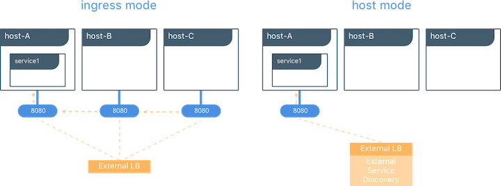
Ingress Mode Service Publishing
ingress mode port publishing utilizes the Swarm Routing
Mesh
to apply load balancing across the tasks in a service. Ingress mode
publishes the exposed port on every MKE/Swarm node. Ingress traffic to
the published port is load balanced by the Routing Mesh and directed via
round robin load balancing to one of the healthy tasks of the service.
Even if a given host is not running a service task, the port is
published on the host and is load balanced to a host that has a task.
When Swarm signals a task to stop, its loadbalancer entry is quiesced so
that it stops receiving new traffic.
$ docker service create --replicas 2 --publish mode=ingress,target=80,published=8080 nginx
Note
mode=ingress is the default mode for services. This command can
also be written with the shorthand version -p 80:8080. Port
8080 is exposed on every host on the cluster and load balanced
to the two containers in this service.
Host Mode Service Publishing
host mode port publishing exposes ports only on the host where
specific service tasks are running. The port is mapped directly to the
container on that host. To prevent port collision only a single task of
a given service can run on each host.
$ docker service create --replicas 2 --publish mode=host,target=80,published=8080 nginx
Note
host mode requires the mode=host flag. It publishes port
8080 locally on the hosts where these two containers are
running. It does not apply load balancing, so traffic to those nodes
are directed only to the local container. This can cause port
collision if there are not enough hosts with the published port
available for the number of replicas.
Ingress Design
There are many good use-cases for either publishing mode. ingress
mode works well for services that have multiple replicas and require
load balancing between those replicas. host mode works well if
external service discovery is already provided by another tool. Another
good use case for host mode is for global containers that exist one
per host. These containers may expose specific information about the
local host (such as monitoring or logging) that are only relevant for
that host and so you would not want to load balance when accessing that
service.
MACVLAN
The macvlan driver is a new implementation of the tried and true
network virtualization technique. The Linux implementations are
extremely lightweight because rather than using a Linux bridge for
isolation, they are simply associated with a Linux Ethernet interface or
sub-interface to enforce separation between networks and connectivity to
the physical network.
MACVLAN offers a number of unique features and capabilities. It has positive performance implications by virtue of having a very simple and lightweight architecture. Rather than port mapping, the MACVLAN driver provides direct access between containers and the physical network. It also allows containers to receive routable IP addresses that are on the subnet of the physical network.
MACVLAN use-cases may include:
- Very low-latency applications
- Network design that requires containers be on the same subnet as and using IPs as the external host network
The macvlan driver uses the concept of a parent interface. This
interface can be a physical interface such as eth0, a sub-interface
for 802.1q VLAN tagging like eth0.10 (.10 representing
VLAN 10), or even a bonded host adaptor which bundles two Ethernet
interfaces into a single logical interface.
A gateway address is required during MACVLAN network configuration. The gateway must be external to the host provided by the network infrastructure. MACVLAN networks allow access between containers on the same network. Access between different MACVLAN networks on the same host is not possible without routing outside the host.
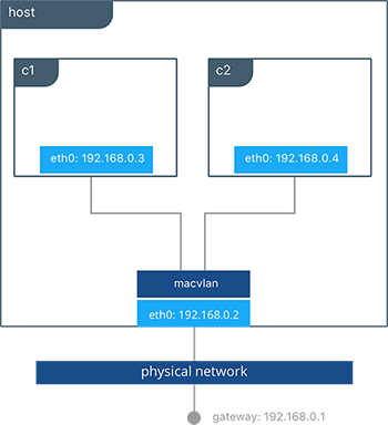
This example binds a MACVLAN network to eth0 on the host. It also
attaches two containers to the MACVLAN network and shows that they can
ping between themselves. Each container has an address on the
192.168.0.0/24 physical network subnet and its default gateway is an
interface in the physical network.
# Create of MACVLAN network "mvnet" bound to eth0 on the host
$ docker network create -d macvlan --subnet 192.168.0.0/24 --gateway 192.168.0.1 -o parent=eth0 mvnet

# Create two containers on the "mvnet" network
$ docker run --rm -itd --name C1 --net mvnet --ip 192.168.0.3 busybox sh
$ docker run --rm -it --name C2 --net mvnet --ip 192.168.0.4 busybox sh

$ ping 192.168.0.3
PING 127.0.0.1 (127.0.0.1): 56 data bytes
64 bytes from 127.0.0.1: icmp_seq=0 ttl=64 time=0.052 ms
As you can see in this diagram, C1 and C2 are attached via the
MACVLAN network called mvnet attached to eth0 on the host.
VLAN Trunking with MACVLAN
Trunking 802.1q to a Linux host is notoriously painful for many in
operations. It requires configuration file changes in order to be
persistent through a reboot. If a bridge is involved, a physical NIC
needs to be moved into the bridge, and the bridge then gets the IP
address. The macvlan driver completely manages sub-interfaces and
other components of the MACVLAN network through creation, destruction,
and host reboots.
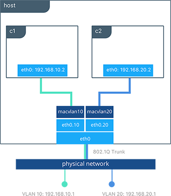
When the macvlan driver is instantiated with sub-interfaces it
allows VLAN trunking to the host and segments containers at L2. The
macvlan driver automatically creates the sub-interfaces and connects
them to the container interfaces. As a result each container is in a
different VLAN, and communication is not possible between them unless
traffic is routed in the physical network.
# Create a network called “macvlan10” in VLAN 10
$ docker network create -d macvlan --subnet 192.168.10.0/24 --gateway 192.168.10.1 \
    -o parent=eth0.10 macvlan10

# Create a network called "macvlan20" network in VLAN 20
$ docker network create -d macvlan --subnet 192.168.20.0/24 --gateway 192.168.20.1 \
    -o parent=eth0.20 macvlan20

# Create two containers on separate MACVLAN networks
$ docker run --rm -itd --name C1 --net macvlan10 --ip 192.168.10.2 busybox sh
$ docker run --rm -it --name C2 --net macvlan20 --ip 192.168.20.2 busybox sh
In the preceding configuration we’ve created two separate networks using
the macvlan driver that are configured to use a sub-interface as
their parent interface. The macvlan driver creates the
sub-interfaces and connects them between the host’s eth0 and the
container interfaces. The host interface and upstream switch must be set
to switchport mode trunk so that VLANs are tagged going across the
interface. One or more containers can be connected to a given MACVLAN
network to create complex network policies that are segmented via L2.
Because multiple MAC addresses are living behind a single host interface you might need to enable promiscuous mode on the interface depending on the NIC’s support for MAC filtering.
None (Isolated) Network Driver
Similar to the host network driver, the none network driver is
essentially an unmanaged networking option. Mirantis Container Runtime does not
create interfaces inside the container, establish port mapping, or
install routes for connectivity. A container using --net=none is
completely isolated from other containers and the host. If network
connectivity is required, the networking admin or external tools must be
used to provide this plumbing. A container using none only has a
loopback interface and no other interfaces.
Unlike the host driver, the none driver creates a separate
namespace for each container. This guarantees container network
isolation between any containers and the host.
Note
Containers using --net=none or --net=host cannot be
connected to any other Docker networks.
Physical Network Design Requirements
Docker Enterprise and Docker networking are designed to run over common data center network infrastructure and topologies. Its centralized controller and fault-tolerant cluster guarantee compatibility across a wide range of network environments. The components that provide networking functionality (network provisioning, MAC learning, overlay encryption) are either a part of MKE, Mirantis Container Runtime, or the host operating system itself. No extra components or special networking features are required to run any of the native Docker networking drivers.
More specifically, the Docker native network drivers have NO requirements for:
- Multicast
- External key-value stores
- Specific routing protocols
- Layer 2 adjacencies between hosts
- Specific topologies such as spine & leaf, traditional 3-tier, and PoD designs. Any of these topologies are supported.
This is in line with the Container Networking Model which promotes application portability across all environments while still achieving the performance and policy required of applications.
Swarm Native Service Discovery
Docker uses embedded DNS to provide service discovery for containers running on
a single Mirantis Container Runtime and tasks running in a Docker Swarm.
Mirantis Container Runtime has an internal DNS server that provides name
resolution to all of the containers on the host in user-defined bridge,
overlay, and MACVLAN networks. Each Docker container ( or task in Swarm
mode) has a DNS resolver that forwards DNS queries to Mirantis Container
Runtime, which acts as a DNS server. Mirantis Container Runtime then checks if
the DNS query belongs to a container or service on network(s) that the
requesting container belongs to. If it does, then Mirantis Container Runtime
looks up the IP address that matches a container, task, orservice’s
name in its key-value store and returns that IP or service Virtual IP
(VIP) back to the requester.
Service discovery is network-scoped, meaning only containers or tasks that are on the same network can use the embedded DNS functionality. Containers not on the same network cannot resolve each other’s addresses. Additionally, only the nodes that have containers or tasks on a particular network store that network’s DNS entries. This promotes security and performance.
If the destination container or service does not belong on the same
network(s) as the source container, then Mirantis Container Runtime forwards
the DNS query to the configured default DNS server.

In this example there is a service of two containers called
myservice. A second service (client) exists on the same network.
The client executes two curl operations for docker.com and
myservice. These are the resulting actions:
- DNS queries are initiated by
clientfordocker.comandmyservice. - The container’s built-in resolver intercepts the DNS queries on
127.0.0.11:53and sends them to Mirantis Container Runtime’s DNS server. myserviceresolves to the Virtual IP (VIP) of that service which is load balanced by the operating system network stack to the individual task IP addresses. Container names resolve as well, albeit directly to their IP addresses.docker.comdoes not exist as a service name in themynetnetwork and so the request is forwarded to the configured default DNS server.
Docker Native Load Balancing
Docker Swarm clusters have built-in internal and external load balancing capabilities are built right in to the engine that leverage the operating system networking stack. Internal load balancing provides for load balancing between containers within the same Swarm or MKE cluster. External load balancing provides for the load balancing of ingress traffic entering a cluster.
MKE Internal Load Balancing
Internal load balancing is instantiated automatically when Docker services are created. When services are created in a Docker Swarm cluster, they are automatically assigned a Virtual IP (VIP) that is part of the service’s network. The VIP is returned when resolving the service’s name. Traffic to that VIP is automatically sent to all healthy tasks of that service across the overlay network. This approach avoids any application-level load balancing because only a single IP is returned to the client. Docker takes care of routing and equally distributing the traffic across the healthy service tasks.

To see the VIP, run a docker service inspect my_service as follows:
# Create an overlay network called mynet
$ docker network create -d overlay mynet
a59umzkdj2r0ua7x8jxd84dhr

# Create myservice with 2 replicas as part of that network
$ docker service create --network mynet --name myservice --replicas 2 busybox ping localhost
8t5r8cr0f0h6k2C3k7ih4l6f5

# See the VIP that was created for that service
$ docker service inspect myservice
...

"VirtualIPs": [
                {
                    "NetworkID": "a59umzkdj2r0ua7x8jxd84dhr",
                    "Addr": "10.0.0.3/24"
                },
]
Note
DNS round robin (DNS RR) load balancing is another load balancing
option for services (configured with --endpoint-mode dnsrr). In
DNS RR mode a VIP is not created for each service. The Docker DNS
server resolves a service name to individual container IPs in round
robin fashion.
Swarm External L4 Load Balancing (Docker Routing Mesh)
You can expose services externally by using the --publish flag when
creating or updating the service. Publishing ports in Docker Swarm mode
means that every node in your cluster is listening on that port. But
what happens if the service’s task isn’t on the node that is listening
on that port?
This is where routing mesh comes into play. Routing mesh leverages
operating system primitives (IPVS+iptables on Linux and VFP on Windows)
to create a powerful cluster-wide transport-layer (L4) load balancer. It
allows the Swarm nodes to accept connections on the services’ published
ports. When any Swarm node receives traffic destined to the published
TCP/UDP port of a running service, it forwards it to service’s VIP
using a pre-defined overlay network called ingress. The ingress
network behaves similarly to other overlay networks but its sole purpose
is to provide inter-host transport for mesh routing traffic from
external clients to cluster services. It uses the same VIP-based
internal load balancing as described in the previous section.
Once you launch services, you can create an external DNS record for your applications and map it to any or all Docker Swarm nodes. You do not need to know where the container is running as all nodes in your cluster look as one with the routing mesh routing feature.
# Create a service with two replicas and publish port 8000 on the cluster
$ docker service create --name app --replicas 2 --network appnet -p 8000:80 nginx
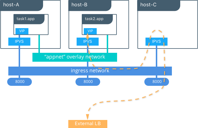
This diagram illustrates how the routing mesh works.
- A service is created with two replicas, and it is port mapped
externally to port
8000. - The routing mesh exposes port
8000on each host in the cluster. - Traffic destined for the
appcan enter on any host. In this case the external LB sends the traffic to a host without a service replica. - The kernel’s IPVS load balancer redirects traffic on the
ingressoverlay network to a healthy service replica.
MKE External L7 Load Balancing (HTTP Routing Mesh)
MKE provides built-in L7 HTTP/HTTPS load balancing. URLs can be load balanced to services and load balanced across the service replicas.

See also
Check out the ucp-ingress-swarm reference architecture to learn more about the MKE layer 7 load balanceing design.
Docker Network Security and Encryption
Network security is a top-of-mind consideration when designing and implementing containerized workloads with Docker. In this section, key security considerations when deploying Docker networks are covered.
Network Segmentation and Data Plane Security
Docker manages distributed firewall rules to segment Docker networks and prevent malicious access to container resources. By default, Docker networks are segmented from each other to prevent traffic between them. This approach provides true network isolation at Layer 3.
The Docker engine manages host firewall rules that prevent access between networks and manages ports for exposed containers. In a Swarm & MKE clusters this creates a distributed firewall that dynamically protects applications as they are scheduled in the cluster.
This table outlines some of the access policies with Docker networks.
| Path | Access |
|---|---|
| Within a Docker Network | Access is permitted between all containers on all ports on the same Docker network. This applies for all network types - swarm scope, local scope, built-in, and remote drivers. |
| Between Docker Networks | Access is denied between Docker networks by distributed host firewall rules that are managed by the Docker engine. Containers can be attached to multiple networks to communicate between different Docker networks. Network connectivity between Docker networks can also be managed external to the host via API. |
| Egress from a Docker Network | Traffic originating from inside a Docker network destined for outside a Docker host is permitted. The host’s local, stateful firewall tracks connections to permit responses for that connection. |
| Ingress to a Docker Network | Ingress traffic is denied by default. Port exposure through host ports or ingress mode ports provides explicit ingress access. An exception to this is the MACVLAN driver which operates in the same IP space as the external network and is fully open within that network. Other remote drivers that operate similarly to MACVLAN may also allow ingress traffic. |
Control Plane Security
Docker Swarm comes with integrated PKI. All managers and nodes in the Swarm have a cryptographically signed identity in the form of a signed certificate. All manager-to-manager and manager-to-node control communication is secured out of the box with TLS. There is no need to generate certs externally or set up any CAs manually to get end-to-end control plane traffic secured in Docker Swarm mode. Certificates are periodically and automatically rotated.
Data Plane Network Encryption
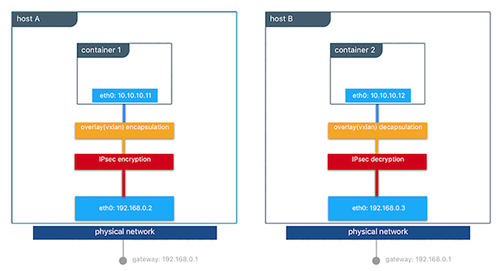
Docker supports IPSec encryption for overlay networks between Linux hosts out-of-the-box. The Swarm & MKE managed IPSec tunnels encrypt network traffic as it leaves the source container and decrypts it as it enters the destination container. This ensures that your application traffic is highly secure when it’s in transit regardless of the underlying networks. In a hybrid, multi-tenant, or multi-cloud environment, it is crucial to ensure data is secure as it traverses networks you might not have control over.
This diagram illustrates how to secure communication between two containers running on different hosts in a Docker Swarm.
This feature works can be enabled per network at the time of creation by
adding the --opt encrypted=true option (e.g
docker network create -d overlay --opt encrypted=true <NETWORK_NAME>).
After the network gets created, you can launch services on that network
(e.g
docker service create --network <NETWORK_NAME> <IMAGE> <COMMAND>).
When two tasks of the same network are created on two different hosts,
an IPsec tunnel is created between them and traffic gets encrypted as it
leaves the source host and decrypted as it enters the destination host.
The Swarm leader periodically regenerates a symmetrical key and distributes it securely to all cluster nodes. This key is used by IPsec to encrypt and decrypt data plane traffic. The encryption is implemented via IPSec in host-to-host transport mode using AES-GCM.
Management Plane Security & RBAC with MKE
When creating networks with MKE, teams and labels define access to container resources. Resource permission labels define who can view, configure, and use certain Docker networks.

This MKE screenshot shows the use of the label production-team to
control access to this network to only members of that team.
Additionally, options like network encryption and others can be toggled
via MKE.
IP Address Management
The Container Networking Model (CNM) provides flexibility in how IP addresses are managed. There are two methods for IP address management.
- CNM has a native IPAM driver that does simple allocation of IP addresses globally for a cluster and prevents overlapping allocations. The native IPAM driver is what is used by default if no other driver is specified.
- CNM has interfaces to use remote IPAM drivers from other vendors and the community. These drivers can provide integration into existing vendor or self-built IPAM tools.
Manual configuration of container IP addresses and network subnets can be done using MKE, the CLI, or Docker APIs. The address request goes through the chosen driver which then decides how to process the request.
Subnet size and design is largely dependent on a given application and the specific network driver. IP address space design is covered in more depth for each Network Deployment Model in the next section. The uses of port mapping, overlays, and MACVLAN all have implications on how IP addressing is arranged. In general, container addressing falls into two buckets. Internal container networks (bridge and overlay) address containers with IP addresses that are not routable on the physical network by default. You can find more information about customizing the behavior of the Internal IPAM in the MKE Installation Documentation. MACVLAN networks provide IP addresses to containers that are on the subnet of the physical network. Thus, traffic from container interfaces can be routable on the physical network. It is important to note that subnets for internal networks (bridge, overlay) should not conflict with the IP space of the physical underlay network. Overlapping address space can cause traffic to not reach its destination.
Network Troubleshooting
Docker network troubleshooting can be difficult for devops and network
engineers. With proper understanding of how Docker networking works and
the right set of tools, you can troubleshoot and resolve these network
issues. One recommended way is to use the
netshoot container to
troubleshoot network problems. The netshoot container has a set of
powerful networking troubleshooting tools that can be used to
troubleshoot Docker network issues.
The power of using a troubleshooting container like netshoot is that the
network troubleshooting tools are portable. The netshoot container
can be attached to any network, can be placed in the host network
namespace, or in another container’s network namespace to inspect any
viewpoint of the host network.
It containers the following tools and more:
- iperf
- tcpdump
- netstat
- iftop
- drill
- util-linux (nsenter)
- curl
- nmap
Network Deployment Models
The following example uses a fictional app called `Docker Pets <https://github.com/mark-church/docker-pets>`__ to illustrate the Network Deployment Models. It serves up images of pets on a web page while counting the number of hits to the page in a backend database.
webis a front-end web server based on thechrch/docker-pets:1.0imagedbis aconsulbackend
chrch/docker-pets expects an environment variable DB that tells
it how to find the backend db service.
Bridge Driver on a Single Host
This model is the default behavior of the native Docker bridge
network driver. The bridge driver creates a private network internal
to the host and provides an external port mapping on a host interface
for external connectivity.
$ docker network create -d bridge petsBridge

$ docker run -d --net petsBridge --name db consul

$ docker run -it --env "DB=db" --net petsBridge --name web -p 8000:5000 chrch/docker-pets:1.0
Starting web container e750c649a6b5
 * Running on http://0.0.0.0:5000/ (Press CTRL+C to quit)
Note
When an IP address is not specified, port mapping is exposed on all
interfaces of a host. In this case the container’s application is
exposed on 0.0.0.0:8000. To provide a specific IP address to
advertise on use the flag -p IP:host_port:container_port. More
options to expose ports can be found in the Docker
docs.
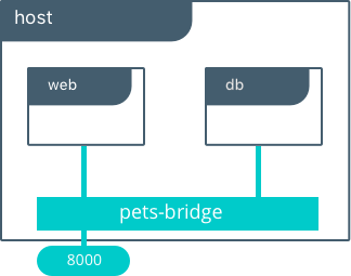
The application is exposed locally on this host on port 8000 on all
of its interfaces. Also supplied is DB=db, providing the name of the
backend container. The Mirantis Container Runtime’s built-in DNS resolves this
container name to the IP address of db. Since bridge is a local
driver, the scope of DNS resolution is only on a single host.
The output below shows us that our containers have been assigned private
IPs from the 172.19.0.0/24 IP space of the petsBridge network.
Docker uses the built-in IPAM driver to provide an IP from the
appropriate subnet if no other IPAM driver is specified.
$ docker inspect --format {{.NetworkSettings.Networks.petsBridge.IPAddress}} web
172.19.0.3

$ docker inspect --format {{.NetworkSettings.Networks.petsBridge.IPAddress}} db
172.19.0.2
These IP addresses are used internally for communication internal to the
petsBridge network. These IPs are never exposed outside of the host.
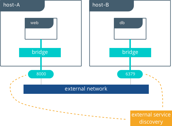
Multi-Host Bridge Driver with External Service Discovery
Because the bridge driver is a local scope driver, multi-host
networking requires a multi-host service discovery (SD) solution.
External SD registers the location and status of a container or service
and then allows other services to discover that location. Because the
bridge driver exposes ports for external access, external SD stores the
host-ip:port as the location of a given container.
In the following example, the location of each service is manually
configured, simulating external service discovery. The location of the
db service is passed to web via the DB environment variable.
# Create the backend db service and expose it on port 8500
host-A $ docker run -d -p 8500:8500 --name db consul

# Display the host IP of host-A
host-A $ ip add show eth0 | grep inet
    inet 172.31.21.237/20 brd 172.31.31.255 scope global eth0
    inet6 fe80::4db:c8ff:fea0:b129/64 scope link

# Create the frontend web service and expose it on port 8000 of host-B
host-B $ docker run -d -p 8000:5000 -e 'DB=172.31.21.237:8500' --name web chrch/docker-pets:1.0
The web service should now be serving its web page on port 8000
of host-B IP address.
Note
In this example we don’t specify a network to use, so the default
Docker bridge network is selected automatically.
When we configure the location of db at 172.31.21.237:8500, we are
creating a form of service discovery. We are statically configuring the
location of the db service for the web service. In the single host
example, this was done automatically because Mirantis Container Runtime
provided built-in DNS resolution for the container names. In this multi-host
example we are doing the service discovery manually.
The hardcoding of application location is not recommended for production. External service discovery tools exist that provide these mappings dynamically as containers are created and destroyed in a cluster. Some examples are Consul and etcd.
The next section examines the overlay driver scenario, which
provides global service discovery across a cluster as a built-in
feature. This simplicity is a major advantage of the overlay driver,
as opposed to using multiple external tools to provide network services.
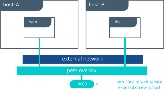
Multi-Host with Overlay Driver
This model utilizes the native overlay driver to provide multi-host
connectivity out of the box. The default settings of the overlay driver
provide external connectivity to the outside world as well as internal
connectivity and service discovery within a container application. The
Overlay Driver Architecture
section reviews the internals of the Overlay driver which you should
review before reading this section.
This example re-uses the previous docker-pets application. Set up a
Docker Swarm prior to following this example. For instructions on how to
set up a Swarm read the Docker
docs.
After the Swarm is set up, use the docker service create command to
create containers and networks to be managed by the Swarm.
The following shows how to inspect your Swarm, create an overlay network, and then provision some services on that overlay network. All of these commands are run on a MKE/swarm controller node.
# Display the nodes participating in this swarm cluster that was already created
$ docker node ls
ID                           HOSTNAME          STATUS  AVAILABILITY  MANAGER STATUS
a8dwuh6gy5898z3yeuvxaetjo    host-B  Ready   Active
elgt0bfuikjrntv3C33hr0752 *  host-A  Ready   Active        Leader

# Create the dognet overlay network
host-A $ docker network create -d overlay petsOverlay

# Create the backend service and place it on the dognet network
host-A $ docker service create --network petsOverlay --name db consul

# Create the frontend service and expose it on port 8000 externally
host-A $ docker service create --network petsOverlay -p 8000:5000 -e 'DB=db' \
           --name web chrch/docker-pets:1.0

host-A $ docker service ls
ID            NAME  MODE        REPLICAS  IMAGE
lxnjfo2dnjxq  db    replicated  1/1       consul:latest
t222cnez6n7h  web   replicated  1/1       chrch/docker-pets:1.0
As in the single-host bridge example, we pass in DB=db as an
environment variable to the web service. The overlay driver resolves
the service name db to the db service VIP overlay IP address.
Communication between web and db occurs exclusively using the
overlay IP subnet.
Note
Inside overlay and bridge networks, all TCP and UDP ports to containers are open and accessible to all other containers attached to the overlay network.
The web service is exposed on port 8000, and the routing
mesh exposes port 8000 on every host in the Swarm cluster. Test if
the application is working by going to <host-A>:8000 or
<host-B>:8000 a the browser.
Overlay Benefits and Use Cases
- Very simple multi-host connectivity for small and large deployments
- Provides service discovery and load balancing with no extra configuration or components
- Useful for east-west micro-segmentation via encrypted overlays
- Routing mesh can be used to advertise a service across an entire cluster
Tutorial App: MACVLAN Bridge Mode
There may be cases where the application or network environment requires containers to have routable IP addresses that are a part of the underlay subnets. The MACVLAN driver provides an implementation that makes this possible. As described in the MACVLAN Architecture section, a MACVLAN network binds itself to a host interface. This can be a physical interface, a logical sub-interface, or a bonded logical interface. It acts as a virtual switch and provides communication between containers on the same MACVLAN network. Each container receives a unique MAC address and an IP address of the physical network that the node is attached to.
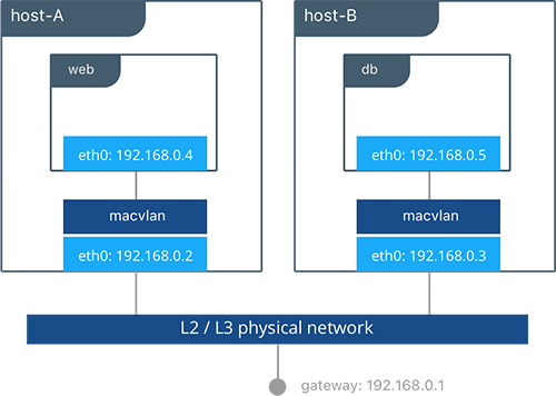
In this example, the Pets application is deployed on to host-A and
host-B.
# Creation of local macvlan network on both hosts
host-A $ docker network create -d macvlan --subnet 192.168.0.0/24 --gateway 192.168.0.1 \
           -o parent=eth0 petsMacvlan
host-B $ docker network create -d macvlan --subnet 192.168.0.0/24 --gateway 192.168.0.1 \
           -o parent=eth0 petsMacvlan

# Creation of db container on host-B
host-B $ docker run -d --net petsMacvlan --ip 192.168.0.5 --name db consul

# Creation of web container on host-A
host-A $ docker run -it --net petsMacvlan --ip 192.168.0.4 -e 'DB=192.168.0.5:8500' \
           --name web chrch/docker-pets:1.0
This may look very similar to the multi-host bridge example but there are a couple notable differences:
- The reference from
webtodbuses the IP address ofdbitself as opposed to the host IP. Remember that withmacvlancontainer IPs are routable on the underlay network. - We do not expose any ports for
dborwebbecause any ports opened in the container are immediately be reachable using the container IP address.
While the macvlan driver offers these unique advantages, one area
that it sacrifices is portability. MACVLAN configuration and deployment
is heavily tied to the underlay network. Container addressing must
adhere to the physical location of container placement in addition to
preventing overlapping address assignment. Because of this, care must be
taken to manage IPAM externally to a MACVLAN network. Overlapping IP
addressing or incorrect subnets can lead to loss of container
connectivity.
The MACVLAN driver can also be used with swarm services through the use of config-only local networks. For more information see the UCP User Guide.
MACVLAN Benefits and Use Cases
- Very low latency applications can benefit from the
macvlandriver because it does not utilize NAT. - MACVLAN can provide an IP per container, which may be a requirement in some environments.
- More careful consideration for IPAM must be taken into account.
Conclusion
Docker is quickly evolving, and the networking options are growing to satisfy more and more use cases every day. Incumbent networking vendors, pure-play SDN vendors, and Docker itself are all contributors to this space.
This document detailed some but not all of the possible deployments and CNM network drivers that exist. While there are many individual drivers and even more ways to configure those drivers, we hope you can see that there are only a few common models routinely deployed. Understanding the tradeoffs with each model is key to long term success.