Docker Enterprise products v3.0 documentation
Warning
Mirantis stopped maintaining this documentation set as of 2021-07-21, in correlation with the End of Life date for MKE 3.2.x and MSR 2.7.x. The company continues to support MCR 19.03.x and its documentation.
For the latest MKE, MSR, and MCR product documentation, refer to:
Docker Enterprise
Warning
Mirantis stopped maintaining this documentation set as of 2021-07-21, in correlation with the End of Life date for MKE 3.2.x and MSR 2.7.x. The company continues to support MCR 19.03.x and its documentation.
For the latest MKE, MSR, and MCR product documentation, refer to:
Docker Enterprise
Docker Enterprise is a standards-based container platform for development and delivery of modern applications. Docker Enterprise is designed for application developers and IT teams who build, share, and run business-critical applications at scale in production. Docker Enterprise provides a consistent and secure end-to-end application pipeline, choice of tools and languages, and globally consistent Kubernetes environments that run in any cloud.
Docker Enterprise enables deploying highly available workloads using either the Docker Kubernetes Service or Docker Swarm. You can join thousands of physical or virtual machines together to create a cluster, allowing you to deploy your applications at scale and to manage your clusters from a centralized place.
Docker Enterprise automates many of the tasks that orchestration requires, like provisioning pods, containers, and cluster resources. Self-healing components ensure that Docker Enterprise clusters remain highly available.
Docker Kubernetes service
The Docker Kubernetes Service fully supports all Docker Enterprise features, including role-based access control, LDAP/AD integration, image scanning and signing enforcement policies, and security policies.
Docker Kubernetes Services features include:
- Kubernetes orchestration full feature set
- CNCF Certified Kubernetes conformance
- Kubernetes app deployment via MKE web UI or CLI (kubectl)
- Compose stack deployment for Swarm and Kubernetes apps (docker stack deploy)
- Role-based access control for Kubernetes workloads
- Ingress Controllers with Kubernetes L7 routing
- Pod Security Policies to define a set of conditions that a pod must run with in order to be accepted into the system
- Container Storage Interface (CSI) support
- iSCSI support for Kubernetes
- Kubernetes-native ingress (Istio)
In addition, MKE integrates with Kubernetes by using admission controllers, which enable:
- Authenticating user client bundle certificates when communicating directly with the Kubernetes API server
- Authorizing requests via the MKE role-based access control model
- Assigning nodes to a namespace by injecting a
NodeSelectorautomatically to workloads via admission control - Keeping all nodes in both Kubernetes and Swarm orchestrator inventories
- Fine-grained access control and privilege escalation prevention without
the
PodSecurityPolicyadmission controller - Resolving images of deployed workloads automatically, and accepting or rejecting images based on MKE’s signing-policy feature
The default Docker Enterprise installation includes both Kubernetes and Swarm components across the cluster, so every newly joined worker node is ready to schedule Kubernetes or Swarm workloads.
Kubernetes CLI
Docker Enterprise exposes the standard Kubernetes API, so you can use kubectl to manage your Kubernetes workloads:
kubectl cluster-info
Which produces output similar to the following:
Kubernetes master is running at https://54.200.115.43:6443
KubeDNS is running at https://54.200.115.43:6443/api/v1/namespaces/kube-system/services/kube-dns:dns/proxy

To further debug and diagnose cluster problems, use 'kubectl cluster-info
dump'.
Orchestration platform features
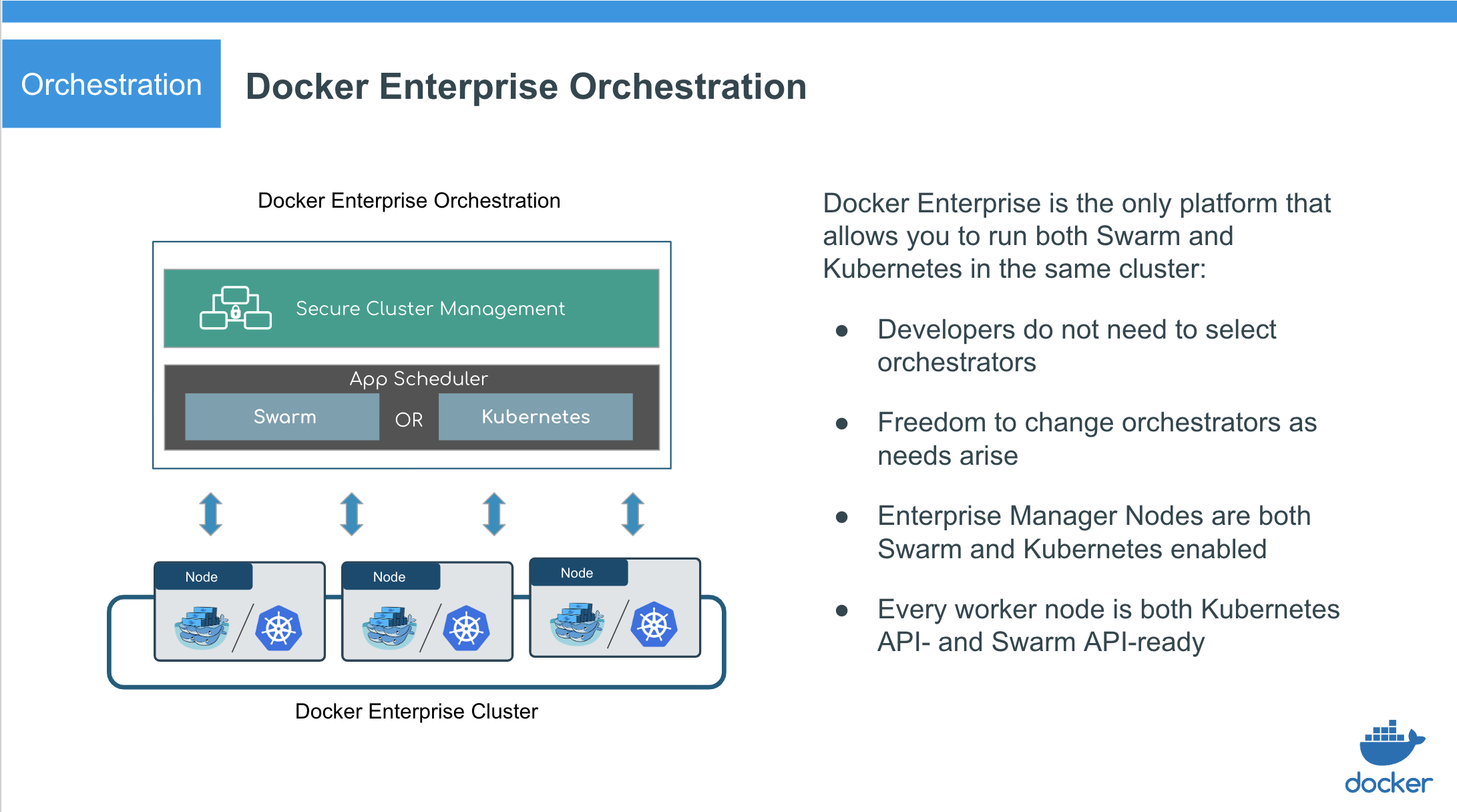
- Docker Enterprise manager nodes are both Swarm managers and Kubernetes masters, to enable high availability
- Allocate worker nodes for Swarm or Kubernetes workloads (or both)
- Single pane of glass for monitoring apps
- Enhanced Swarm hostname routing mesh with Interlock 2.0
- One platform-wide management plane: secure software supply chain, secure multi-tenancy, and secure and highly available node management
Security and access control
Docker Enterprise has its own built-in authentication mechanism with role-based access control (RBAC), so that you can control who can access and make changes to your cluster and applications. Also, Docker Enterprise authentication integrates with LDAP services and supports SAML SCIM to proactively synchronize with authentication providers. You can also opt to enable the PKI authenticati onto use client certificates, rather than username and password.
Docker Enterprise integrates with Mirantis Secure Registry so that you can keep the Docker images you use for your applications behind your firewall, where they are safe and can’t be tampered with. You can also enforce security policies and only allow running applications that use Docker images you know and trust.
Windows application security
Windows applications typically require Active Directory authentication in order to communicate with other services on the network. Container-based applications use Group Managed Service Accounts (gMSA) to provide this authentication. Docker Swarm fully supports the use of gMSAs with Windows containers.
Secure supply chain
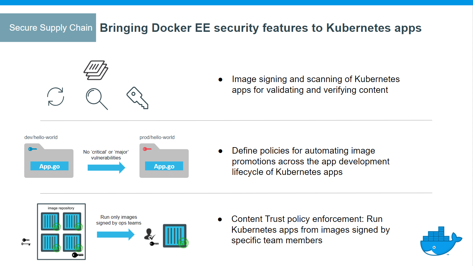
- MSR support for the Docker App format, based on the CNAB specification
- Image signing and scanning of Kubernetes and Swarm images and Docker Apps for validating and verifying content
- Image promotion with mirroring between registries as well as Docker Hub
- Define policies for automating image promotions across the app development lifecycle of Kubernetes and Swarm apps
Docker Enterprise CLI
Docker Enterprise exposes the standard Docker API, so you can continue using the tools that you already know, including the Docker CLI client, to deploy and manage your applications.
For example, you can use the docker info command to check the status of a Swarm managed by Docker Enterprise:
docker info
Which produces output similar to the following:
Containers: 38
Running: 23
Paused: 0
Stopped: 15
Images: 17
Server Version: 17.06
...
Swarm: active
NodeID: ocpv7el0uz8g9q7dmw8ay4yps
Is Manager: true
ClusterID: tylpv1kxjtgoik2jnrg8pvkg6
Managers: 1
...
Manage Docker Enterprise
Backup Docker Enterprise
This document provides instructions and best practices for Docker Enterprise backup procedures for all components of the platform.
To back up Docker Enterprise, you must create individual backups for each of the following components:
If you do not create backups for all components, you cannot restore your deployment to its previous state.
Test each backup you create. One way to test your backups is to do a fresh installation on a separate infrastructure with the backup. Refer to Restore Docker Enterprise for additional information.
Note: Application data backup is not included in this information. Persistent storage data backup is the responsibility of the storage provider for the storage plugin or driver.
Restore Docker Enterprise
You should only restore Docker Enterprise Edition from a backup as a last resort. If you’re running Docker Enterprise in high-availability mode, you can remove unhealthy nodes from the swarm and join new ones to bring the swarm to an healthy state.
To restore Docker Enterprise, restore components individually and in the following order:
Upgrade Docker Enterprise
To upgrade Docker Enterprise, you must individually upgrade each of the following components:
Because some components become temporarily unavailable during an upgrade, schedule upgrades to occur outside of peak business hours to minimize impact to your business.
Cluster upgrade best practices
Mirantis Container Runtime upgrades in Swarm clusters should follow these guidelines in order to avoid IP address space exhaustion and associated application downtime.
- New workloads should not be actively scheduled in the cluster during upgrades.
- Differences in the major (X.y.z.) or minor (x.Y.z) version numbers between the managers and workers can cause unintended consequences when new workloads are scheduled.
- Manager nodes should all be upgraded first before upgrading worker nodes. Upgrading manager nodes sequentially is recommended if live workloads are running in the cluster during the upgrade.
- Once manager nodes are upgraded worker nodes should be upgraded next and then the Swarm cluster upgrade is complete.
- If running MKE, the MKE upgrade should follow once all of the Swarm engines have been upgraded.
Create a backup
Before upgrading Mirantis Container Runtime, you should make sure you create a backup. This makes it possible to recover if anything goes wrong during the upgrade.
Check the compatibility matrix
You should also check the compatibility matrix, to make sure all Mirantis Container Runtime components are certified to work with one another. You may also want to check the Mirantis Container Runtime maintenance lifecycle, to understand until when your version may be supported.
Apply firewall rules
Before you upgrade, make sure:
Your firewall rules are configured to allow traffic in the ports MKE uses for communication. Learn about MKE port requirements.
Make sure you don’t have containers or services that are listening on ports used by MKE.
Configure your load balancer to forward TCP traffic to the Kubernetes API server port (6443/TCP by default) running on manager nodes.
Externally signed certificates are used by the Kubernetes API server and the MKE controller.
IP address consumption in 18.09+
In Swarm overlay networks, each task connected to a network consumes an
IP address on that network. Swarm networks have a finite amount of IPs
based on the --subnet configured when the network is created. If no
subnet is specified then Swarm defaults to a /24 network with 254
available IP addresses. When the IP space of a network is fully
consumed, Swarm tasks can no longer be scheduled on that network.
Starting with Mirantis Container Runtime 18.09 and later, each Swarm node will consume an IP address from every Swarm network. This IP address is consumed by the Swarm internal load balancer on the network. Swarm networks running on MCR versions 18.09 or greater must be configured to account for this increase in IP usage. Networks at or near consumption prior to engine version 18.09 may have a risk of reaching full utilization that will prevent tasks from being scheduled on to the network.
Maximum IP consumption per network at any given moment follows the following formula:
Max IP Consumed per Network = Number of Tasks on a Swarm Network + 1 IP for each node where these tasks are scheduled
To prevent this from happening, overlay networks should have enough capacity prior to an upgrade to 18.09, such that the network will have enough capacity after the upgrade. The below instructions offer tooling and steps to ensure capacity is measured before performing an upgrade.
The above following only applies to containers running on Swarm overlay networks. This does not impact bridge, macvlan, host, or 3rd party docker networks.
Upgrade Mirantis Container Runtime
To avoid application downtime, you should be running Mirantis Container Runtime in Swarm mode and deploying your workloads as Docker services. That way you can drain the nodes of any workloads before starting the upgrade.
If you have workloads running as containers as opposed to swarm services, make sure they are configured with a restart policy. This ensures that your containers are started automatically after the upgrade.
To ensure that workloads running as Swarm services have no downtime, you need to:
- Determine if the network is in danger of exhaustion; and remediate to a new, larger network prior to upgrading.
- Drain the node you want to upgrade so that services get scheduled in another node.
- Upgrade the Mirantis Container Runtime on that node.
- Make the node available again.
If you do this sequentially for every node, you can upgrade with no application downtime. When upgrading manager nodes, make sure the upgrade of a node finishes before you start upgrading the next node. Upgrading multiple manager nodes at the same time can lead to a loss of quorum, and possible data loss.
Determine if the network is in danger of exhaustion
Starting with a cluster with one or more services configured, determine whether some networks may require updating the IP address space in order to function correctly after an Mirantis Container Runtime 18.09 upgrade.
- SSH into a manager node on a cluster where your applications are running.
- Run the following:
$ docker run -it --rm -v /var/run/docker.sock:/var/run/docker.sock docker/ip-util-check
If the network is in danger of exhaustion, the output will show similar warnings or errors:
Overlay IP Utilization Report
   ----
   Network ex_net1/XXXXXXXXXXXX has an IP address capacity of 29 and uses 28 addresses
           ERROR: network will be over capacity if upgrading Docker engine version 18.09
                  or later.
   ----
   Network ex_net2/YYYYYYYYYYYY has an IP address capacity of 29 and uses 24 addresses
           WARNING: network could exhaust IP addresses if the cluster scales to 5 or more nodes
   ----
   Network ex_net3/ZZZZZZZZZZZZ has an IP address capacity of 61 and uses 52 addresses
           WARNING: network could exhaust IP addresses if the cluster scales to 9 or more nodes
- Once you determine all networks are sized appropriately, start the upgrade on the Swarm managers.
With an exhausted network, you can triage it using the following steps.
- SSH into a manager node on a cluster where your applications are running.
- Check the
docker service lsoutput. It will display the service that is unable to completely fill all its replicas such as:
ID                  NAME                MODE                REPLICAS   IMAGE               PORTS
wn3x4lu9cnln        ex_service          replicated          19/24      nginx:latest
- Use
docker service ps ex_serviceto find a failed replica such as:
ID                  NAME                IMAGE               NODE                DESIRED STATE       CURRENT STATE              ERROR               PORTS
    ...
i64lee19ia6s         \_ ex_service.11   nginx:latest        tk1706-ubuntu-1     Shutdown            Rejected 7 minutes ago     "node is missing network attac…"
    ...
- Examine the error using
docker inspect. In this example, thedocker inspect i64lee19ia6soutput shows the error in theStatus.Errfield:
...
            "Status": {
                "Timestamp": "2018-08-24T21:03:37.885405884Z",
                "State": "rejected",
                "Message": "preparing",
                **"Err": "node is missing network attachments, ip addresses may be exhausted",**
                "ContainerStatus": {
                    "ContainerID": "",
                    "PID": 0,
                    "ExitCode": 0
                },
                "PortStatus": {}
            },
    ...
- Adjust your network subnet in the deployment manifest, such that it has enough IPs required by the application.
- Redeploy the application.
- Confirm the adjusted service deployed successfully.
Manager upgrades when moving to Mirantis Container Runtime 18.09 and later
The following is a constraint introduced by architectural changes to the Swarm overlay networking when upgrading to Mirantis Container Runtime 18.09 or later. It only applies to this one-time upgrade and to workloads that are using the Swarm overlay driver. Once upgraded to Mirantis Container Runtime 18.09, this constraint does not impact future upgrades.
When upgrading to Mirantis Container Runtime 18.09, manager nodes cannot reschedule new workloads on the managers until all managers have been upgraded to the Mirantis Container Runtime 18.09 (or higher) version. During the upgrade of the managers, there is a possibility that any new workloads that are scheduled on the managers will fail to schedule until all of the managers have been upgraded.
In order to avoid any impactful application downtime, it is advised to reschedule any critical workloads on to Swarm worker nodes during the upgrade of managers. Worker nodes and their network functionality will continue to operate independently during any upgrades or outages on the managers. Note that this restriction only applies to managers and not worker nodes.
Drain the node
When running live application on the cluster during an upgrade operation, remove applications from the nodes being upgraded so as not to create unplanned outages.
Start by draining the node so that services get scheduled in another node and continue running without downtime.
For that, run this command on a manager node:
$ docker node update --availability drain <node>
Perform the upgrade
To upgrade a node individually by operating system, please follow the instructions listed below:
Post-Upgrade steps for Mirantis Container Runtime
After all manager and worker nodes have been upgrades, the Swarm cluster
can be used again to schedule new workloads. If workloads were
previously scheduled off of the managers, they can be rescheduled again.
If any worker nodes were drained, they can be undrained again by setting
--availability active.
UCP is now MKE
The product formerly known as Universal Control Plane (UCP) is now Mirantis Kubernetes Engine (MKE).
Warning
Mirantis stopped maintaining this documentation set as of 2021-07-21, in correlation with the End of Life date for MKE 3.2.x and MSR 2.7.x. The company continues to support MCR 19.03.x and its documentation.
For the latest MKE, MSR, and MCR product documentation, refer to:
Mirantis Kubernetes Engine
Mirantis Kubernetes Engine (MKE) is the enterprise-grade cluster management solution from Docker. You install it on-premises or in your virtual private cloud, and it helps you manage your Docker cluster and applications through a single interface.
Centralized cluster management
With Docker, you can join up to thousands of physical or virtual machines together to create a container cluster that allows you to deploy your applications at scale. MKE extends the functionality provided by Docker to make it easier to manage your cluster from a centralized place.
You can manage and monitor your container cluster using a graphical UI.
Deploy, manage, and monitor
With MKE, you can manage from a centralized place all of the computing resources you have available, like nodes, volumes, and networks.
You can also deploy and monitor your applications and services.
Built-in security and access control
MKE has its own built-in authentication mechanism and integrates with LDAP services. It also has role-based access control (RBAC), so that you can control who can access and make changes to your cluster and applications.
MKE integrates with Mirantis Secure Registry (MSR) so that you can keep the Docker images you use for your applications behind your firewall, where they are safe and can’t be tampered with.
You can also enforce security policies and only allow running applications that use Docker images you know and trust.
Use through the Docker CLI client
Because MKE exposes the standard Docker API, you can continue using the tools you already know, including the Docker CLI client, to deploy and manage your applications.
For example, you can use the docker info command to check the status of a cluster that’s managed by MKE:
docker info
This command produces the output that you expect from Docker Enterprise:
Containers: 38
Running: 23
Paused: 0
Stopped: 15
Images: 17
Server Version: 19.03.05
...
Swarm: active
NodeID: ocpv7el0uz8g9q7dmw8ay4yps
Is Manager: true
ClusterID: tylpv1kxjtgoik2jnrg8pvkg6
Managers: 1
…
MKE release notes
Learn about new features, bug fixes, breaking changes, and known issues for MKE version 3.2.
Version 3.2
3.2.15
(2021-06-29)
Note
MKE 3.2.15 is the final 3.2 release, as MKE version 3.2 becomes end-of-life on 2021-07-21.
Components
| Component | Version |
|---|---|
| MKE | 3.2.15 |
| Kubernetes | 1.14.14 |
| Calico | 3.8.9 |
| Interlock | 3.2.3 |
| Interlock NGINX proxy | 1.19.9 |
What’s new
- MKE now tags all analytics reports with the user license ID when telemetry is
enabled. It does not, though, collect any further identifying information.
In line with this change, the MKE configuration no longer contains the
anonymize_trackingsetting, and the MKE web UI no longer includes the Make data anonymous toggle (MKE-8316). - MKE no longer exposes the Interlock NGINX
ServerNamesHashBucketSizesetting. The setting was confusing users because MKE adaptively calculates the setting and overrides any manual input (MKE-8306). - Improved MKE controller memory usage due to the high-load MKE database (FIELD-3540).
- Improved the MKE database query performance for role-based access control (RBAC) information (FIELD-3540).
- Added the
authz_cache_timeoutsetting to the MKE configuration, which allows the caching of role-based access control (RBAC) information for non-Kubernetes MKE resource listing APIs. When enabled, this setting improves API performance and reduces the MKE database load. MKE does not enable the cache by default (FIELD-3540). FELIX_LOGSEVERITYSCREENcan now adhere to a greater number of MKE log verbosity levels resulting in less log content when users do not want debug or error information (FIELD-2673).
Bug fixes
- Fixed an issue wherein previously-rejected MKE component tasks caused MKE upgrades to fail (FIELD-4032).
Known issues
Due to potential port conflicts between
kubectland NodePort, it may not be possible to usekubectlwhere a NodePort is established throughout the cluster (FIELD-3495).Workaround:
Reconfigure the ephemeral port range on each container host to avoid overlapping ports:
Create the file
/etc/sysctl.d/kubelet_ephemeral_port.conf:net.ipv4.ip_local_port_range=35536 60999
Load the change for the current boot:
sudo sysctl -p /etc/sysctl.d/kubelet_ephemeral_port.conf
Restart kubelet:
docker restart ucp-kubelet
Wherever possible, Mirantis recommends that you put the Kubernetes node that you plan to restart into drain status, which thereby migrates running pods to other nodes. In the event that the kubelet restart lasts longer than five minutes, this migration will minimize the potential impact on those services.
Undertake any restart of the kubelet on a manager node with care, as this action will impact the services and API of any Kubernetes system pod that restarts concurrently, until the manager node kubelet operates normally.
Note that this workaround may not be a viable option in a production environment, as restarting the kubelet can result in any of the following:
- If the restart takes longer than five minutes, Kubernetes will stop all of the pods running on the node and attempt to start them on a different node.
- Pod or service health checks can fail during the restart.
- Kubernetes system metrics may fail or be inaccurately reported until the restart is complete.
- If the restart takes too long or fails, Kubernetes may designate the node as unhealthy. This can result in Kubernetes removing the node from the orchestrating pods until it redesignates the node as healthy.
3.2.14
(2021-05-17)
Components
| Component | Version |
|---|---|
| MKE | 3.2.14 |
| Kubernetes | 1.14.8 |
| Calico | 3.8.9 |
| Interlock | 3.2.3 |
| Interlock NGINX proxy | 1.14.2 |
What’s new
- MKE now gives users the option to send the log and a support bundle to Mirantis Support when an upgrade fails (MKE-8133).
Bug fixes
- Fixed an issue wherein the default Interlock NGINX proxy
server_names_hash_bucket_sizecould not handle very long host names, sometimes causing existing services to become unreachable.server_names_hash_bucket_sizeis now fully adaptive within hard bounds. (MKE-8262). - Fixed an issue wherein enabling
HitlessServiceUpdatewhile a proxy update is in progress caused the proxy update to stop (FIELD-3623). - Fixed an issue wherein two files remained in the
ucp-backupvolume (/var/lib/docker/volumes/ucp-backup) after the completion of the back-up process. Now, following back-up, only the back-up archive and log file (if included) remain (FIELD-3612). - Fixed an issue wherein users could not change new swarm configurations to use a non-default collection (FIELD-2297).
- Fixed an issue wherein MKE erroneously reported
disconnectedfor drained nodes (FIELD-3771).
3.2.13
(2021-04-12)
Components
| Component | Version |
|---|---|
| MKE | 3.2.13 |
| Kubernetes | 1.14.8 |
| Calico | 3.8.9 |
| Interlock | 3.2.1 |
| Interlock NGINX proxy | 1.14.2 |
What’s new
Added the ability to use the CLI to send a support dump to Mirantis Customer Support, by including the --submit option with the support command (MKE-8150).
Learn more
- get-support
- mirantis/ucp support
Compose-on-Kubernetes will be deprecated in a future release (ENGDOCS-959).
The LDAP search initiates stricter checks, and as such user syncing errors can no longer cause MKE users to be deactivated. User syncing now aborts when any of the following conditions are met:
- An incorrect LDAP configuration is found
- A configured LDAP URL is inaccessible
- An LDAP URL that
SearchResultReferencepoints to is inaccessible
(FIELD-3619).
3.2.12
(2021-03-01)
Components
| Component | Version |
|---|---|
| MKE | 3.2.12 |
| Kubernetes | 1.14.8 |
| Calico | 3.8.9 |
| Interlock | 3.2.1 |
| Interlock NGINX proxy | 1.14.2 |
Bug fixes
Fixed an issue with running Kubernetes on Azure wherein pods failed to start with the following error:
Failed to create pod sandbox: rpc error: code = Unknown desc = failed to
set up sandbox container "[…]" network for pod "[…]": networkPlugin cni
failed to set up pod "[…]" network: Failed to allocate address: Invalid
address space
FIELD-3635
Security
Resolved an important security issue in Go’s
encoding/xmlpackage that affects all prior versions of MKE 3.2. Specifically, maliciously crafted XML markup was able to potentially mutate during round trips through Go’s decoder and encoder implementations.Implementations of Go-based SAML (Security Assertion Markup Language, an XML-based standard approach to Single Sign-On – SSO – on the web) are often vulnerable to tampering by an attacker injecting malicious markup to a correctly-signed SAML message. MKE uses
crewjam/saml, a Go SAML implementation that is affected by the vulnerability and which is tracked by CVE-2020-27846.MKE-8149
3.2.11
(2021-02-02)
Components
| Component | Version |
|---|---|
| MKE | 3.2.11 |
| Kubernetes | 1.14.8 |
| Calico | 3.8.9 |
| Interlock | 3.2.1 |
| Interlock NGINX proxy | 1.14.2 |
Bug fixes
- Fixed an issue wherein the enabling of HitlessServiceUpdate caused Interlock Proxy to fail, due to a lack of synchronization between the proxy config and secrets. The fix addressed secrets handling, and as a result the proxy no longer restarts when secrets are added, removed, or changed. (FIELD-2896).
- Performing a manual upgrade now removes older worker agents automatically, provided that all nodes have been upgraded (MKE-7993).
- Fixed an issue wherein clicking Admin Settings in the UI loaded a blank page after upgrade (FIELD-2293).
- Fixed an issue wherein selecting a particular network policy under Kubernetes > Configurations caused the UI to become blank (MKE-7959).
- Fixed a UI issue wherein a checkbox in Admin Settings > Scheduler reverted to an unchecked state following selection (MKE-8011).
Known issues
It may not be possible to use kubectl where a NodePort has already been established throughout the cluster, due to potential port conflicts between kubectl and NodePort (FIELD-3495).
Workaround:
Restart the kubelet to resolve the port conflict, after which you can exec into the node.
Wherever possible, it is recommended that you put the Kubernetes node that you plan to restart into drain status, thereby migrating running pods to other nodes. In the event that the kubelet restart lasts longer than five minutes, this migration will minimize the potential impact on those services.
Restarting the kubelet on a manager node should be undertaken with care. The services and API of any Kubernetes system pod that restarts concurrently will be impacted until the manager node’s kubelet is operating normally.
Note that this workaround may not be a viable option in a production environment, and that restarting the kubelet can result in any of the following:
- If the restart takes longer than five minutes, Kubernetes will stop all of the pods running on the node and attempt to start them on a different node.
- Pod or service health checks can fail during the restart.
- Kubernetes system metrics may fail or be inaccurately reported until the restart is complete.
- If the restart takes too long or fails, Kubernetes may designate the node as unhealthy. This can result in Kubernetes removing the node from the orchestrating pods until Kubernetes redesignates the node as healthy.
3.2.10
(2020-12-17)
Components
| Component | Version |
|---|---|
| UCP | 3.2.10 |
| Kubernetes | 1.14.8 |
| Calico | 3.8.9 |
| Interlock | 3.2.0 |
| Interlock NGINX proxy | 1.14.2 |
Bug fixes
- Fixed various links to knowledge base articles in the UI (FIELD-3302).
3.2.9
(2020-11-12)
Components
| Component | Version |
|---|---|
| MKE | 3.2.9 |
| Kubernetes | 1.14.8 |
| Calico | 3.8.9 |
| Interlock | 3.2.0 |
| Interlock NGINX proxy | 1.14.2 |
What’s new
- Added the allow_repos MKE configuration, to allow user-specified repos to bypass content trust check (useful for those who want to run dtr backup or dtr upgrade with content trust enabled) (FIELD-1710).
Bug fixes
- Fixed an UI issue that resulted in the display of a blank Admin Settings page whenever Docker content trust is not enabled (ENGORC-2914).
Security
- Upgraded Golang to 1.15.2 (ENGORC-7900).
3.2.8
(2020-08-10)
Components
| Component | Version |
|---|---|
| MKE | 3.2.8 |
| Kubernetes | 1.14.8 |
| Calico | 3.8.9 |
| Interlock | 3.2.0 |
| Interlock NGINX proxy | 1.14.2 |
What’s new
On Docker Hub, MKE images are now released to ‘mirantis’ instead of ‘docker’.
We updated the location of our offline bundles for MKE from https://packages.docker.com/caas/ to https://packages.mirantis.com/caas/ for the following versions of MKE.
- MKE 3.3.2
- MKE 3.2.8
- MKE 3.1.15
Offline bundles for other previous versions of MKE will remain on the docker domain.
Whitelisting of all MKE repos (FIELD-2723).
Added tracing to Interlock (ENGORC-7565).
Bug fixes
We fixed an issue in which Docker Content Trust was randomly failing to verify valid signatures (FIELD-2302).
The MKE upgrade GUI create a command string that uses
docker image pull docker/ucp:..... You should change it to `` docker image pull mirantis/ucp:….” for starting with MKE version 3.1.15 (ENGORC-7806).We fixed an issue that caused the following ucp-kubelet error when the docker root location (/var/lib/docker) was modified (ENGORC-7671).
failed to load Kubelet config file
/var/lib/docker/volumes/ucp-node-certs/_data/kubelet_daemon.conf,
error failed to read kubelet config file
"/var/lib/docker/volumes/ucp-node-certs/_data/kubelet_daemon.conf",
error: open /var/lib/docker/volumes/ucp-node-certs/_data/kubelet_daemon.
conf: no such file or directory
We updated the container/ps APIs to require admin access (ENGORC-7618).
We fixed an issue that prevented users from logging into MKE using Security Assertion Markup Language (SAML) after the root certificate for Active Directory Federation Services (ADFS) has been renewed (ENGORC-7754).
We added support for installing MKE on cloud providers using
cloud-provider=external(ENGORC-7686).We fixed an issue that allowed users unlimited login attempts in MKE, MSR, and eNZi (ENGORC-7742).
We fixed an issue that prevented the HNS network from starting before starting the kube-proxy on Windows, which prevented kube bringup on the node (ENGORC-7961).
We fixed an issue with the MKE user interface for Kubernetes pods that made it look like no data was returned if no vulnerabilities were found, instead of indicating a clean report (ENGORC-7685).
We fixed an issue that caused Kubernetes windows nodes take too long to come up (ENGORC-7660).
Added interlock configuration validation (ENGORC-7643).
When HitlessServiceUpdate is enabled, the config service no longer waits for the proxy service to complete an update, thus reducing the delay between a configuration change being made and taking effect (FIELD-2152).
Improved the speed of interlock API calls (ENGORC-7366).
We fixed an issue that causes API path traversal (ENGORC-7744).
Using Docker Enterprise with the AWS Kubernetes cloud provider requires the metadata service for Linux nodes. Enabling the metadata service also enables access from Linux workload containers. It’s a best practice to limit access to Linux workload containers. You can create an iptable to block access to workload containers. It can be made persistent by adding it to the docker systemd unit (ENGORC-7620).
Create a file /etc/systemd/system/docker.service.d/block-aws-metadata.conf with the following contents:
# /etc/systemd/system/docker.service.d/block-aws-metadata.conf
[Service]
ExecStartPost=/bin/sh -c ""iptables -I DOCKER-USER -d 169.254.169.254/32 -j DROP
- Reload the systemd configuration (
systemctl daemon-reload). The iptables rule will now be installed every time the Docker engine starts.
- Reload the systemd configuration (
Check for the presence of the rule with
iptables -nvL DOCKER-USER.
We fixed an issue in which the MKE support dump script checks for the obsolete legacy DTR (1.x) dtr-br bridge network, and being unable to find it subsequently reports an error in dsinfo.txt (FIELD-2670).
Fixed an issue wherein swarm rotated the CA causing AuthorizeNode to fail (FIELD-2875).
Security
- We updated our Go engine to address CVE-2020-14040 (ENGORC-7772)
- We fixed an issue that allowed users unlimited login attempts in MKE, MSR, and eNZi.
- We fixed an issue that caused the “docker ps” command to provide the incorrect status (starting) for running containers after sourcing a client bundle. This command now shows the correct (healthy) status value (ENGORC-7721).
- We fixed an issue that allowed unpriviledged user account to access plain text data from backups, including encrypted backups, such as user password hashes, eNZi signing keys, and the Kubernetes service account key, which may enable direct compromise of the Docker Enterprise cluster (ENGORC-7631).
- We fixed an issue that allowed access to containers running in other collections in order to escalate their privileges throughout the cluster (ENGORC-7595).
- Fixed an issue that causes API path traversal (ENGORC-7744).
3.2.7
2020-06-24
Bug Fixes
- The stack’s specific configuration fails to display details in the MKE UI (Swarm -> Configurations -> ..choose a config..) whenever configurations are created that include the label com.docker.stack.namespace (occurs when the new config is created in the compose file deployed with Docker stack using client-bundle). The config’s details can be seen, though, via ucp-bundle and also with a direct API call. (ENGORC-7486)
- When leader change occurs in swarmkit the new leader’s node address can change to 0.0.0.0. The ucp-metrics inventory.json file may adopt a 0.0.0.0 target address as a result, thus producing a situation wherein the MKE dashboard is unable to display metrics for the leader node. (ENGORC-3256)
- Adding in-house certificates to MKE can result in a reconciler loop when the cert’s issuer CN is empty. (ENGORC-3255)
- Any LDAP search that returns 0 members (a normal result) results in the aborting of the entire LDAP sync. (ENGORC-3237)
Components
| Component | Version |
|---|---|
| MKE | 3.2.7 |
| Kubernetes | 1.14.8 |
| Calico | 3.8.9 |
| Interlock | 3.1.3 |
| Interlock NGINX proxy | 1.14.2 |
| Golang | 1.13.8 |
3.2.6
2020-03-10
Security
- Upgraded Golang to 1.13.8.
- Updated several Golang vendors to address security issues.
- Fixed an issue that caused file descriptors to remain open in ucp-agent.
Bug Fixes
- Any LDAP search that returns 0 members (a normal result) results in the aborting of the entire LDAP sync. (ENGORC-3237)
- When leader change occurs in swarmkit the new leader’s node address can change to 0.0.0.0. The ucp-metrics inventory.json file may adopt a 0.0.0.0 target address as a result, thus producing a situation wherein the MKE dashboard is unable to display metrics for the leader node. (ENGORC-3256)
- Adding in-house certificates to MKE can result in a reconciler loop when the cert’s issuer CN is empty. (ENGORC-3255)
- The stack’s specific configuration fails to display details in the MKE UI (Swarm -> Configurations -> ..choose a config..) whenever configurations are created that include the label com.docker.stack.namespace (occurs when the new config is created in the compose file deployed with Docker stack using client-bundle). The config’s details can be seen, though, via ucp-bundle and also with a direct API call. (ENGORC-7486)
- Updated swarm-rafttool. (FIELD-2081)
- Fixed a permission issue to prevent reconciler from looping. (FIELD-2235)
- Improved the speed to generate a Windows support dump. (FIELD-2304)
Components
| Component | Version |
|---|---|
| MKE | 3.2.6 |
| Kubernetes | 1.14.8 |
| Calico | 3.8.2 |
| Interlock | 3.0.0 |
| Interlock NGINX proxy | 1.14.2 |
| Golang | 1.13.8 |
3.2.5
(2020-01-28)
Known issues
MKE currently turns on vulnerability information for images deployed within MKE by default for upgrades. This may cause clusters to fail due to performance issues. (ENGORC-2746)
For Red Hat Enterprise Linux (RHEL) 8, if firewalld is running and
FirewallBackend=nftablesis set in/etc/firewalld/firewalld.conf, change this toFirewallBackend=iptables, or you can explicitly run the following commands to allow traffic to enter the default bridge (docker0) network:firewall-cmd --permanent --zone=trusted --add-interface=docker0 firewall-cmd --reload
Kubernetes
- Enabled support for a user-managed Kubernetes KMS plugin.
Components
| Component | Version |
|---|---|
| MKE | 3.2.5 |
| Kubernetes | 1.14.8 |
| Calico | 3.8.2 |
| Interlock | 3.0.0 |
| Interlock NGINX proxy | 1.14.2 |
3.2.4
2019-11-14
Known issues
MKE currently turns on vulnerability information for images deployed within MKE by default for upgrades. This may cause clusters to fail due to performance issues. (ENGORC-2746)
For Red Hat Enterprise Linux (RHEL) 8, if firewalld is running and
FirewallBackend=nftablesis set in/etc/firewalld/firewalld.conf, change this toFirewallBackend=iptables, or you can explicitly run the following commands to allow traffic to enter the default bridge (docker0) network:firewall-cmd --permanent --zone=trusted --add-interface=docker0 firewall-cmd --reload
Platforms
- RHEL 8.0 is now supported.
Kubernetes
- Kubernetes has been upgraded to version 1.14.8 that fixes CVE-2019-11253.
- Added a feature that allows the user to enable SecureOverlay as an
add-on on MKE via an install flag called
secure-overlay. This flag enables IPSec Network Encryption in Kubernetes.
Security
- Upgraded Golang to 1.12.12. (ENGORC-2762)
- Fixed an issue that allowed a user with a
Restricted Controlrole to obtain Admin access to MKE. (ENGORC-2781)
Bug fixes
- Fixed an issue where MKE 3.2 backup performs an append not overwrite
when
--fileswitch is used. (FIELD-2043) - Fixed an issue where the Calico/latest image was missing from the MKE offline bundle. (FIELD-1584)
- Image scan result aggregation is now disabled by default for new MKE
installations. This feature can be configured by a new
ImageScanAggregationEnabledsetting in the MKE tuning config. (ENGORC-2746) - Adds authorization checks for the volumes referenced by the
VolumesFromContainers option. Previously, this field was ignored by the container create request parser, leading to a gap in permissions checks. (ENGORC-2781)
Components
| Component | Version |
|---|---|
| MKE | 3.2.4 |
| Kubernetes | 1.14.8 |
| Calico | 3.8.2 |
| Interlock | 3.0.0 |
| Interlock NGINX proxy | 1.14.2 |
3.2.3
2019-10-21
UI
- Fixes a UI issue that caused incorrect line breaks at pre-logon banner notification (ENGORC-2678)
- Users have an option to store sessionToken per window tab session. (ENGORC-2597)
Kubernetes
- Kubernetes has been upgraded to version 1.14.7. For more information, see the Kubernetes Release Notes.
- Enabled Kubernetes Node Authorizer Plugin. (ENGORC-2652)
Networking
- Interlock has been upgraded to version 3.0.0. This upgrade includes
the following updates:
- New Interlock configuration options:
- HitlessServiceUpdate: When set to
true, the proxy service no longer needs to restart when services are updated, reducing service interruptions. The proxy also does not have to restart when services are added or removed, as long as the set of service networks attached to the proxy is unchanged. If secrets or service networks need to be added or removed, the proxy service will restart as in previous releases. (ENGCORE-792) - Networks: Defines a list of networks to which the proxy service will connect at startup. The proxy service will only connect to these networks and will no longer automatically connect to back-end service networks. This allows administrators to control which networks are used to connect to the proxy service and to avoid unnecessary proxy restarts caused by network changes . (ENGCORE-912)
- HitlessServiceUpdate: When set to
- Log an error if the
com.docker.lb.networklabel does not match any of the networks to which the service is attached. (ENGCORE-837) - Do not generate an invalid NGINX configuration file if
HTTPVersionis invalid. (FIELD-2046)
- New Interlock configuration options:
Bug fixes
- Upgraded RethinkDB Go Client to v5. (ENGORC-2704)
- Fixes an issue that caused slow response with increasing number of collections. (ENGORC-2638)
Components
| Component | Version |
|---|---|
| MKE | 3.2.3 |
| Kubernetes | 1.14.7 |
| Calico | 3.8.2 |
| Interlock | 3.0.0 |
| Interlock NGINX proxy | 1.14.2 |
3.2.1
2019-09-03
Bug fixes
- Fixes an issue where MKE did not install on GCP due to missing metadata.google.internal in /etc/hosts
Kubernetes
- Kubernetes has been upgraded to version 1.14.6. For more information, see the Kubernetes Release Notes.
- Kubernetes DNS has been upgraded to 1.14.13 and is now deployed with more than one replica by default.
Networking
- Calico has been upgraded to version 3.8.2. For more information, see the Calico Release Notes.
- Interlock has been upgraded to version 2.6.1.
- The
azure-ip-countvariable is now exposed at install time, allowing a user to customize the number of IP addresses MKE provisions for each node.
Security
- Upgraded Golang to 1.12.9.
- Added CSP header to prevent cross-site scripting attacks (XSS)
Bootstrap
- Fixes various issues in install, uninstall, backup, and restore when MKE Telemetry data had been disabled. (ENGORC-2593)
Components
| Component | Version |
|---|---|
| MKE | 3.2.1 |
| Kubernetes | 1.14.6 |
| Calico | 3.8.2 |
| Interlock | 2.6.1 |
| Interlock NGINX proxy | 1.14.2 |
3.2.0
2019-7-22
Security
Refer to MKE image vulnerabilities for details regarding actions to be taken, timeline, and any status updates, issues, and recommendations.
New features
- Group Managed Service Accounts (gMSA). On Windows, you can create or
update a service using
--credential-specwith theconfig://<config-name>format. This passes the gMSA credentials file directly to nodes before a container starts. - Open Security Controls Assessment Language (OSCAL). OSCAL API endpoints have been added in MKE and MCR. These endpoints are enabled by default.
- Container storage interface (CSI). Version 1.0 of the CSI specification is now supported for container orchestrators to manage storage plugins. Note: As of May 2019, none of the available CSI drivers are production quality and are considered pre-GA.
- Internet Small Computer System Interface (iSCSI). Using iSCSI, a storage admin can now provision a MKE cluster with persistent storage from which MKE end users can request storage resources without needing underlying infrastructure knowledge.
- System for Cross-domain Identity Management (SCIM). SCIM implementation allows proactive synchronization with MKE and eliminates manual intervention for changing user status and group membership.
- Support for Pod Security Policies (PSPs) within Kubernetes. Pod Security Policies are enabled by default in MKE 3.2 allowing platform operators to enforce security controls on what can run on top of Kubernetes.
- Client Cert-based Authentication
- Users can now use MKE client bundles for MSR authentication.
- Users can now add their client certificate and key to their local MCR for performing pushes and pulls without logging in.
- Users can now use client certificates to make API requests to MSR instead of providing their credentials.
Enhancements
- Backups no longer halt MKE containers.
- Backup contents can now be redirected to a file instead of stdout/err.
- You can now view information for all backups performed, including the date, status, and contents filenames. Error log information can be accessed for troubleshooting.
- Improved progress information for install and upgrade.
- You can now manually control worker node upgrades.
- You can now use a MKE client bundle with buildkit.
Deprecations
The following features are deprecated in MKE 3.2:
- The ability to create a nested collection of more than 2 layers deep within the root /Swarm/collection is now deprecated and will not be included in future versions of the product. However, current nested collections with more than 2 layers are still retained.
- Docker recommends a maximum of two layers when creating collections within MKE under the shared cluster collection designated as /Swarm/. For example, if a production collection called /Swarm/production is created under the shared cluster collection /Swarm/, only one level of nesting should be created, for example, /Swarm/production/app/. See Nested collections for more details.
- MKE
stopandrestart. Additional upgrade functionality has been included which eliminates the need for these commands. ucp-agent-pauseis no longer supported. To pause MKE reconciliation on a specific node, for example, when repairing unhealthyetcdorrethinkdbreplicas, you can use swarm node labels as shown in the following example:
docker node update --label-add com.docker.ucp.agent-pause=true <NODE>
- Windows 2016 is formally deprecated from Docker Enterprise 3.0. EOL of Windows Server 2016 support will occur in Docker Enterprise 3.1. Upgrade to Windows Server 2019 for continued support on Docker Enterprise.
- Support for updating the MKE config with
docker service update ucp-manager-agent --config-add <Docker config> ...is deprecated and will be removed in a future release. To update the MKE config, use the/api/ucp/config-tomlendpoint described in https://docs.docker.com/ee/ucp/admin/configure/ucp-configuration-file/. - Generating a backup from a MKE manager that has lost quorum is no longer supported. We recommend that you regularly schedule backups on your cluster so that you have always have a recent backup.
- The ability to upgrade MKE through the web UI is no longer supported. We recommend that you use the CLI to upgrade MKE to 3.2.x and later versions.
If your cluster has lost quorum and you cannot recover it on your own, please contact Docker Support.
In order to optimize user experience and security, support for Internet Explorer (IE) version 11 is not provided for Windows 7 with MKE version 3.2. Docker recommends updating to a newer browser version if you plan to use MKE 3.2, or remaining on MKE 3.1.x or older until EOL of IE11 in January 2020.
Kubernetes
- Integrated Kubernetes Ingress
- You can now dynamically deploy L7 routes for applications, scale out multi-tenant ingress for shared clusters, and give applications TLS termination, path-based routing, and high-performance L7 load-balancing in a centralized and controlled manner.
- Kubernetes has been upgraded to version 1.14.3. For more information, see the Kubernetes Release Notes.
- PodShareProcessNamespace
- The PodShareProcessNamespace feature, available by default, configures PID namespace sharing within a pod. See Share Process Namespace between Containers in a Pod for more information. kubernetes #66507
- Volume Dynamic Provisioning
- Combined
VolumeSchedulingandDynamicProvisioningScheduling. - Added allowedTopologies description in kubectl.
- ACTION REQUIRED: The DynamicProvisioningScheduling alpha feature gate has been removed. The VolumeScheduling beta feature gate is still required for this feature. kubernetes #67432
- Combined
- TokenRequest and TokenRequestProjection kubernetes
#67349
- Enable these features by starting the API server with the
following flags:
--service-account-issuer--service-account-signing-key-file--service-account-api-audiences
- Enable these features by starting the API server with the
following flags:
- Removed
--cadvisor-port flagfrom kubelet- ACTION REQUIRED: The cAdvisor web UI that the kubelet started
using
--cadvisor-portwas removed in 1.12. If cAdvisor is needed, run it via a DaemonSet. kubernetes #65707
- ACTION REQUIRED: The cAdvisor web UI that the kubelet started
using
- Support for Out-of-tree CSI Volume Plugins (stable) with API
- Allows volume plugins to be developed out-of-tree.
- Not requiring building volume plugins (or their dependencies) into Kubernetes binaries.
- Not requiring direct machine access to deploy new volume plugins (drivers). kubernetes #178
- Server-side Apply leveraged by the MKE GUI for the yaml create page
- Moved “apply” and declarative object management from kubectl to the apiserver. Added “field ownership”. kubernetes #555
- The PodPriority admission plugin
- For
kube-apiserver, thePriorityadmission plugin is now enabled by default when using--enable-admission-plugins. If using--admission-controlto fully specify the set of admission plugins, thePriorityadmission plugin should be added if using thePodPriorityfeature, which is enabled by default in 1.11. - Allows pod creation to include an explicit priority field if it matches the computed priority (allows export/import cases to continue to work on the same cluster, between clusters that match priorityClass values, and between clusters where priority is unused and all pods get priority:0)
- Preserves existing priority if a pod update does not include a priority value and the old pod did (allows POST, PUT, PUT, PUT workflows to continue to work, with the admission-set value on create being preserved by the admission plugin on update). kubernetes #65739
- For
- Volume Topology
- Made the scheduler aware of a Pod’s volume’s topology constraints, such as zone or node. kubernetes #490
- Admin RBAC role and edit RBAC roles
- The admin RBAC role is aggregated from edit and view. The edit RBAC role is aggregated from a separate edit and view. kubernetes #66684
- API
autoscaling/v2beta2andcustom_metrics/v1beta2implement metric selectors for Object and Pods metrics, as well as allow AverageValue targets on Objects, similar to External metric.kubernetes #64097
- Version updates
- Client-go libraries bump
- ACTION REQUIRED: the API server and client-go libraries support additional non-alpha-numeric characters in UserInfo “extra” data keys. Both support extra data containing “/” characters or other characters disallowed in HTTP headers.
- Old clients sending keys that were %-escaped by the user have their values unescaped by new API servers. New clients sending keys containing illegal characters (or “%”) to old API servers do not have their values unescaped. kubernetes #65799
- audit.k8s.io API group bump. The audit.k8s.io API group has been bumped to v1.
- Deprecated element metav1.ObjectMeta and Timestamp are removed from audit Events in v1 version.
- Default value of option
--audit-webhook-versionand--audit-log-versionare changed fromaudit.k8s.io/v1beta1toaudit.k8s.io/v1. kubernetes #65891
- Client-go libraries bump
Known issues
Kubelet fails mounting local volumes in “Block” mode on SLES 12 and SLES
15 hosts. The error message from the kubelet looks like the following,
with mount returning error code 32.
Operation for "\"kubernetes.io/local-volume/local-pxjz5\"" failed. No retries
permitted until 2019-07-18 20:28:28.745186772 +0000 UTC m=+5936.009498175
(durationBeforeRetry 2m2s). Error: "MountVolume.MountDevice failed for volume \"local-pxjz5\"
(UniqueName: \"kubernetes.io/local-volume/local-pxjz5\") pod
\"pod-subpath-test-local-preprovisionedpv-l7k9\" (UID: \"364a339d-a98d-11e9-8d2d-0242ac11000b\")
: local: failed to mount device /dev/loop0 at
/var/lib/kubelet/plugins/kubernetes.io/local-volume/mounts/local-pxjz5 (fstype: ),
error exit status 32"
Issuing “dmesg” on the system will show something like the following:
[366633.029514] EXT4-fs (loop3): Couldn't mount RDWR because of SUSE-unsupported optional feature METADATA_CSUM. Load module with allow_unsupported=1.
For block volumes, if a specific filesystem is not specified, “ext4” is used as the default to format the volume. “mke2fs” is the util used for formatting and is part of the hyperkube image. The config file for mke2fs is at /etc/mke2fs.conf. The config file by default has the following line for ext4. Note that the features list includes “metadata_csum”, which enables storing checksums to ensure filesystem integrity.
[fs_types]...
ext4 = {features = has_journal,extent,huge_file,flex_bg,metadata_csum,64bit,dir_nlink,extra_isizeinode_size = 256}
“metadata_csum” for ext4 on SLES12 and SLES15 is an “experimental feature” and the kernel does not allow mounting of volumes that have been formatted with “metadata checksum” enabled. In the ucp-kubelet container, mke2fs is configured to enable metadata check-summing while formatting block volumes. The kubelet tries to mount such a block volume, but the kernel denies the mount with exit error 32.
To resolve this issue on SLES12 and SLES15 hosts, use sed to remove
the metadata_csum feature from the ucp-kubelet
container:sed -i 's/metadata_csum,//g' /etc/mke2fs.conf This
resolution can be automated across your cluster of SLES12 and SLES15
hosts, by creating a Docker swarm service as follows. Note that, for
this, the hosts should be in “swarm” mode:
Create a global docker service that removes the “metadata_csum” feature from the mke2fs config file (/etc/mke2fs.conf) in ucp-kubelet container. For this, use the MKE client bundle to point to the MKE cluster and run the following swarm commands:
docker service create --mode=global --restart-condition none --mount
type=bind,source=/var/run/docker.sock,target=/var/run/docker.sock mavenugo/swarm-exec:17.03.0-ce docker
exec ucp-kubelet "/bin/bash" "-c" "sed -i 's/metadata_csum,//g' /etc/mke2fs.conf"
You can now switch nodes to be kubernetes workers.
The symptom of this issue is that kubelets or Calico-node pods are down with one of the following error messages: - Kubelet is unhealthy - Calico-node pod is unhealthy
This is a rare issue, but there is a race condition in MKE today where Docker iptables rules get permanently deleted. This happens when Calico tries to update the iptables state using delete commands passed to iptables-restore while Docker simultaneously updates its iptables state and Calico ends up deleting the wrong rules.
Rules that are affected:
/sbin/iptables --wait -I FORWARD -o docker_gwbridge -m conntrack --ctstate RELATED,ESTABLISHED -j ACCEPT
/sbin/iptables --wait -I FORWARD -o docker0 -m conntrack --ctstate RELATED,ESTABLISHED -j ACCEPT
/sbin/iptables --wait -I POSTROUTING -s 172.17.0.0/24 ! -o docker0 -j MASQUERADE
The fix for this issue should be available as a minor version release in Calico and incorporated into MKE in a subsequent patch release. Until then, as a workaround we recommend: - re-adding the above rules manually or via cron or - restarting Docker
Running the engine with "selinux-enabled": true and installing MKE returns
the following error
^^^^^^^^^^^^^^^^^^^^^^^^^^^^^^^^^^^^^^^^^^^^^^^^^^^^^^^^^^^^^^^^^^^^^^^^^^^^^^^^^^^^^^^^^^^^^^^^^^
Running the engine with "selinux-enabled": true and installing MKE
returns the following error:
time="2019-05-22T00:27:54Z" level=fatal msg="the following required ports are blocked on your host: 179, 443, 2376, 6443, 6444, 10250, 12376, 12378 - 12386. Check your firewall settings"
This is due to an updated selinux context. Versions affected: 18.09 or
19.03-rc3 engine on Centos 7.6 with selinux enabled. Until
container-selinux-2.99 is available for CentOS7, the current
workaround on CentOS7 is to downgrade to container-selinux-2.74:
$ sudo yum downgrade container-selinux-2.74-1.el7
Attempts to deploy local PV fail with regular MKE configuration unless PV binder SA is bound to cluster admin role. ^^^^^^^^^^^^^^^^^^^^^^^^^^^^^^^^^^^^^^^^^^^^^^^^^^^^^^^^^^^^^^^^^^^^^^^^^^^^^^^^^^^^^^^^^^^^^^^^^^^^^^^^^^^^^^^^^^^
Attempts to deploy local PV fail with regular MKE configuration unless
PV binder SA is bound to cluster admin role. The workaround is to create
a ClusterRoleBinding that binds the persistent-volume-binder
ServiceAccount to a cluster-admin ClusterRole, as shown in the
following example:
apiVersion: rbac.authorization.k8s.io/v1
kind: ClusterRoleBinding
metadata:
labels:
subjectName: kube-system-persistent-volume-binder
name: kube-system-persistent-volume-binder:cluster-admin
roleRef:
apiGroup: rbac.authorization.k8s.io
kind: ClusterRole
name: cluster-admin
subjects:
- kind: ServiceAccount
name: persistent-volume-binder
namespace: kube-system
Using Kubernetes iSCSI on SLES 12 or SLES 15 hosts results in failures. Kubelet logs might have errors, similar to the following, when there is an attempt to attach the iSCSI-based persistent volume:
{kubelet ip-172-31-13-214.us-west-2.compute.internal} FailedMount: MountVolume.WaitForAttach failed for volume "iscsi-4mpvj" : exit status 127"
The failure is because the containerized kubelet in MKE does not contain certain library dependencies (libopeniscsiusr and libcrypto) for iscsiadm version 2.0.876 on SLES 12 and SLES 15.
The workaround is to use a swarm service to deploy this change across the cluster as follows:
- Install MKE and have nodes configured as swarm workers.
- Perform iSCSI initiator related configuration on the nodes.
- Install packages:
zypper -n install open-iscsi - Modprobe the relevant kernel modules
modprobe iscsi_tcp - Start the iSCSI daemon
service start iscsid
- Create a global docker service that updates the dynamic library configuration path of the ucp-kubelet with relevant host paths. Use the MKE client bundle to point to the MKE cluster and run the following swarm commands:
docker service create --mode=global --restart-condition none --mount type=bind,source=/var/run/docker.sock,target=/var/run/docker.sock mavenugo/swarm-exec:17.03.0-ce docker exec ucp-kubelet "/bin/bash" "-c" "echo /rootfs/usr/lib64 >> /etc/ld.so.conf.d/libc.conf && echo /rootfs/lib64 >> /etc/ld.so.conf.d/libc.conf && ldconfig"
4b1qxigqht0vf5y4rtplhygj8
overall progress: 0 out of 3 tasks
overall progress: 0 out of 3 tasks
overall progress: 0 out of 3 tasks
ugb24g32knzv: running
overall progress: 0 out of 3 tasks
overall progress: 0 out of 3 tasks
overall progress: 0 out of 3 tasks
overall progress: 0 out of 3 tasks
<Ctrl-C>
Operation continuing in background.
Use `docker service ps 4b1qxigqht0vf5y4rtplhygj8` to check progress.
$ docker service ps 4b1qxigqht0vf5y4rtplhygj8
ID NAME IMAGE NODE DESIRED STATE CURRENT STATE
ERROR PORTS
bkgqsbsffsvp hopeful_margulis.ckh79t5dot7pdv2jsl3gs9ifa mavenugo/swarm-exec:17.03.0-ce user-testkit-4DA6F6-sles-1 Shutdown Complete 7 minutes ago
nwnur7r1mq77 hopeful_margulis.2gzhtgazyt3hyjmffq8f2vro4 mavenugo/swarm-exec:17.03.0-ce user-testkit-4DA6F6-sles-0 Shutdown Complete 7 minutes ago
uxd7uxde21gx hopeful_margulis.ugb24g32knzvvjq9d82jbuba1 mavenugo/swarm-exec:17.03.0-ce user
-testkit-4DA6F6-sles-2 Shutdown Complete 7 minutes ago
- Switch the cluster to run Kubernetes workloads. Your cluster is now set to run iSCSI workloads.
Components
| Component | Version |
|---|---|
| MKE | 3.2.0 |
| Kubernetes | 1.14.3 |
| Calico | 3.5.7 |
| Interlock | 2.4.0 |
| Interlock NGINX proxy | 1.14.2 |
MKE architecture
Mirantis Kubernetes Engine (MKE) is a containerized application that runs on Docker Enterprise, extending its functionality to simplify the deployment, configuration, and monitoring of your applications at scale.
MKE also secures Docker with role-based access control (RBAC) so that only authorized users can make changes and deploy applications to your Docker cluster.
Once the MKE instance is deployed, developers and IT operations no longer interact with Mirantis Container Runtime directly, but interact with MKE instead. Since MKE exposes the standard Docker API, this is all done transparently, so that you can use the tools you already know and love, like the Docker CLI client and Docker Compose.
Under the hood
MKE leverages the clustering and orchestration functionality provided by Docker.
A swarm is a collection of nodes that are in the same Docker cluster. Nodes in a Docker swarm operate in one of two modes: manager or worker. If nodes are not already running in a swarm when installing MKE, nodes will be configured to run in swarm mode.
When you deploy MKE, it starts running a globally scheduled service
called ucp-agent. This service monitors the node where it’s running
and starts and stops MKE services, based on whether the node is a
manager or a worker node.
If the node is a:
- Manager: the
ucp-agentservice automatically starts serving all MKE components, including the MKE web UI and data stores used by MKE. The
ucp-agentaccomplishes this by deploying several containers on the node. By promoting a node to manager, MKE automatically becomes highly available and fault tolerant.
- Manager: the
- Worker: on worker nodes, the
ucp-agentservice starts serving a proxy service that ensures only authorized users and other MKE services can run Docker commands in that node. The
ucp-agentdeploys a subset of containers on worker nodes.
- Worker: on worker nodes, the
MKE internal components
The core component of MKE is a globally scheduled service called
ucp-agent. When you install MKE on a node, or join a node to a swarm
that’s being managed by MKE, the ucp-agent service starts running on
that node.
Once this service is running, it deploys containers with other MKE components, and it ensures they keep running. The MKE components that are deployed on a node depend on whether the node is a manager or a worker.
Note
Regarding OS-specific component names, some MKE component names
depend on the node’s operating system. For example, on Windows, the
ucp-agent component is named ucp-agent-win.
MKE components in manager nodes
Manager nodes run all MKE services, including the web UI and data stores that persist the state of MKE. The following table shows the MKE services running on manager nodes.
| MKE component | Description |
|---|---|
k8s_calico-kube-controllers |
A cluster-scoped Kubernetes controller used to coordinate Calico networking. Runs on one manager node only. |
k8s_calico-node |
The Calico node agent, which coordinates networking fabric according
to the cluster-wide Calico configuration. Part of the calico-node
daemonset. Runs on all nodes. Configure the container network interface
(CNI) plugin using the --cni-installer-url flag. If this flag isn’t
set, MKE uses Calico as the default CNI plugin. |
k8s_install-cni_calico-node |
A container that’s responsible for installing the Calico CNI plugin binaries and configuration on each host. Part of the calico-node daemonset. Runs on all nodes. |
k8s_POD_calico-node |
Pause container for the calico-node pod. |
k8s_POD_calico-kube-controllers |
Pause container for the calico-kube-controllers pod. |
k8s_POD_compose |
Pause container for the compose pod. |
k8s_POD_kube-dns |
Pause container for the kube-dns pod. |
k8s_ucp-dnsmasq-nanny |
A dnsmasq instance used in the Kubernetes DNS Service. Part of the kube-dns
deployment. Runs on one manager node only. |
k8s_ucp-kube-compose |
A custom Kubernetes resource component that’s responsible for
translating Compose files into Kubernetes constructs. Part of the
compose deployment. Runs on one manager node only. |
k8s_ucp-kube-dns |
The main Kubernetes DNS Service, used by pods to resolve service names.
Part of the kube-dns deployment. Runs on one manager node only.
Provides service discovery for Kubernetes services and pods. A set of
three containers deployed via Kubernetes as a single pod. |
k8s_ucp-kubedns-sidecar |
Health checking and metrics daemon of the Kubernetes DNS Service. Part
of the kube-dns deployment. Runs on one manager node only. |
ucp-agent |
Monitors the node and ensures the right MKE services are running. |
ucp-auth-api |
The centralized service for identity and authentication used by MKE and MSR. |
ucp-auth-store |
Stores authentication configurations and data for users, organizations, and teams. |
ucp-auth-worker |
Performs scheduled LDAP synchronizations and cleans authentication and authorization data. |
ucp-client-root-ca |
A certificate authority to sign client bundles. |
ucp-cluster-root-ca |
A certificate authority used for TLS communication between MKE components. |
ucp-controller |
The MKE web server. |
ucp-dsinfo |
Docker system information collection script to assist with troubleshooting. |
ucp-interlock |
Monitors swarm workloads configured to use Layer 7 routing. Only runs when you enable Layer 7 routing. |
ucp-interlock-proxy |
A service that provides load balancing and proxying for swarm workloads. Only runs when you enable Layer 7 routing. |
ucp-kube-apiserver |
A master component that serves the Kubernetes API. It persists its state
in etcd directly, and all other components communicate with the API
server directly. The Kubernetes API server is configured to encrypt
Secrets using AES-CBC with a 256-bit key. The encryption key is never
rotated, and the encryption key is stored in a file on disk on manager
nodes. |
ucp-kube-controller-manager |
A master component that manages the desired state of controllers and other Kubernetes objects. It monitors the API server and performs background tasks when needed. |
ucp-kubelet |
The Kubernetes node agent running on every node, which is responsible for running Kubernetes pods, reporting the health of the node, and monitoring resource usage. |
ucp-kube-proxy |
The networking proxy running on every node, which enables pods to contact Kubernetes services and other pods, via cluster IP addresses. |
ucp-kube-scheduler |
A master component that handles scheduling of pods. It communicates with the API server only to obtain workloads that need to be scheduled. |
ucp-kv |
Used to store the MKE configurations. Don’t use it in your applications, since it’s for internal use only. Also used by Kubernetes components. |
ucp-metrics |
Used to collect and process metrics for a node, like the disk space available. |
ucp-proxy |
A TLS proxy. It allows secure access to the local Mirantis Container Runtime to MKE components. |
ucp-reconcile |
When ucp-agent detects that the node is not running the right MKE
components
, it starts the ucp-reconcile container to converge the node to its
desired state. It is expected for the ucp-reconcile container to remain
in an exited state when the node is healthy. |
ucp-swarm-manager |
Used to provide backwards-compatibility with Docker Swarm. |
MKE components in worker nodes
Applications run on worker nodes. The following table shows the MKE services running on worker nodes.
| MKE component | Description |
|---|---|
k8s_calico-node |
A cluster-scoped Kubernetes controller used to coordinate Calico networking. Runs on one manager node only. |
k8s_install-cni_calico-node |
A container that’s responsible for installing the Calico CNI plugin
binaries and configuration on each host. Part of the calico-node
daemonset. Runs on all nodes. |
k8s_POD_calico-node |
Pause container for the Calico-node pod. By default, this container
is hidden, but you can see it by running docker ps -a. |
ucp-agent |
Monitors the node and ensures the right MKE services are running |
ucp-interlock-extension |
Helper service that reconfigures the ucp-interlock-proxy service based on the swarm workloads that are running. |
ucp-interlock-proxy |
A service that provides load balancing and proxying for swarm workloads. Only runs when you enable Layer 7 routing. |
ucp-dsinfo |
Docker system information collection script to assist with troubleshooting. |
ucp-kubelet |
The kubernetes node agent running on every node, which is responsible for running Kubernetes pods, reporting the health of the node, and monitoring resource usage. |
ucp-kube-proxy |
The networking proxy running on every node, which enables pods to contact Kubernetes services and other pods, via cluster IP addresses. |
ucp-reconcile |
When ucp-agent detects that the node is not running the right MKE components, it starts the ucp-reconcile container to converge the node to its desired state. It is expected for the ucp-reconcile container to remain in an exited state when the node is healthy. |
ucp-proxy |
A TLS proxy. It allows secure access to the local MCR to MKE components. |
Pause containers
Every pod in Kubernetes has a pause container, which is an “empty” container that bootstraps the pod to establish all of the namespaces. Pause containers hold the cgroups, reservations, and namespaces of a pod before its individual containers are created. The pause container’s image is always present, so the allocation of the pod’s resources is instantaneous.
By default, pause containers are hidden, but you can see them by running
docker ps -a.
docker ps -a | grep -I pause
8c9707885bf6 dockereng/ucp-pause:3.0.0-6d332d3 "/pause" 47 hours ago Up 47 hours k8s_POD_calico-kube-controllers-559f6948dc-5c84l_kube-system_d00e5130-1bf4-11e8-b426-0242ac110011_0
258da23abbf5 dockereng/ucp-pause:3.0.0-6d332d3 "/pause" 47 hours ago Up 47 hours k8s_POD_kube-dns-6d46d84946-tqpzr_kube-system_d63acec6-1bf4-11e8-b426-0242ac110011_0
2e27b5d31a06 dockereng/ucp-pause:3.0.0-6d332d3 "/pause" 47 hours ago Up 47 hours k8s_POD_compose-698cf787f9-dxs29_kube-system_d5866b3c-1bf4-11e8-b426-0242ac110011_0
5d96dff73458 dockereng/ucp-pause:3.0.0-6d332d3 "/pause" 47 hours ago Up 47 hours k8s_POD_calico-node-4fjgv_kube-system_d043a0ea-1bf4-11e8-b426-0242ac110011_0
Volumes used by MKE
MKE uses the following named volumes to persist data in all nodes where it runs.
| Volume name | Description |
|---|---|
ucp-auth-api-certs |
Certificate and keys for the authentication and authorization service |
ucp-auth-store-certs |
Certificate and keys for the authentication and authorization store |
ucp-auth-store-data |
Data of the authentication and authorization store, replicated across managers |
ucp-auth-worker-certs |
Certificate and keys for authentication worker |
ucp-auth-worker-data |
Data of the authentication worker |
ucp-client-root-ca |
Root key material for the MKE root CA that issues client certificates |
ucp-cluster-root-ca |
Root key material for the MKE root CA that issues certificates for swarm members |
ucp-controller-client-certs |
Certificate and keys used by the MKE web server to communicate with other MKE components |
ucp-controller-server-certs |
Certificate and keys for the MKE web server running in the node |
ucp-kv |
MKE configuration data, replicated across managers |
ucp-kv-certs |
Certificates and keys for the key-value store |
ucp-metrics-data |
Monitoring data gathered by MKE |
ucp-metrics-inventory |
Configuration file used by the ucp-metrics service |
ucp-node-certs |
Certificate and keys for node communication |
You can customize the volume driver used for these volumes, by creating the volumes before installing MKE. During the installation, MKE checks which volumes don’t exist in the node, and creates them using the default volume driver.
By default, the data for these volumes can be found at
/var/lib/docker/volumes/<volume-name>/_data.
Configurations used by MKE
The following table shows the configurations used by MKE.
| Configuration name | Description |
|---|---|
com.docker.interlock.extension |
Configuration for the Interlock extension service that monitors and configures the proxy service |
com.docker.interlock.proxy |
Configuration for the service responsible for handling user requests and routing them |
com.docker.license |
Docker Enterprise license |
com.docker.ucp.interlock.conf |
Configuration for the core Interlock service |
How you interact with MKE
There are two ways to interact with MKE: the web UI or the CLI.
You can use the MKE web UI to manage your swarm, grant and revoke user permissions, deploy, configure, manage, and monitor your applications.
MKE also exposes the standard Docker API, so you can continue using existing tools like the Docker CLI client. Since MKE secures your cluster with RBAC, you need to configure your Docker CLI client and other client tools to authenticate your requests using client certificates that you can download from your MKE profile page.
Administration
Install MKE
MKE system requirements
Mirantis Kubernetes Engine can be installed on-premises or on the cloud. Before installing, be sure your infrastructure has these requirements.
Hardware and software requirements
You can install MKE on-premises or on a cloud provider. Common requirements:
- Mirantis Container Runtime
- Linux kernel version 3.10 or higher. For debugging purposes, it is suggested to match the host OS kernel versions as close as possible.
- A static IP address for each node in the cluster
- User namespaces should not be configured on any node. This function is not currently supported by MKE.
- 8GB of RAM for manager nodes
- 4GB of RAM for worker nodes
- 2 vCPUs for manager nodes
- 10GB of free disk space for the
/varpartition for manager nodes (A minimum of 6GB is recommended.) - 500MB of free disk space for the
/varpartition for worker nodes - 25 GB of free disk space for
/var/lib/kubelet/when upgrading- This requirement can be overridden with the --force-minimums flag
- Default install directories:
- /var/lib/docker (Docker Data Root Directory)
- /var/lib/kubelet (Kubelet Data Root Directory)
- /var/lib/containerd (Containerd Data Root Directory)
Note
Increased storage is required for Kubernetes manager nodes in MKE 3.1.
- 16GB of RAM for manager nodes
- 4 vCPUs for manager nodes
- 25-100GB of free disk space
Note that Windows container images are typically larger than Linux container images. For this reason, you should provision more local storage for Windows nodes and for any MSR setups that store Windows container images.
Also, make sure the nodes are running an operating system supported by Docker Enterprise.
For highly-available installations, you also need a way to transfer files between hosts.
Note
Workloads on manager nodes
Docker does not support workloads other than those required for MKE on MKE manager nodes.
Ports used
When installing MKE on a host, a series of ports need to be opened to incoming traffic. Each of these ports will expect incoming traffic from a set of hosts, indicated as the “Scope” of that port. The three scopes are: - External: Traffic arrives from outside the cluster through end-user interaction. - Internal: Traffic arrives from other hosts in the same cluster. - Self: Traffic arrives to that port only from processes on the same host.
Note
When installing MKE on Microsoft Azure, an overlay network is not used for Kubernetes; therefore, any containerized service deployed onto Kubernetes and exposed as a Kubernetes Service may need its corresponding port to be opened on the underlying Azure Network Security Group. For more information see Installing on Azure.
Make sure the following ports are open for incoming traffic on the respective host types:
| Hosts | Port | Scope | Purpose |
|---|---|---|---|
| managers, workers | TCP 179 | Internal | Port for BGP peers, used for Kubernetes networking |
| managers | TCP 443 (configurable) | External, Internal | Port for the MKE web UI and API |
| managers | TCP 2376 (configurable) | Internal | Port for the Docker Swarm manager. Used for backwards compatibility |
| managers | TCP 2377 (configurable) | Internal | Port for control communication between swarm nodes |
| managers, workers | UDP 4789 | Internal | Port for overlay networking |
| managers | TCP 6443 (configurable) | External, Internal | Port for Kubernetes API server endpoint |
| managers, workers | TCP 6444 | Self | Port for Kubernetes API reverse proxy |
| managers, workers | TCP, UDP 7946 | Internal | Port for gossip-based clustering |
| managers, workers | TCP 9099 | Self | Port for calico health check |
| managers, workers | TCP 10250 | Internal | Port for Kubelet |
| managers, workers | TCP 12376 | Internal | Port for a TLS authentication proxy that provides access to the Mirantis Container Runtime |
| managers, workers | TCP 12378 | Self | Port for Etcd reverse proxy |
| managers | TCP 12379 | Internal | Port for Etcd Control API |
| managers | TCP 12380 | Internal | Port for Etcd Peer API |
| managers | TCP 12381 | Internal | Port for the MKE cluster certificate authority |
| managers | TCP 12382 | Internal | Port for the MKE client certificate authority |
| managers | TCP 12383 | Internal | Port for the authentication storage backend |
| managers | TCP 12384 | Internal | Port for the authentication storage backend for replication across managers |
| managers | TCP 12385 | Internal | Port for the authentication service API |
| managers | TCP 12386 | Internal | Port for the authentication worker |
| managers | TCP 12388 | Internal | Internal Port for the Kubernetes API Server |
Disable CLOUD_NETCONFIG_MANAGE for SLES 15
For SUSE Linux Enterprise Server 15 (SLES 15) installations, you must
disable CLOUD_NETCONFIG_MANAGE prior to installing MKE.
1. In the network interface configuration file, `/etc/sysconfig/network/ifcfg-eth0`, set
```
CLOUD_NETCONFIG_MANAGE="no"
```
2. Run `service network restart`.
Enable ESP traffic
For overlay networks with encryption to work, you need to ensure that IP protocol 50 (Encapsulating Security Payload) traffic is allowed.
Enable IP-in-IP traffic
The default networking plugin for MKE is Calico, which uses IP Protocol Number 4 for IP-in-IP encapsulation.
If you’re deploying to AWS or another cloud provider, enable IP-in-IP traffic for your cloud provider’s security group.
Enable connection tracking on the loopback interface for SLES
Calico’s Kubernetes controllers can’t reach the Kubernetes API server unless connection tracking is enabled on the loopback interface. SLES disables connection tracking by default.
On each node in the cluster:
sudo mkdir -p /etc/sysconfig/SuSEfirewall2.d/defaults
echo FW_LO_NOTRACK=no | sudo tee /etc/sysconfig/SuSEfirewall2.d/defaults/99-docker.cfg
sudo SuSEfirewall2 start
Timeout settings
Make sure the networks you’re using allow the MKE components enough time to communicate before they time out.
| Component | Timeout (ms) | Configurable |
|---|---|---|
| Raft consensus between manager nodes | 3000 | no |
| Gossip protocol for overlay networking | 5000 | no |
| etcd | 500 | yes |
| RethinkDB | 10000 | no |
| Stand-alone cluster | 90000 | no |
Time Synchronization
In distributed systems like MKE, time synchronization is critical to ensure proper operation. As a best practice to ensure consistency between the engines in a MKE cluster, all engines should regularly synchronize time with a Network Time Protocol (NTP) server. If a server’s clock is skewed, unexpected behavior may cause poor performance or even failures.
Compatibility and maintenance lifecycle
Docker Enterprise is a software subscription that includes three products:
- Mirantis Container Runtime with enterprise-grade support
- Mirantis Secure Registry
- Mirantis Kubernetes Engine
Planning MKE installation
Mirantis Kubernetes Engine (MKE) helps you manage your container cluster from a centralized place. This article explains what you need to consider before deploying MKE for production.
System requirements
Before installing MKE, make sure that all nodes (physical or virtual machines) that you’ll manage with MKE:
- Comply with the system requirements, and
- Are running the same version of Mirantis Container Runtime.
Hostname strategy
MKE requires Docker Enterprise. Before installing Docker Enterprise on your cluster nodes, you should plan for a common hostname strategy.
Decide if you want to use short hostnames, like engine01, or Fully
Qualified Domain Names (FQDN), like node01.company.example.com.
Whichever you choose, confirm your naming strategy is consistent across
the cluster, because MKE and Mirantis Container Runtime use hostnames.
For example, if your cluster has three hosts, you can name them:
node1.company.example.com
node2.company.example.com
node3.company.example.com
Static IP addresses
MKE requires each node on the cluster to have a static IPv4 address. Before installing MKE, ensure your network and nodes are configured to support this.
Avoid IP range conflicts
The following table lists recommendations to avoid IP range conflicts.
| Component | Subnet | Range | Default IP address |
|---|---|---|---|
| Mirantis Container Runtime | default-address-pools |
CIDR range for interface and bridge networks | 172.17.0.0/16 - 172.30.0.0/16, 192.168.0.0/16 |
| Swarm | default-addr-pool |
CIDR range for Swarm overlay networks | 10.0.0.0/8 |
| Kubernetes | pod-cidr |
CIDR range for Kubernetes pods | 192.168.0.0/16 |
| Kubernetes | service-cluster-ip-range |
CIDR range for Kubernetes services | 10.96.0.0/16 |
Two IP ranges are used by the engine for the docker0 and
docker_gwbridge interface.
default-address-pools defines a pool of CIDR ranges that are used to
allocate subnets for local bridge networks. By default the first available
subnet (172.17.0.0/16) is assigned to docker0 and the next available
subnet (172.18.0.0/16) is assigned to docker_gwbridge. Both the
docker0 and docker_gwbridge subnet can be modified by changing the
default-address-pools value or as described in their individual sections
below.
The default value for default-address-pools is:
{
"default-address-pools": [
{"base":"172.17.0.0/16","size":16}, <-- docker0
{"base":"172.18.0.0/16","size":16}, <-- docker_gwbridge
{"base":"172.19.0.0/16","size":16},
{"base":"172.20.0.0/16","size":16},
{"base":"172.21.0.0/16","size":16},
{"base":"172.22.0.0/16","size":16},
{"base":"172.23.0.0/16","size":16},
{"base":"172.24.0.0/16","size":16},
{"base":"172.25.0.0/16","size":16},
{"base":"172.26.0.0/16","size":16},
{"base":"172.27.0.0/16","size":16},
{"base":"172.28.0.0/16","size":16},
{"base":"172.29.0.0/16","size":16},
{"base":"172.30.0.0/16","size":16},
{"base":"192.168.0.0/16","size":20}
]
}
default-address-pools: A list of IP address pools for local bridge
networks. Each entry in the list contain the following:
base: CIDR range to be allocated for bridge networks.
size: CIDR netmask that determines the subnet size to allocate from the
base pool
To offer an example, {"base":"192.168.0.0/16","size":20} will allocate
/20 subnets from 192.168.0.0/16 yielding the following subnets for
bridge networks:
192.168.0.0/20(192.168.0.1-192.168.15.255)
192.168.16.0/20(192.168.16.1-192.168.31.255)
192.168.32.0/20(192.168.32.1-192.168.47.255
192.168.48.0/20(192.168.48.1-192.168.63.255)
192.168.64.0/20(192.168.64.1-192.168.79.255)…
192.168.240.0/20(192.168.240.1-192.168.255.255)
Note
If the size matches the netmask of the base, that pool contains one
subnet. For example, {"base":"172.17.0.0/16","size":16} creates one
subnet 172.17.0.0/16 (172.17.0.1 - 172.17.255.255).
By default, the Docker engine creates and configures the host system with a
virtual network interface called docker0, which is an ethernet bridge
device. If you don’t specify a different network when starting a container, the
container is connected to the bridge and all traffic coming from and going to
the container flows over the bridge to the Docker engine, which handles routing
on behalf of the container.
Docker engine creates docker0 with a configurable IP range. Containers
which are connected to the default bridge are allocated IP addresses within
this range. Certain default settings apply to docker0 unless you specify
otherwise. The default subnet for docker0 is the first pool in
default-address-pools which is 172.17.0.0/16.
The recommended way to configqure the docker0 settings is to use the
daemon.json file.
If only the subnet needs to be customized, it can be changed by modifying the
first pool of default-address-pools in the daemon.json file.
{
"default-address-pools": [
{"base":"172.17.0.0/16","size":16}, <-- Modify this value
{"base":"172.18.0.0/16","size":16},
{"base":"172.19.0.0/16","size":16},
{"base":"172.20.0.0/16","size":16},
{"base":"172.21.0.0/16","size":16},
{"base":"172.22.0.0/16","size":16},
{"base":"172.23.0.0/16","size":16},
{"base":"172.24.0.0/16","size":16},
{"base":"172.25.0.0/16","size":16},
{"base":"172.26.0.0/16","size":16},
{"base":"172.27.0.0/16","size":16},
{"base":"172.28.0.0/16","size":16},
{"base":"172.29.0.0/16","size":16},
{"base":"172.30.0.0/16","size":16},
{"base":"192.168.0.0/16","size":20}
]
}
Note
Modifying this value can also affect the docker_gwbridge if the size
doesn’t match the netmask of the base.
To configure a CIDR range and not rely on default-address-pools, the
fixed-cidr setting can used:
{
"fixed-cidr": "172.17.0.0/16",
}
fixed-cidr: Specify the subnet for docker0, using standard CIDR
notation. Default is 172.17.0.0/16, the network gateway will be
172.17.0.1 and IPs for your containers will be allocated from
(172.17.0.2 - 172.17.255.254).
To configure a gateway IP and CIDR range while not relying on
default-address-pools, the bip setting can used:
{
"bip": "172.17.0.0/16",
}
bip: Specific a gateway IP address and CIDR netmask of the docker0
network. The notation is <gateway IP>/<CIDR netmask> and the default is
172.17.0.1/16 which will make the docker0 network gateway
172.17.0.1 and subnet 172.17.0.0/16.
The docker_gwbridge is a virtual network interface that connects the
overlay networks (including the ingress network) to an individual Docker
engine’s physical network. Docker creates it automatically when you initialize
a swarm or join a Docker host to a swarm, but it is not a Docker device. It
exists in the kernel of the Docker host. The default subnet for
docker_gwbridge is the next available subnet in default-address-pools
which with defaults is 172.18.0.0/16.
Note
If you need to customize the docker_gwbridge settings, you must
do so before joining the host to the swarm, or after temporarily
removing the host from the swarm.
The recommended way to configure the docker_gwbridge settings is to
use the daemon.json file.
For docker_gwbridge, the second available subnet will be allocated from
default-address-pools. If any customizations where made to the docker0
interface it could affect which subnet is allocated. With the default
default-address-pools settings you would modify the second pool.
{
"default-address-pools": [
{"base":"172.17.0.0/16","size":16},
{"base":"172.18.0.0/16","size":16}, <-- Modify this value
{"base":"172.19.0.0/16","size":16},
{"base":"172.20.0.0/16","size":16},
{"base":"172.21.0.0/16","size":16},
{"base":"172.22.0.0/16","size":16},
{"base":"172.23.0.0/16","size":16},
{"base":"172.24.0.0/16","size":16},
{"base":"172.25.0.0/16","size":16},
{"base":"172.26.0.0/16","size":16},
{"base":"172.27.0.0/16","size":16},
{"base":"172.28.0.0/16","size":16},
{"base":"172.29.0.0/16","size":16},
{"base":"172.30.0.0/16","size":16},
{"base":"192.168.0.0/16","size":20}
]
}
Swarm uses a default address pool of 10.0.0.0/8 for its overlay
networks. If this conflicts with your current network implementation,
please use a custom IP address pool. To specify a custom IP address
pool, use the --default-addr-pool command line option during Swarm
initialization.
Note
The Swarm default-addr-pool setting is separate from the Docker
engine default-address-pools setting. They are two separate
ranges that are used for different purposes.
Note
Currently, the MKE installation process does not support this flag. To deploy with a custom IP pool, Swarm must first be initialized using this flag and MKE must be installed on top of it.
There are two internal IP ranges used within Kubernetes that may overlap and conflict with the underlying infrastructure:
- The Pod Network - Each Pod in Kubernetes is given an IP address from
either the Calico or Azure IPAM services. In a default installation
Pods are given IP addresses on the
192.168.0.0/16range. This can be customized at install time by passing the--pod-cidrflag to the MKE install command. - The Services Network - When a user exposes a Service in Kubernetes it
is accessible via a VIP, this VIP comes from a Cluster IP Range. By
default on MKE this range is
10.96.0.0/16. Beginning with MKE 3.1.8, this value can be changed at install time with the--service-cluster-ip-rangeflag.
Avoid firewall conflicts
For SUSE Linux Enterprise Server 12 SP2 (SLES12), the FW_LO_NOTRACK
flag is turned on by default in the openSUSE firewall. This speeds up
packet processing on the loopback interface, and breaks certain firewall
setups that need to redirect outgoing packets via custom rules on the
local machine.
To turn off the FW_LO_NOTRACK option, edit the
/etc/sysconfig/SuSEfirewall2 file and set FW_LO_NOTRACK="no".
Save the file and restart the firewall or reboot.
For SUSE Linux Enterprise Server 12 SP3, the default value for
FW_LO_NOTRACK was changed to no.
For Red Hat Enterprise Linux (RHEL) 8, if firewalld is running and
FirewallBackend=nftables is set in
/etc/firewalld/firewalld.conf, change this to
FirewallBackend=iptables, or you can explicitly run the following
commands to allow traffic to enter the default bridge (docker0) network:
firewall-cmd --permanent --zone=trusted --add-interface=docker0
firewall-cmd --reload
Time synchronization
In distributed systems like MKE, time synchronization is critical to ensure proper operation. As a best practice to ensure consistency between the engines in a MKE cluster, all engines should regularly synchronize time with a Network Time Protocol (NTP) server. If a host node’s clock is skewed, unexpected behavior may cause poor performance or even failures.
Load balancing strategy
MKE doesn’t include a load balancer. You can configure your own load balancer to balance user requests across all manager nodes.
If you plan to use a load balancer, you need to decide whether you’ll add the nodes to the load balancer using their IP addresses or their FQDNs. Whichever you choose, be consistent across nodes. When this is decided, take note of all IPs or FQDNs before starting the installation.
Load balancing MKE and MSR
By default, MKE and MSR both use port 443. If you plan on deploying MKE and MSR, your load balancer needs to distinguish traffic between the two by IP address or port number.
- If you want to configure your load balancer to listen on port 443:
- Use one load balancer for MKE and another for MSR.
- Use the same load balancer with multiple virtual IPs.
- Configure your load balancer to expose MKE or MSR on a port other than 443.
If you want to install MKE in a high-availability configuration that
uses a load balancer in front of your MKE controllers, include the
appropriate IP address and FQDN of the load balancer’s VIP by using one
or more --san flags in the MKE install
command
or when you’re asked for additional SANs in interactive mode.
Use an external Certificate Authority
You can customize MKE to use certificates signed by an external Certificate Authority. When using your own certificates, you need to have a certificate bundle that has:
- A ca.pem file with the root CA public certificate,
- A cert.pem file with the server certificate and any intermediate CA public certificates. This certificate should also have SANs for all addresses used to reach the MKE manager,
- A key.pem file with server private key.
You can have a certificate for each manager, with a common SAN. For example, on a three-node cluster, you can have:
- node1.company.example.org with SAN ucp.company.org
- node2.company.example.org with SAN ucp.company.org
- node3.company.example.org with SAN ucp.company.org
You can also install MKE with a single externally-signed certificate for all managers, rather than one for each manager node. In this case, the certificate files are copied automatically to any new manager nodes joining the cluster or being promoted to a manager role.
Step-by-step MKE installation
Mirantis Kubernetes Engine (MKE) is a containerized application that you can install on-premise or on a cloud infrastructure.
Step 1: Validate the system requirements
The first step to installing MKE is ensuring that your infrastructure has all of the requirements MKE needs to run. Also, you need to ensure that all nodes, physical and virtual, are running the same version of Docker Enterprise.
Important
If you are installing MKE on a public cloud platform, refer to the cloud-specific MKE installation documentation.
Step 2: Install Docker Enterprise on all nodes
MKE is a containerized application that requires the commercially supported Mirantis Container Runtime to run.
Install Docker Enterprise on each host that you plan to manage with MKE. View the supported platforms and click on your platform to get platform-specific instructions for installing Docker Enterprise.
Make sure you install the same Docker Enterprise version on all the
nodes. Also, if you’re creating virtual machine templates with Docker
Enterprise already installed, make sure the /etc/docker/key.json
file is not included in the virtual machine image. When provisioning the
virtual machine, restart the Docker daemon to generate a new
/etc/docker/key.json file.
Step 3: Customize named volumes
Skip this step if you want to use the defaults provided by MKE.
MKE uses named volumes to persist data. If you want to customize the drivers used to manage these volumes, you can create the volumes before installing MKE. When you install MKE, the installer will notice that the volumes already exist, and it will start using them.
If these volumes don’t exist, they’ll be automatically created when installing MKE.
Step 4: Install MKE
To install MKE, you use the docker/ucp image, which has commands to
install and manage MKE.
Make sure you follow the MKE System requirements for opening networking ports. Ensure that your hardware or software firewalls are open appropriately or disabled.
Use ssh to log in to the host where you want to install MKE.
Run the following command:
# Pull the latest version of UCP
docker image pull docker/ucp:3.2.5

# Install UCP
docker container run --rm -it --name ucp \
  -v /var/run/docker.sock:/var/run/docker.sock \
  docker/ucp:3.2.5 install \
  --host-address <node-ip-address> \
  --interactive
This runs the install command in interactive mode, so that you’re prompted for any necessary configuration values. To find what other options are available in the install command, including how to install MKE on a system with SELinux enabled, check the reference documentation.
Important
MKE will install Project Calico for container-to-container communication for Kubernetes. A platform operator may choose to install an alternative CNI plugin, such as Weave or Flannel. Please see Install an unmanaged CNI plugin for more information.
Step 5: License your installation
Now that MKE is installed, you need to license it. To use MKE, you are required to have a Docker Enterprise subscription, or you can test the platform with a free trial license.
- Go to Docker Hub to get a free trial license.
- In your browser, navigate to the MKE web UI, log in with your administrator credentials and upload your license. Navigate to the Admin Settings page and in the left pane, click License.
- Click Upload License and navigate to your license (.lic) file. When you’re finished selecting the license, MKE updates with the new settings.
Step 6: Join manager nodes
To make your Docker swarm and MKE fault-tolerant and highly available, you can join more manager nodes to it. Manager nodes are the nodes in the swarm that perform the orchestration and swarm management tasks, and dispatch tasks for worker nodes to execute.
To join manager nodes to the swarm,
- In the MKE web UI, navigate to the Nodes page, and click the Add Node button to add a new node.
- In the Add Node page, check Add node as a manager to turn this node into a manager and replicate MKE for high-availability.
- If you want to customize the network and port where the new node
listens for swarm management traffic, click Use a custom listen
address. Enter the IP address and port for the node to listen for
inbound cluster management traffic. The format is
interface:portorip:port. The default is0.0.0.0:2377. - If you want to customize the network and port that the new node
advertises to other swarm members for API access, click Use a
custom advertise address and enter the IP address and port. By
default, this is also the outbound address used by the new node to
contact MKE. The joining node should be able to contact itself at
this address. The format is
interface:portorip:port. - Click the copy icon to copy the
docker swarm joincommand that nodes use to join the swarm. - For each manager node that you want to join to the swarm, log in using ssh and run the join command that you copied. After the join command completes, the node appears on the Nodes page in the MKE web UI.
Step 7: Join worker nodes
Note
Skip the joining of worker nodes if you don’t want to add more nodes to run and scale your apps.
To add more computational resources to your swarm, you can join worker nodes. These nodes execute tasks assigned to them by the manager nodes. Follow the same steps as before, but don’t check the Add node as a manager option.
Installing MKE Offline
The procedure to install Mirantis Kubernetes Engine on a host is the same, whether the host has access to the internet or not.
The only difference when installing on an offline host is that instead of pulling the MKE images from Docker Hub, you use a computer that’s connected to the internet to download a single package with all the images. Then you copy this package to the host where you install MKE. The offline installation process works only if one of the following is true:
- All of the cluster nodes, managers and workers alike, have internet access to Docker Hub, and
- None of the nodes, managers and workers alike, have internet access to Docker Hub.
If the managers have access to Docker Hub while the workers don’t, installation will fail.
Versions available
Use a computer with internet access to download the MKE package from the following links.
Download the offline package
You can also use these links to get the MKE package from the command line:
$ wget <mke-package-url> -O ucp.tar.gz
Now that you have the package in your local machine, you can transfer it to the machines where you want to install MKE.
For each machine that you want to manage with MKE:
Copy the MKE package to the machine.
$ scp ucp.tar.gz <user>@<host>
Use ssh to log in to the hosts where you transferred the package.
Load the MKE images.
Once the package is transferred to the hosts, you can use the
docker loadcommand, to load the Docker images from the tar archive:$ docker load -i ucp.tar.gz
Follow the same steps for the MSR binaries.
Install MKE
Now that the offline hosts have all the images needed to install MKE, you can install MKE on one of the manager nodes.
Install on cloud providers
Install MKE on AWS
Mirantis Kubernetes Engine (MKE) can be installed on top of AWS without any customisation following the MKE install documentation. Therefore this document is optional, however if you are deploying Kubernetes workloads with MKE and want to leverage the AWS kubernetes cloud provider, which provides dynamic volume and loadbalancer provisioning then you should follow this guide. This guide is not required if you are only deploying swarm workloads.
The requirements for installing MKE on AWS are included in the following sections:
The instance’s host name must be named
ip-<private ip>.<region>.compute.internal. For example:
ip-172-31-15-241.us-east-2.compute.internal
The instance must be tagged with
kubernetes.io/cluster/<UniqueID for Cluster> and given a value of
owned or shared. If the resources created by the cluster is
considered owned and managed by the cluster, the value should be owned.
If the resources can be shared between multiple clusters, it should be
tagged as shared.
kubernetes.io/cluster/1729543642a6 owned
Manager nodes must have an instance profile with appropriate policies attached to enable introspection and provisioning of resources. The following example is very permissive:
{
  "Version": "2012-10-17",
  "Statement": [
    {
      "Effect": "Allow",
      "Action": [ "ec2:*" ],
      "Resource": [ "*" ]
    },
    {
      "Effect": "Allow",
      "Action": [ "elasticloadbalancing:*" ],
      "Resource": [ "*" ]
    },
    {
      "Effect": "Allow",
      "Action": [ "route53:*" ],
      "Resource": [ "*" ]
    },
    {
      "Effect": "Allow",
      "Action": "s3:*",
      "Resource": [ "arn:aws:s3:::kubernetes-*" ]
    }
  ]
}
Worker nodes must have an instance profile with appropriate policies attached to enable access to dynamically provisioned resources. The following example is very permissive:
{
  "Version": "2012-10-17",
  "Statement": [
    {
      "Effect": "Allow",
      "Action": "s3:*",
      "Resource": [ "arn:aws:s3:::kubernetes-*" ]
    },
    {
      "Effect": "Allow",
      "Action": "ec2:Describe*",
      "Resource": "*"
    },
    {
      "Effect": "Allow",
      "Action": "ec2:AttachVolume",
      "Resource": "*"
    },
    {
      "Effect": "Allow",
      "Action": "ec2:DetachVolume",
      "Resource": "*"
    },
    {
      "Effect": "Allow",
      "Action": [ "route53:*" ],
      "Resource": [ "*" ]
    }
}
The VPC must be tagged with
kubernetes.io/cluster/<UniqueID for Cluster> and given a value of
owned or shared. If the resources created by the cluster is
considered owned and managed by the cluster, the value should be owned.
If the resources can be shared between multiple clusters, it should be
tagged shared.
kubernetes.io/cluster/1729543642a6 owned
Subnets must be tagged with
kubernetes.io/cluster/<UniqueID for Cluster> and given a value of
owned or shared. If the resources created by the cluster is
considered owned and managed by the cluster, the value should be owned.
If the resources may be shared between multiple clusters, it should be
tagged shared. For example:
kubernetes.io/cluster/1729543642a6 owned
Once all pre-requisities have been met, run the following command to
install MKE on a manager node. The --host-address flag maps to the
private IP address of the master node.
$ docker container run --rm -it \
  --name ucp \
  --volume /var/run/docker.sock:/var/run/docker.sock \
  docker/ucp:3.2.5 install \
  --host-address <mke-ip> \
  --cloud-provider aws \
  --interactive
Install MKE on Azure
Mirantis Kubernetes Engine (MKE) closely integrates with Microsoft Azure for its Kubernetes Networking and Persistent Storage feature set. MKE deploys the Calico CNI provider. In Azure, the Calico CNI leverages the Azure networking infrastructure for data path networking and the Azure IPAM for IP address management. There are infrastructure prerequisites required prior to MKE installation for the Calico / Azure integration.
MKE configures the Azure IPAM module for Kubernetes to allocate IP addresses for Kubernetes pods. The Azure IPAM module requires each Azure VM which is part of the Kubernetes cluster to be configured with a pool of IP addresses.
There are two options for provisioning IPs for the Kubernetes cluster on Azure:
- An automated mechanism provided by MKE which allows for IP pool
configuration and maintenance for standalone Azure virtual machines
(VMs). This service runs within the
calico-nodedaemonset and provisions 128 IP addresses for each node by default. - Manual provision of additional IP address for each Azure VM. This
could be done through the Azure Portal, the Azure CLI
$ az network nic
ip-config create
, or an ARM template.
You must meet the following infrastructure prerequisites to successfully deploy MKE on Azure. Failure to meet these prerequisites may result in significant errors during the installation process.
- All MKE Nodes (Managers and Workers) need to be deployed into the same Azure Resource Group. The Azure Networking components (Virtual Network, Subnets, Security Groups) could be deployed in a second Azure Resource Group.
- The Azure Virtual Network and Subnet must be appropriately sized for your environment, as addresses from this pool will be consumed by Kubernetes Pods.
- All MKE worker and manager nodes need to be attached to the same Azure Subnet.
- Internal IP addresses for all nodes should be set to Static rather than the default of Dynamic.
- The Azure Virtual Machine Object Name needs to match the Azure Virtual Machine Computer Name and the Node Operating System’s Hostname which is the FQDN of the host, including domain names. Note that this requires all characters to be in lowercase.
- An Azure Service Principal with
Contributoraccess to the Azure Resource Group hosting the MKE Nodes. This Service principal will be used by Kubernetes to communicate with the Azure API. The Service Principal ID and Secret Key are needed as part of the MKE prerequisites. If you are using a separate Resource Group for the networking components, the same Service Principal will needNetwork Contributoraccess to this Resource Group. - Kubernetes pods integrate into the underlying Azure networking stack, from an IPAM and routing perspective with the Azure CNI IPAM module. Therefore Azure Network Security Groups (NSG) impact pod to pod communication. End users may expose containerized services on a range of underlying ports, resulting in a manual process to open an NSG port every time a new containerized service is deployed on to the platform. This would only affect workloads deployed on to the Kubernetes orchestrator. It is advisable to have an “open” NSG between all IPs on the Azure Subnet passed into MKE at install time. To limit exposure, this Azure subnet should be locked down to only be used for Container Host VMs and Kubernetes Pods. Additionally, end users can leverage Kubernetes Network Policies to provide micro segmentation for containerized applications and services.
MKE requires the following information for the installation:
subscriptionId- The Azure Subscription ID in which the MKE objects are being deployed.tenantId- The Azure Active Directory Tenant ID in which the MKE objects are being deployed.aadClientId- The Azure Service Principal ID.aadClientSecret- The Azure Service Principal Secret Key.
For MKE to integrate with Microsoft Azure, all Linux MKE Manager and
Linux MKE Worker nodes in your cluster need an identical Azure
configuration file, azure.json. Place this file within
/etc/kubernetes on each host. Since the configuration file is owned
by root, set its permissions to 0644 to ensure the container
user has read access.
The following is an example template for azure.json. Replace ***
with real values, and leave the other parameters as is.
{
    "cloud":"AzurePublicCloud",
    "tenantId": "***",
    "subscriptionId": "***",
    "aadClientId": "***",
    "aadClientSecret": "***",
    "resourceGroup": "***",
    "location": "***",
    "subnetName": "***",
    "securityGroupName": "***",
    "vnetName": "***",
    "useInstanceMetadata": true
}
There are some optional parameters for Azure deployments:
primaryAvailabilitySetName- The Worker Nodes availability set.vnetResourceGroup- The Virtual Network Resource group, if your Azure Network objects live in a separate resource group.routeTableName- If you have defined multiple Route tables within an Azure subnet.
Warning
You must follow these guidelines and either use the appropriate size network in Azure or take the proper action to fit within the subnet. Failure to follow these guidelines may cause significant issues during the installation process.
The subnet and the virtual network associated with the primary interface of the Azure VMs needs to be configured with a large enough address prefix/range. The number of required IP addresses depends on the workload and the number of nodes in the cluster.
For example, in a cluster of 256 nodes, make sure that the address space of the subnet and the virtual network can allocate at least 128 * 256 IP addresses, in order to run a maximum of 128 pods concurrently on a node. This would be in addition to initial IP allocations to VM network interface card (NICs) during Azure resource creation.
Accounting for IP addresses that are allocated to NICs during VM
bring-up, set the address space of the subnet and virtual network to
10.0.0.0/16. This ensures that the network can dynamically allocate
at least 32768 addresses, plus a buffer for initial allocations for
primary IP addresses.
Note
The Azure IPAM module queries an Azure VM’s metadata to obtain a list
of IP addresses which are assigned to the VM’s NICs. The IPAM module
allocates these IP addresses to Kubernetes pods. You configure the IP
addresses as ipConfigurations in the NICs associated with a VM or
scale set member, so that Azure IPAM can provide them to Kubernetes
when requested.
Configure IP Pools for each member of the VM scale set during
provisioning by associating multiple ipConfigurations with the scale
set’s networkInterfaceConfigurations. The following is an example
networkProfile configuration for an ARM template that configures
pools of 32 IP addresses for each VM in the VM scale set.
"networkProfile": {
  "networkInterfaceConfigurations": [
    {
      "name": "[variables('nicName')]",
      "properties": {
        "ipConfigurations": [
          {
            "name": "[variables('ipConfigName1')]",
            "properties": {
              "primary": "true",
              "subnet": {
                "id": "[concat('/subscriptions/', subscription().subscriptionId,'/resourceGroups/', resourceGroup().name, '/providers/Microsoft.Network/virtualNetworks/', variables('virtualNetworkName'), '/subnets/', variables('subnetName'))]"
              },
              "loadBalancerBackendAddressPools": [
                {
                  "id": "[concat('/subscriptions/', subscription().subscriptionId,'/resourceGroups/', resourceGroup().name, '/providers/Microsoft.Network/loadBalancers/', variables('loadBalancerName'), '/backendAddressPools/', variables('bePoolName'))]"
                }
              ],
              "loadBalancerInboundNatPools": [
                {
                  "id": "[concat('/subscriptions/', subscription().subscriptionId,'/resourceGroups/', resourceGroup().name, '/providers/Microsoft.Network/loadBalancers/', variables('loadBalancerName'), '/inboundNatPools/', variables('natPoolName'))]"
                }
              ]
            }
          },
          {
            "name": "[variables('ipConfigName2')]",
            "properties": {
              "subnet": {
                "id": "[concat('/subscriptions/', subscription().subscriptionId,'/resourceGroups/', resourceGroup().name, '/providers/Microsoft.Network/virtualNetworks/', variables('virtualNetworkName'), '/subnets/', variables('subnetName'))]"
              }
            }
          }
          .
          .
          .
          {
            "name": "[variables('ipConfigName32')]",
            "properties": {
              "subnet": {
                "id": "[concat('/subscriptions/', subscription().subscriptionId,'/resourceGroups/', resourceGroup().name, '/providers/Microsoft.Network/virtualNetworks/', variables('virtualNetworkName'), '/subnets/', variables('subnetName'))]"
              }
            }
          }
        ],
        "primary": "true"
      }
    }
  ]
}
During a MKE installation, a user can alter the number of Azure IP
addresses MKE will automatically provision for pods. By default, MKE
will provision 128 addresses, from the same Azure Subnet as the hosts,
for each VM in the cluster. However, if you have manually attached
additional IP addresses to the VMs (via an ARM Template, Azure CLI or
Azure Portal) or you are deploying in to small Azure subnet (less than
/16), an --azure-ip-count flag can be used at install time.
Note
Do not set the --azure-ip-count variable to a value of less than
6 if you have not manually provisioned additional IP addresses for
each VM. The MKE installation will need at least 6 IP addresses to
allocate to the core MKE components that run as Kubernetes pods. This
is in addition to the VM’s private IP address.
Below are some example scenarios which require the --azure-ip-count
variable to be defined.
Scenario 1 - Manually Provisioned Addresses
If you have manually provisioned additional IP addresses for each VM,
and want to disable MKE from dynamically provisioning more IP addresses
for you, then you would pass --azure-ip-count 0 into the MKE
installation command.
Scenario 2 - Reducing the number of Provisioned Addresses
If you want to reduce the number of IP addresses dynamically allocated from 128 addresses to a custom value due to:
- Primarily using the Swarm Orchestrator
- Deploying MKE on a small Azure subnet (for example, /24)
- Plan to run a small number of Kubernetes pods on each node.
For example if you wanted to provision 16 addresses per VM, then you
would pass --azure-ip-count 16 into the MKE installation command.
If you need to adjust this value post-installation, refer to the instructions on how to download the MKE configuration file, change the value, and update the configuration via the API. If you reduce the value post-installation, existing VMs will not be reconciled, and you will have to manually edit the IP count in Azure.
Run the following command to install MKE on a manager node. The
--pod-cidr option maps to the IP address range that you have
configured for the Azure subnet, and the --host-address maps to the
private IP address of the master node. Finally if you want to adjust the
amount of IP addresses provisioned to each VM pass --azure-ip-count.
Note
The pod-cidr range must match the Azure Virtual Network’s Subnet
attached the hosts. For example, if the Azure Virtual Network had the
range 172.0.0.0/16 with VMs provisioned on an Azure Subnet of
172.0.1.0/24, then the Pod CIDR should also be 172.0.1.0/24.
docker container run --rm -it \
  --name ucp \
  --volume /var/run/docker.sock:/var/run/docker.sock \
  docker/ucp:3.2.5 install \
  --host-address <mke-ip> \
  --pod-cidr <ip-address-range> \
  --cloud-provider Azure \
  --interactive
This document describes how to create Azure custom roles to deploy Docker Enterprise resources.
A resource group is a container that holds resources for an Azure solution. These resources are the virtual machines (VMs), networks, and storage accounts associated with the swarm.
To create a custom, all-in-one role with permissions to deploy a Docker Enterprise cluster into a single resource group:
Create the role permissions JSON file.
{
  "Name": "Docker Platform All-in-One",
  "IsCustom": true,
  "Description": "Can install and manage Docker platform.",
  "Actions": [
    "Microsoft.Authorization/*/read",
    "Microsoft.Authorization/roleAssignments/write",
    "Microsoft.Compute/availabilitySets/read",
    "Microsoft.Compute/availabilitySets/write",
    "Microsoft.Compute/disks/read",
    "Microsoft.Compute/disks/write",
    "Microsoft.Compute/virtualMachines/extensions/read",
    "Microsoft.Compute/virtualMachines/extensions/write",
    "Microsoft.Compute/virtualMachines/read",
    "Microsoft.Compute/virtualMachines/write",
    "Microsoft.Network/loadBalancers/read",
    "Microsoft.Network/loadBalancers/write",
    "Microsoft.Network/loadBalancers/backendAddressPools/join/action",
    "Microsoft.Network/networkInterfaces/read",
    "Microsoft.Network/networkInterfaces/write",
    "Microsoft.Network/networkInterfaces/join/action",
    "Microsoft.Network/networkSecurityGroups/read",
    "Microsoft.Network/networkSecurityGroups/write",
    "Microsoft.Network/networkSecurityGroups/join/action",
    "Microsoft.Network/networkSecurityGroups/securityRules/read",
    "Microsoft.Network/networkSecurityGroups/securityRules/write",
    "Microsoft.Network/publicIPAddresses/read",
    "Microsoft.Network/publicIPAddresses/write",
    "Microsoft.Network/publicIPAddresses/join/action",
    "Microsoft.Network/virtualNetworks/read",
    "Microsoft.Network/virtualNetworks/write",
    "Microsoft.Network/virtualNetworks/subnets/read",
    "Microsoft.Network/virtualNetworks/subnets/write",
    "Microsoft.Network/virtualNetworks/subnets/join/action",
    "Microsoft.Resources/subscriptions/resourcegroups/read",
    "Microsoft.Resources/subscriptions/resourcegroups/write",
    "Microsoft.Security/advancedThreatProtectionSettings/read",
    "Microsoft.Security/advancedThreatProtectionSettings/write",
    "Microsoft.Storage/*/read",
    "Microsoft.Storage/storageAccounts/listKeys/action",
    "Microsoft.Storage/storageAccounts/write"
  ],
  "NotActions": [],
  "AssignableScopes": [
    "/subscriptions/6096d756-3192-4c1f-ac62-35f1c823085d"
  ]
}
Create the Azure RBAC role.
az role definition create --role-definition all-in-one-role.json
Compute resources act as servers for running containers.
To create a custom role to deploy Docker Enterprise compute resources only:
Create the role permissions JSON file.
{
  "Name": "Docker Platform",
  "IsCustom": true,
  "Description": "Can install and run Docker platform.",
  "Actions": [
    "Microsoft.Authorization/*/read",
    "Microsoft.Authorization/roleAssignments/write",
    "Microsoft.Compute/availabilitySets/read",
    "Microsoft.Compute/availabilitySets/write",
    "Microsoft.Compute/disks/read",
    "Microsoft.Compute/disks/write",
    "Microsoft.Compute/virtualMachines/extensions/read",
    "Microsoft.Compute/virtualMachines/extensions/write",
    "Microsoft.Compute/virtualMachines/read",
    "Microsoft.Compute/virtualMachines/write",
    "Microsoft.Network/loadBalancers/read",
    "Microsoft.Network/loadBalancers/write",
    "Microsoft.Network/networkInterfaces/read",
    "Microsoft.Network/networkInterfaces/write",
    "Microsoft.Network/networkInterfaces/join/action",
    "Microsoft.Network/publicIPAddresses/read",
    "Microsoft.Network/virtualNetworks/read",
    "Microsoft.Network/virtualNetworks/subnets/read",
    "Microsoft.Network/virtualNetworks/subnets/join/action",
    "Microsoft.Resources/subscriptions/resourcegroups/read",
    "Microsoft.Resources/subscriptions/resourcegroups/write",
    "Microsoft.Security/advancedThreatProtectionSettings/read",
    "Microsoft.Security/advancedThreatProtectionSettings/write",
    "Microsoft.Storage/storageAccounts/read",
    "Microsoft.Storage/storageAccounts/listKeys/action",
    "Microsoft.Storage/storageAccounts/write"
  ],
  "NotActions": [],
  "AssignableScopes": [
    "/subscriptions/6096d756-3192-4c1f-ac62-35f1c823085d"
  ]
}
Create the Docker Platform RBAC role.
az role definition create --role-definition platform-role.json
Network resources are services inside your cluster. These resources can include virtual networks, security groups, address pools, and gateways.
To create a custom role to deploy Docker Enterprise network resources only:
Create the role permissions JSON file.
{
  "Name": "Docker Networking",
  "IsCustom": true,
  "Description": "Can install and manage Docker platform networking.",
  "Actions": [
    "Microsoft.Authorization/*/read",
    "Microsoft.Network/loadBalancers/read",
    "Microsoft.Network/loadBalancers/write",
    "Microsoft.Network/loadBalancers/backendAddressPools/join/action",
    "Microsoft.Network/networkInterfaces/read",
    "Microsoft.Network/networkInterfaces/write",
    "Microsoft.Network/networkInterfaces/join/action",
    "Microsoft.Network/networkSecurityGroups/read",
    "Microsoft.Network/networkSecurityGroups/write",
    "Microsoft.Network/networkSecurityGroups/join/action",
    "Microsoft.Network/networkSecurityGroups/securityRules/read",
    "Microsoft.Network/networkSecurityGroups/securityRules/write",
    "Microsoft.Network/publicIPAddresses/read",
    "Microsoft.Network/publicIPAddresses/write",
    "Microsoft.Network/publicIPAddresses/join/action",
    "Microsoft.Network/virtualNetworks/read",
    "Microsoft.Network/virtualNetworks/write",
    "Microsoft.Network/virtualNetworks/subnets/read",
    "Microsoft.Network/virtualNetworks/subnets/write",
    "Microsoft.Network/virtualNetworks/subnets/join/action",
    "Microsoft.Resources/subscriptions/resourcegroups/read",
    "Microsoft.Resources/subscriptions/resourcegroups/write"
  ],
  "NotActions": [],
  "AssignableScopes": [
    "/subscriptions/6096d756-3192-4c1f-ac62-35f1c823085d"
  ]
}
Create the Docker Networking RBAC role.
az role definition create --role-definition networking-role.json
Upgrade MKE
This page helps you upgrade Mirantis Kubernetes Engine (MKE).
Plan the upgrade
Before upgrading to a new version of MKE, check the Docker Enterprise Release Notes. There you’ll find information about new features, breaking changes, and other relevant information for upgrading to a particular version.
As part of the upgrade process, you’ll upgrade the Mirantis Container Runtime installed on each node of the cluster to version 19.03 or higher. You should plan for the upgrade to take place outside of business hours, to ensure there’s minimal impact to your users.
Also, don’t make changes to MKE configurations while you’re upgrading it. This can lead to misconfigurations that are difficult to troubleshoot.
Complete the following checks:
- Confirm time sync across all nodes (and check time daemon logs for any large time drifting)
- Check system requirements
PROD=4vCPU/16GBfor MKE managers and MSR replicas - Review the full MKE, MSR, and MCR port requirements
- Ensure that your cluster nodes meet the minimum requirements
- Before performing any upgrade, ensure that you meet all minimum requirements listed in MKE System requirements, including port openings (MKE 3.x added more required ports for Kubernetes), memory, and disk space. For example, manager nodes must have at least 8GB of memory.
Note
If you are upgrading a cluster to MKE 3.0.2 or higher on Microsoft Azure, please ensure that all of the Azure prerequisites are met.
- Check
/var/storage allocation and increase if it is over 70% usage. - In addition, check all nodes’ local file systems for any disk storage issues (and MSR back-end storage, for example, NFS).
- If not using Overlay2 storage drivers please take this opportunity to do so, you will find stability there. Note that the transition from Device mapper to Overlay2 is a destructive rebuild.
- If cluster nodes OS branch is older (Ubuntu 14.x, RHEL 7.3, etc), consider patching all relevant packages to the most recent (including kernel).
- Rolling restart of each node before upgrade (to confirm in-memory settings are the same as startup-scripts).
- Run
check-config.shon each cluster node (after rolling restart) for any kernel compatibility issues.
Perform Swarm, MKE and MSR backups before upgrading
Gather Compose file/service/stack files
Generate a MKE Support dump (for point in time) before upgrading
Preinstall MKE, MSR, and MCR images. If your cluster is offline (with no connection to the internet), Docker provides tarballs containing all of the required container images. If your cluster is online, you can pull the required container images onto your nodes with the following command:
$ docker run --rm docker/ucp:3.2.5 images --list | xargs -L 1 docker pull
Load troubleshooting packages (netshoot, etc)
Best order for upgrades: MCR, MKE, and then MSR. Note that the scope of this topic is limited to upgrade instructions for MKE.
For each worker node that requires an upgrade, you can upgrade that node in place or you can replace the node with a new worker node. The type of upgrade you perform depends on what is needed for each node:
- Automated, in-place cluster upgrade: Performed on any manager node. Automatically upgrades the entire cluster.
- Manual cluster upgrade: Performed using the CLI. Automatically
upgrades manager nodes and allows you to control the upgrade order of
worker nodes. This type of upgrade is more advanced than the
automated, in-place cluster upgrade.
- Upgrade existing nodes in place: Performed using the CLI. Automatically upgrades manager nodes and allows you to control the order of worker node upgrades.
- Replace all worker nodes using blue-green deployment: Performed using the CLI. This type of upgrade allows you to stand up a new cluster in parallel to the current code and cut over when complete. This type of upgrade allows you to join new worker nodes, schedule workloads to run on new nodes, pause, drain, and remove old worker nodes in batches of multiple nodes rather than one at a time, and shut down servers to remove worker nodes. This type of upgrade is the most advanced.
Back up your cluster
Before starting an upgrade, make sure that your cluster is healthy. If a problem occurs, this makes it easier to find and troubleshoot it.
Create a backup of your cluster. This allows you to recover if something goes wrong during the upgrade process.
Note
The backup archive is version-specific, so you can’t use it during the upgrade process. For example, if you create a backup archive for a UCP 2.2 cluster, you can’t use the archive file after you upgrade to UCP 3.0.
Upgrade Mirantis Container Runtime
For each node that is part of your cluster, upgrade the Mirantis Container Runtime installed on that node to Mirantis Container Runtime version 19.03 or higher. Be sure to install the Docker Enterprise Edition.
Starting with the manager nodes, and then worker nodes:
- Log into the node using ssh. #. Upgrade the Mirantis Container Runtime to version 18.09.0 or higher. See Upgrade Docker EE.
- Make sure the node is healthy.
Note
In your browser, navigate to Nodes in the MKE web interface, and check that the node is healthy and is part of the cluster.
Upgrade MKE
When upgrading MKE to version 3.2.5, you can choose from different upgrade workflows:
Important
In all upgrade workflows, manager nodes are automatically upgraded in place. You cannot control the order of manager node upgrades.
- Automated, in-place cluster upgrade: Performed on any manager node. Automatically upgrades the entire cluster.
- Manual cluster upgrade: Performed using the CLI. Automatically
upgrades manager nodes and allows you to control the upgrade order of
worker nodes. This type of upgrade is more advanced than the
automated, in-place cluster upgrade.
- Upgrade existing nodes in place: Performed using the CLI. Automatically upgrades manager nodes and allows you to control the order of worker node upgrades.
- Replace all worker nodes using blue-green deployment: Performed using the CLI. This type of upgrade allows you to stand up a new cluster in parallel to the current code and cut over when complete. This type of upgrade allows you to join new worker nodes, schedule workloads to run on new nodes, pause, drain, and remove old worker nodes in batches of multiple nodes rather than one at a time, and shut down servers to remove worker nodes. This type of upgrade is the most advanced.
There are two different ways to upgrade a MKE Cluster via the CLI. The first is an automated process; this approach will update all MKE components on all nodes within the MKE Cluster. The upgrade process is done node by node, but once the user has initiated an upgrade it will work its way through the entire cluster.
The second MKE upgrade method is a phased approach, once an upgrade has been initiated this method will upgrade all MKE components on a single MKE worker nodes, giving the user more control to migrate workloads and control traffic when upgrading the cluster.
This is the traditional approach to upgrading MKE and is often used when the order in which MKE worker nodes is upgraded is NOT important.
To upgrade MKE, ensure all Docker engines have been upgraded to the corresponding new version. Then a user should SSH to one MKE manager node and run the following command. The upgrade command should not be run on a workstation with a client bundle.
$ docker container run --rm -it \
  --name ucp \
  --volume /var/run/docker.sock:/var/run/docker.sock \
  docker/ucp:3.2.5 \
  upgrade \
  --interactive
The upgrade command will print messages regarding the progress of the upgrade as it automatically upgrades MKE on all nodes in the cluster.
The phased approach of upgrading MKE, introduced in MKE 3.2, allows granular control of the MKE upgrade process. A user can temporarily run MKE worker nodes with different versions of MKE and the Mirantis Container Runtime. This workflow is useful when a user wants to manually control how workloads and traffic are migrated around a cluster during an upgrade. This process can also be used if a user wants to add additional worker node capacity during an upgrade to handle failover. Worker nodes can be added to a partially upgraded MKE Cluster, workloads migrated across, and previous worker nodes then taken offline and upgraded.
To start a phased upgrade of MKE, first all manager nodes will need to
be upgraded to the new MKE version. To tell MKE to upgrade the manager
nodes but not upgrade any worker nodes, pass --manual-worker-upgrade
into the upgrade command.
To upgrade MKE, ensure the Docker engine on all MKE manager nodes have been upgraded to the corresponding new version. SSH to a MKE manager node and run the following command. The upgrade command should not be run on a workstation with a client bundle.
$ docker container run --rm -it \
  --name ucp \
  --volume /var/run/docker.sock:/var/run/docker.sock \
  docker/ucp:3.2.5 \
  upgrade \
  --manual-worker-upgrade \
  --interactive
The --manual-worker-upgrade flag will add an upgrade-hold label to
all worker nodes. MKE will be constantly monitor this label, and if that
label is removed MKE will then upgrade the node.
To trigger the upgrade on a worker node, you will have to remove the label.
$ docker node update --label-rm com.docker.ucp.upgrade-hold <node name or id>
Optional
Joining new worker nodes to the cluster. Once the manager nodes have been upgraded to a new MKE version, new worker nodes can be added to the cluster, assuming they are running the corresponding new docker engine version.
The swarm join token can be found in the MKE UI, or while ssh’d on a MKE manager node. More information on finding the swarm token can be found here.
$ docker swarm join --token SWMTKN-<YOUR TOKEN> <manager ip>:2377
This workflow is used to create a parallel environment for a new deployment, which can greatly reduce downtime, upgrades worker node engines without disrupting workloads, and allows traffic to be migrated to the new environment with worker node rollback capability. This type of upgrade creates a parallel environment for reduced downtime and workload disruption.
Note
Steps 2 through 6 can be repeated for groups of nodes - you do not have to replace all worker nodes in the cluster at one time.
Upgrade manager nodes
The
--manual-worker-upgradecommand automatically upgrades manager nodes first, and then allows you to control the upgrade of the MKE components on the worker nodes using node labels.$ docker container run --rm -it \ --name ucp \ --volume /var/run/docker.sock:/var/run/docker.sock \ docker/ucp:3.2.5 \ upgrade \ --manual-worker-upgrade \ --interactive
Join new worker nodes
New worker nodes have newer engines already installed and have the new MKE version running when they join the cluster. On the manager node, run commands similar to the following examples to get the Swarm Join token and add new worker nodes:
docker swarm join-token worker
- On the node to be joined:
docker swarm join --token SWMTKN-<YOUR TOKEN> <manager ip>:2377
Join Mirantis Container Runtime to the cluster
docker swarm join --token SWMTKN-<YOUR TOKEN> <manager ip>:2377Pause all existing worker nodes
This ensures that new workloads are not deployed on existing nodes.
docker node update --availability pause <node name>
Drain paused nodes for workload migration
Redeploy workloads on all existing nodes to new nodes. Because all existing nodes are “paused”, workloads are automatically rescheduled onto new nodes.
docker node update --availability drain <node name>
Remove drained nodes
After each node is fully drained, it can be shut down and removed from the cluster. On each worker node that is getting removed from the cluster, run a command similar to the following example :
docker swarm leave <node name>
Run a command similar to the following example on the manager node when the old worker comes unresponsive:
docker node rm <node name>
Remove old MKE agents
After upgrade completion, remove old MKE agents, which includes 390x and Windows agents, that were carried over from the previous install by running the following command on the manager node:
docker service rm ucp-agent
docker service rm ucp-agent-win
docker service rm ucp-agent-s390x
Upgrade compatibility
The upgrade command automatically checks for multiple
ucp-worker-agentsbefore proceeding with the upgrade. The existence of multipleucp-worker-agentsmight indicate that the cluster still in the middle of a prior manual upgrade and you must resolve the conflicting node labels issues before proceeding with the upgrade.Upgrade failures
For worker nodes, an upgrade failure can be rolled back by changing the node label back to the previous target version. Rollback of manager nodes is not supported.
Kubernetes errors in node state messages after upgrading MKE
The following information applies if you have upgraded to UCP 3.0.0 or newer:
After performing a MKE upgrade from UCP 2.2.x to MKE 3.1.x/MKE 3.2.x and higher, you might see unhealthy nodes in your MKE dashboard with any of the following errors listed:
Awaiting healthy status in Kubernetes node inventory
Kubelet is unhealthy: Kubelet stopped posting node status
Alternatively, you may see other port errors such as the one below in the ucp-controller container logs:
http: proxy error: dial tcp 10.14.101.141:12388: connect: no route to host
UCP 3.x.x requires additional opened ports for Kubernetes use.
- If you have upgraded from UCP 2.2.x to 3.0.x, verify that the ports 179, 6443, 6444, and 10250 are open for Kubernetes traffic.
- If you have upgraded to MKE 3.1.x, in addition to the ports listed above, also open ports 9099 and 12388.
- From UCP 3.0: UCP 3.0 > MKE 3.1 > MKE 3.2
- From UCP 2.2: UCP 2.2 > UCP 3.0 > MKE 3.1 > MKE 3.2
If you’re running a UCP version earlier than 2.1, first upgrade to the latest 2.1 version, then upgrade to 2.2. Use the following rules for your upgrade path to UCP 2.2:
- From UCP 1.1: UCP 1.1 > UCP 2.1 > UCP 2.2
- From UCP 2.0: UCP 2.0 > UCP 2.1 > UCP 2.2
Upgrade MKE Offline
Upgrading Mirantis Kubernetes Engine is the same, whether your hosts have access to the internet or not.
The only difference when installing on an offline host is that instead of pulling the MKE images from Docker Hub, you use a computer that’s connected to the internet to download a single package with all the images. Then you copy this package to the host where you upgrade MKE.
Versions available
Use a computer with internet access to download the MKE package from the following links.
Download the offline package
You can also use these links to get the MKE package from the command line:
$ wget <mke-package-url> -O ucp.tar.gz
Now that you have the package in your local machine, you can transfer it to the machines where you want to upgrade MKE.
For each machine that you want to manage with MKE:
Copy the offline package to the machine.
$ scp ucp.tar.gz <user>@<host>
Use ssh to log in to the hosts where you transferred the package.
Load the MKE images.
Once the package is transferred to the hosts, you can use the
docker loadcommand, to load the Docker images from the tar archive:$ docker load -i ucp.tar.gz
Upgrade MKE
Now that the offline hosts have all the images needed to upgrade MKE, you can upgrade MKE.
Uninstalling MKE
MKE is designed to scale as your applications grow in size and usage. You can add and remove nodes from the cluster to make it scale to your needs.
You can also uninstall MKE from your cluster. In this case, the MKE services are stopped and removed, but your Docker Engines will continue running in swarm mode. You applications will continue running normally.
If you wish to remove a single node from the MKE cluster, you should instead remove that node from the cluster.
After you uninstall MKE from the cluster, you’ll no longer be able to
enforce role-based access control (RBAC) to the cluster, or have a
centralized way to monitor and manage the cluster. After uninstalling
MKE from the cluster, you will no longer be able to join new nodes using
docker swarm join, unless you reinstall MKE.
To uninstall MKE, log in to a manager node using ssh, and run the following command:
docker container run --rm -it \
  -v /var/run/docker.sock:/var/run/docker.sock \
  --name ucp \
  docker/ucp:3.2.5 uninstall-ucp --interactive
This runs the uninstall command in interactive mode, so that you are prompted for any necessary configuration values.
If the uninstall-ucp command fails, you can run the following
commands to manually uninstall MKE:
#Run the following command on one manager node to remove remaining UCP services
docker service rm $(docker service ls -f name=ucp- -q)

#Run the following command on each manager node to remove remaining UCP containers
docker container rm -f $(docker container ps -a -f name=ucp- -f name=k8s_ -q)

#Run the following command on each manager node to remove remaining UCP volumes
docker volume rm $(docker volume ls -f name=ucp -q)
The MKE configuration is kept in case you want to reinstall MKE with the
same configuration. If you want to also delete the configuration, run
the uninstall command with the --purge-config option.
Refer to the reference documentation to learn the options available.
Once the uninstall command finishes, MKE is completely removed from all the nodes in the cluster. You don’t need to run the command again from other nodes.
Swarm mode CA
After uninstalling MKE, the nodes in your cluster will still be in swarm
mode, but you can’t join new nodes until you reinstall MKE, because
swarm mode relies on MKE to provide the CA certificates that allow nodes
in the cluster to identify one another. Also, since swarm mode is no
longer controlling its own certificates, if the certificates expire
after you uninstall MKE, the nodes in the swarm won’t be able to
communicate at all. To fix this, either reinstall MKE before the
certificates expire or disable swarm mode by running
docker swarm leave --force on every node.
Restore IP tables
When you install MKE, the Calico network plugin changes the host’s IP tables. When you uninstall MKE, the IP tables aren’t reverted to their previous state. After you uninstall MKE, restart the node to restore its IP tables.
Configure
Add labels to cluster nodes
With MKE, you can add labels to your nodes. Labels are metadata that describe the node, like its role (development, QA, production), its region (US, EU, APAC), or the kind of disk (HDD, SSD). Once you have labeled your nodes, you can add deployment constraints to your services, to ensure they are scheduled on a node with a specific label.
For example, you can apply labels based on their role in the development lifecycle, or the hardware resources they have.
Don’t create labels for authorization and permissions to resources. Instead, use resource sets, either MKE collections or Kubernetes namespaces, to organize access to your cluster.
Apply labels to a node
In this example, we’ll apply the ssd label to a node. Next, we’ll
deploy a service with a deployment constraint to make sure the service
is always scheduled to run on a node that has the ssd label.
- Log in with administrator credentials in the MKE web interface.
- Select Nodes in the left-hand navigation menu.
- In the nodes list, select the node to which you want to apply labels.
- In the details pane, select the edit node icon in the upper-right corner to edit the node.
- In the Edit Node page, scroll down to the Labels section.
- Select Add Label.
- Add a label with the key
diskand a value ofssd. - Click Save then dismiss the Edit Node page.
- In the node’s details pane, select Labels to view the labels that are applied to the node.
You can also do this from the CLI by running:
docker node update --label-add <key>=<value> <node-id>
Deploy a service with constraints
When deploying a service, you can specify constraints, so that the service gets scheduled only on a node that has a label that fulfills all of the constraints you specify.
In this example, when users deploy a service, they can add a constraint
for the service to be scheduled only on nodes that have SSD storage:
node.labels.disk == ssd.
Navigate to the Stacks page.
Name the new stack “wordpress”.
Under Orchestrator Mode, select Swarm Services.
In the docker-compose.yml editor, paste the following stack file.
version: "3.1"

services:
  db:
    image: mysql:5.7
    deploy:
      placement:
        constraints:
          - node.labels.disk == ssd
      restart_policy:
        condition: on-failure
    networks:
      - wordpress-net
    environment:
      MYSQL_ROOT_PASSWORD: wordpress
      MYSQL_DATABASE: wordpress
      MYSQL_USER: wordpress
      MYSQL_PASSWORD: wordpress
  wordpress:
    depends_on:
      - db
    image: wordpress:latest
    deploy:
      replicas: 1
      placement:
        constraints:
          - node.labels.disk == ssd
      restart_policy:
        condition: on-failure
        max_attempts: 3
    networks:
      - wordpress-net
    ports:
      - "8000:80"
    environment:
      WORDPRESS_DB_HOST: db:3306
      WORDPRESS_DB_PASSWORD: wordpress

networks:
  wordpress-net:
Click Create to deploy the stack, and when the stack deploys, click Done.
Navigate to the Nodes page, and click the node that has the
disklabel. In the details pane, click the Inspect Resource drop-down menu and select Containers.Dismiss the filter and navigate to the Nodes page.
Click a node that doesn’t have the
disklabel. In the details pane, click the Inspect Resource drop-down menu and select Containers. There are no WordPress containers scheduled on the node. Dismiss the filter.
Add a constraint to a service by using the MKE web UI
You can declare the deployment constraints in your docker-compose.yml file or when you’re creating a stack. Also, you can apply them when you’re creating a service.
To check if a service has deployment constraints, navigate to the Services page and choose the service that you want to check. In the details pane, click Constraints to list the constraint labels.
To edit the constraints on the service, click Configure and select Details to open the Update Service page. Click Scheduling to view the constraints.
You can add or remove deployment constraints on this page.
Add SANS to cluster certs
MKE always runs with HTTPS enabled. When you connect to MKE, you need to make sure that the hostname that you use to connect is recognized by MKE’s certificates. If, for instance, you put MKE behind a load balancer that forwards its traffic to your MKE instance, your requests will be for the load balancer’s hostname or IP address, not MKE’s. MKE will reject these requests unless you include the load balancer’s address as a Subject Alternative Name (or SAN) in MKE’s certificates.
If you use your own TLS certificates, make sure that they have the correct SAN values.
If you want to use the self-signed certificate that MKE has out of the
box, you can set up the SANs when you install MKE with the --san
argument. You can also add them after installation.
Add new SANs to MKE
- In the MKE web UI, log in with administrator credentials and navigate to the Nodes page.
- Click on a manager node, and in the details pane, click Configure and select Details.
- In the SANs section, click Add SAN, and enter one or more SANs for the cluster.
- Once you’re done, click Save.
You will have to do this on every existsing manager node in the cluster, but once you have done so, the SANs are applied automatically to any new manager nodes that join the cluster.
You can also do this from the CLI by first running:
docker node inspect --format '{{ index .Spec.Labels "com.docker.ucp.SANs" }}' <node-id>
default-cs,127.0.0.1,172.17.0.1
This will get the current set of SANs for the given manager node. Append
your desired SAN to this list, for example
default-cs,127.0.0.1,172.17.0.1,example.com, and then run:
docker node update --label-add com.docker.ucp.SANs=<SANs-list> <node-id>
<SANs-list> is the list of SANs with your new SAN appended at the
end. As in the web UI, you must do this for every manager node.
Admission controllers
Admission controllers are plugins that govern and enforce how the cluster is used. There are two types of admission controllers used, Default and Custom.
Default
- NamespaceLifecycle
- LimitRanger
- ServiceAccount
- PersistentVolumeLabel
- DefaultStorageClass
- DefaultTolerationSeconds
- NodeRestriction
- ResourceQuota
- PodNodeSelector
- PodSecurityPolicy
Custom
- UCPAuthorization:
- Annotates Docker Compose-on-Kubernetes
Stackresources with the identity of the user performing the request so that the Docker Compose-on-Kubernetes resource controller can manageStackswith correct user authorization. - Detects when
ServiceAccountresources are deleted so that they can be correctly removed from MKE’s Node scheduling authorization backend. - Simplifies creation of
RoleBindingsandClusterRoleBindingsresources by automatically converting user, organization, and team Subject names into their corresponding unique identifiers. - Prevents users from deleting the built-in
cluster-adminClusterRoleorClusterRoleBindingresources. - Prevents under-privileged users from creating or updating
PersistintVolumeresources with host paths. - Works in conjunction with the built-in
PodSecurityPoliciesadmission controller to prevent under-privileged users from creatingPodswith privileged options.
- Annotates Docker Compose-on-Kubernetes
- CheckImageSigning: Enforces MKE’s Docker Content Trust policy which, if enabled, requires that all pods use container images which have been digitally signed by trusted and authorized users which are members of one or more teams in MKE.
- UCPNodeSelector: Adds a
com.docker.ucp.orchestrator.kubernetes:*toleration to pods in the kube-system namespace and removescom.docker.ucp.orchestrator.kubernetestolerations from pods in other namespaces. This ensures that user workloads do not run on swarm-only nodes, which MKE taints withcom.docker.ucp.orchestrator.kubernetes:NoExecute. It also adds a node affinity to prevent pods from running on manager nodes depending on MKE’s settings.
Note
Custom admission controllers cannot be enabled or disabled by the user.
Collect MKE cluster metrics with Prometheus
Prometheus is an open-source systems monitoring and alerting toolkit. You can configure Docker as a Prometheus target. This topic shows you how to configure Docker, set up Prometheus to run as a Docker container, and monitor your Docker instance using Prometheus.
In UCP 3.0, Prometheus servers were standard containers. In MKE 3.1, Prometheus runs as a Kubernetes deployment. By default, this will be a DaemonSet that runs on every manager node. One benefit of this change is you can set the DaemonSet to not schedule on any nodes, which effectively disables Prometheus if you don’t use the MKE web interface.
The data is stored locally on disk for each Prometheus server, so data is not replicated on new managers or if you schedule Prometheus to run on a new node. Metrics are not kept longer than 24 hours.
Events, logs, and metrics are sources of data that provide observability of your cluster. Metrics monitors numerical data values that have a time-series component. There are several sources from which metrics can be derived, each providing different kinds of meaning for a business and its applications.
The Docker Enterprise platform provides a base set of metrics that gets you running and into production without having to rely on external or third-party tools. Docker strongly encourages the use of additional monitoring to provide more comprehensive visibility into your specific Docker environment, but recognizes the need for a basic set of metrics built into the product. The following are examples of these metrics:
Business metrics
These are high-level aggregate metrics that typically combine technical, financial, and organizational data to create metrics for business leaders of the IT infrastructure. Some examples of business metrics might be:
- Company or division-level application downtime
- Aggregate resource utilization
- Application resource demand growth
Application metrics
These are metrics about domain of APM tools like AppDynamics or DynaTrace and provide metrics about the state or performance of the application itself.
- Service state metrics
- Container platform metrics
- Host infrastructure metrics
Docker Enterprise 2.1 does not collect or expose application level metrics.
The following are metrics Docker Enterprise 2.1 collects, aggregates, and exposes:
Service state metrics
These are metrics about the state of services running on the container platform. These types of metrics have very low cardinality, meaning the values are typically from a small fixed set of possibilities, commonly binary.
- Application health
- Convergence of K8s deployments and Swarm services
- Cluster load by number of services or containers or pods
Web UI disk usage metrics, including free space, only reflect the Docker
managed portion of the filesystem: /var/lib/docker. To monitor the
total space available on each filesystem of a MKE worker or manager, you
must deploy a third party monitoring solution to monitor the operating
system.
Deploy Prometheus on worker nodes
MKE deploys Prometheus by default on the manager nodes to provide a built-in metrics backend. For cluster sizes over 100 nodes or for use cases where scraping metrics from the Prometheus instances are needed, we recommend that you deploy Prometheus on dedicated worker nodes in the cluster.
To deploy Prometheus on worker nodes in a cluster:
Begin by sourcing an admin bundle.
Verify that ucp-metrics pods are running on all managers.
$ kubectl -n kube-system get pods -l k8s-app=ucp-metrics -o wide NAME
READY     STATUS    RESTARTS   AGE       IP              NODE
ucp-metrics-hvkr7   3/3       Running   0          4h
192.168.80.66   3a724a-0
Add a Kubernetes node label to one or more workers. Here we add a label with key “ucp-metrics” and value “” to a node with name “3a724a-1”.
$ kubectl label node 3a724a-1 ucp-metrics=
node "test-3a724a-1" labeled
SELinux Prometheus Deployment for MKE 3.1.0, 3.1.1, and 3.1.2
If you are using SELinux, you must label your
ucp-node-certsdirectories properly on your worker nodes before you move the ucp-metrics workload to them. To run ucp-metrics on a worker node, update theucp-node-certslabel by runningsudo chcon -R system_u:object_r:container_file_t:s0 /var/lib/docker/volumes/ucp-node-certs/_data.Patch the ucp-metrics DaemonSet’s nodeSelector using the same key and value used for the node label. This example shows the key “ucp-metrics” and the value “”.
$ kubectl -n kube-system patch daemonset ucp-metrics --type json -p
'[{"op": "replace", "path": "/spec/template/spec/nodeSelector", "value":
{"ucp-metrics": ""}}]' daemonset "ucp-metrics" patched
Observe that ucp-metrics pods are running only on the labeled workers.
$ kubectl -n kube-system get pods -l k8s-app=ucp-metrics -o wide NAME
READY     STATUS        RESTARTS   AGE       IP              NODE
ucp-metrics-88lzx   3/3       Running       0          12s
192.168.83.1    3a724a-1 ucp-metrics-hvkr7   3/3       Terminating   0
4h        192.168.80.66   3a724a-0
Configure external Prometheus to scrape metrics from MKE
To configure your external Prometheus server to scrape metrics from Prometheus in MKE:
Begin by sourcing an admin bundle.
Create a Kubernetes secret containing your bundle’s TLS material.
(cd $DOCKER_CERT_PATH && kubectl create secret generic prometheus --from-file=ca.pem --from-file=cert.pem --from-file=key.pem)
Create a Prometheus deployment and ClusterIP service using YAML as follows.
On AWS with Kube’s cloud provider configured, you can replace
ClusterIPwithLoadBalancerin the service YAML then access the service through the load balancer. If running Prometheus external to MKE, change the following domain for the inventory container in the Prometheus deployment fromucp-controller.kube-system.svc.cluster.localto an external domain to access MKE from the Prometheus node.kubectl apply -f - <<EOF apiVersion: v1 kind: ConfigMap metadata: name: prometheus data: prometheus.yaml: | global: scrape_interval: 10s scrape_configs: - job_name: 'ucp' tls_config: ca_file: /bundle/ca.pem cert_file: /bundle/cert.pem key_file: /bundle/key.pem server_name: proxy.local scheme: https file_sd_configs: - files: - /inventory/inventory.json --- apiVersion: apps/v1 kind: Deployment metadata: name: prometheus spec: replicas: 2 selector: matchLabels: app: prometheus template: metadata: labels: app: prometheus spec: containers: - name: inventory image: alpine command: ["sh", "-c"] args: - apk add --no-cache curl && while :; do curl -Ss --cacert /bundle/ca.pem --cert /bundle/cert.pem --key /bundle/key.pem --output /inventory/inventory.json https://ucp-controller.kube-system.svc.cluster.local/metricsdiscovery; sleep 15; done volumeMounts: - name: bundle mountPath: /bundle - name: inventory mountPath: /inventory - name: prometheus image: prom/prometheus command: ["/bin/prometheus"] args: - --config.file=/config/prometheus.yaml - --storage.tsdb.path=/prometheus - --web.console.libraries=/etc/prometheus/console_libraries - --web.console.templates=/etc/prometheus/consoles volumeMounts: - name: bundle mountPath: /bundle - name: config mountPath: /config - name: inventory mountPath: /inventory volumes: - name: bundle secret: secretName: prometheus - name: config configMap: name: prometheus - name: inventory emptyDir: medium: Memory --- apiVersion: v1 kind: Service metadata: name: prometheus spec: ports: - port: 9090 targetPort: 9090 selector: app: prometheus sessionAffinity: ClientIP EOF
Determine the service ClusterIP.
$ kubectl get service prometheus
NAME         TYPE        CLUSTER-IP      EXTERNAL-IP   PORT(S)    AGE
prometheus   ClusterIP   10.96.254.107   <none>        9090/TCP   1h
Forward port 9090 on the local host to the ClusterIP. The tunnel created does not need to be kept alive and is only intended to expose the Prometheus UI.
ssh -L 9090:10.96.254.107:9090 ANY_NODE
Visit
http://127.0.0.1:9090to explore the MKE metrics being collected by Prometheus.
Using MKE cluster metrics with Prometheus
MKE metrics
The following table lists the metrics that MKE exposes in Prometheus,
along with descriptions. Note that only the metrics labeled with
ucp_ are documented. Other metrics are exposed in Prometheus but are
not documented.
| Name | Units | Description | Labels | Metric source |
|---|---|---|---|---|
ucp_controller_services |
number of services | The total number of Swarm services. | Controller | |
ucp_engine_container_cpu_percent |
percentage | The percentage of CPU time this container is using. | container labels | Node |
ucp_engine_container_cpu_total_time_nanoseconds |
nanoseconds | Total CPU time used by this container in nanoseconds. | container labels | Node |
ucp_engine_container_health |
0.0 or 1.0 | Whether or not this container is healthy, according to its healthcheck. Note that if this value is 0, it just means that the container is not reporting healthy; it might not have a healthcheck defined at all, or its healthcheck might not have returned any results yet. | container labels | Node |
ucp_engine_container_memory_max_usage_bytes |
bytes | Maximum memory used by this container in bytes. | container labels | Node |
ucp_engine_container_memory_usage_bytes |
bytes | Current memory used by this container in bytes. | container labels | Node |
ucp_engine_container_memory_usage_percent |
percentage | Percentage of total node memory currently being used by this container. | container labels | Node |
ucp_engine_container_network_rx_bytes_total |
bytes | Number of bytes received by this container on this network in the last sample. | container networking labels | Node |
ucp_engine_container_network_rx_dropped_packets_total |
number of packets | Number of packets bound for this container on this network that were dropped in the last sample. | container networking labels | Node |
ucp_engine_container_network_rx_errors_total |
number of errors | Number of received network errors for this container on this network in the last sample. | container networking labels | Node |
ucp_engine_container_network_rx_packets_total |
number of packets | Number of received packets for this container on this network in the last sample. | container networking labels | Node |
ucp_engine_container_network_tx_bytes_total |
bytes | Number of bytes sent by this container on this network in the last sample. | container networking labels | Node |
ucp_engine_container_network_tx_dropped_packets_total |
number of packets | Number of packets sent from this container on this network that were dropped in the last sample. | container networking labels | Node |
ucp_engine_container_network_tx_errors_total |
number of errors | Number of sent network errors for this container on this network in the last sample. | container networking labels | Node |
ucp_engine_container_network_tx_packets_total |
number of packets | Number of sent packets for this container on this network in the last sample. | container networking labels | Node |
ucp_engine_container_unhealth |
0.0 or 1.0 | Whether or not this container is unhealthy, according to its healthcheck. Note that if this value is 0, it just means that the container is not reporting unhealthy; it might not have a healthcheck defined at all, or its healthcheck might not have returned any results yet. | container labels | Node |
ucp_engine_containers |
number of containers | Total number of containers on this node. | node labels | Node |
ucp_engine_cpu_total_time_nanoseconds |
nanoseconds | System CPU time used by this container in nanoseconds. | container labels | Node |
ucp_engine_disk_free_bytes |
bytes | Free disk space on the Docker root directory on this node in bytes. Note that this metric is not available for Windows nodes. | node labels | Node |
ucp_engine_disk_total_bytes |
bytes | Total disk space on the Docker root directory on this node in bytes. Note that this metric is not available for Windows nodes. | node labels | Node |
ucp_engine_images |
number of images | Total number of images on this node. | node labels | Node |
ucp_engine_memory_total_bytes |
bytes | Total amount of memory on this node in bytes. | node labels | Node |
ucp_engine_networks |
number of networks | Total number of networks on this node. | node labels | Node |
ucp_engine_node_health |
0.0 or 1.0 | Whether or not this node is healthy, as determined by MKE. | nodeName: node name, nodeAddr: node IP address | Controller |
ucp_engine_num_cpu_cores |
number of cores | Number of CPU cores on this node. | node labels | Node |
ucp_engine_pod_container_ready |
0.0 or 1.0 | Whether or not this container in a Kubernetes pod is ready, as determined by its readiness probe. | pod labels | Controller |
ucp_engine_pod_ready |
0.0 or 1.0 | Whether or not this Kubernetes pod is ready, as determined by its readiness probe. | pod labels | Controller |
ucp_engine_volumes |
number of volumes | Total number of volumes on this node. | node labels | Node |
Metrics exposed by MKE in Prometheus have standardized labels, depending on the resource that they are measuring. The following table lists some of the labels that are used, along with their values:
| Label name | Value |
|---|---|
collection |
The collection ID of the collection this container is in, if any. |
container |
The ID of this container. |
image |
The name of this container’s image. |
manager |
“true” if the container’s node is a MKE manager, “false” otherwise. |
name |
The name of the container. |
podName |
If this container is part of a Kubernetes pod, this is the pod’s name. |
podNamespace |
If this container is part of a Kubernetes pod, this is the pod’s namespace. |
podContainerName |
If this container is part of a Kubernetes pod, this is the container’s name in the pod spec. |
service |
If this container is part of a Swarm service, this is the service ID. |
stack |
If this container is part of a Docker compose stack, this is the name of the stack. |
The following metrics measure network activity for a given network attached to a given container. They have the same labels as Container labels, with one addition:
| Label name | Value |
|---|---|
network |
The ID of the network. |
| Label name | Value |
|---|---|
manager |
“true” if the node is a MKE manager, “false” otherwise. |
MKE exports metrics on every node and also exports additional metrics from every controller. The metrics that are exported from controllers are cluster-scoped, for example, the total number of Swarm services. Metrics that are exported from nodes are specific to those nodes, for example, the total memory on that node.
Configure native Kubernetes role-based access control
UCP 3.0 used its own role-based access control (RBAC) for Kubernetes clusters. New as of MKE 3.1 is the ability to use native Kubernetes RBAC. The benefits of doing this are:
- Many ecosystem applications and integrations expect Kubernetes RBAC as a part of their YAML files to provide access to service accounts.
- Organizations planning to run MKE both on-premises as well as in hosted cloud services want to run Kubernetes applications on both sets of environments, without manually changing RBAC in their YAML file.
Kubernetes RBAC is turned on by default for Kubernetes clusters when customers upgrade to MKE 3.1.
Starting with MKE 3.1, Kubernetes and Swarm roles have separate views. You can view all the roles for a particular cluster under Access Control then Roles. Select Kubernetes or Swarm to view the specific roles for each.
Creating roles
You create Kubernetes roles either through the CLI using kubectl or
through the MKE web interface.
To create a Kubernetes role in the MKE web interface:
- From the MKE UI, select Access Control.
- From the left navigation menu, select Roles.
- Select the Kubernetes tab at the top of the window.
- Select Create to create a Kubernetes role object.
- Select a namespace from the Namespace drop-down list. Selecting a
specific namespace creates a role for use in that namespace, but
selecting all namespaces creates a
ClusterRolewhere you can create rules for cluster-scoped Kubernetes resources as well as namespaced resources. - Provide the YAML for the role, either by entering it in the Object YAML editor or select Click to upload a .yml file to choose and upload a .yml file instead.
- When you have finished specifying the YAML, Select Create to complete role creation.
Creating role grants
Kubernetes provides two types of role grants:
ClusterRoleBindingwhich applies to all namespacesRoleBindingwhich applies to a specific namespace
To create a grant for a Kubernetes role in the MKE web interface:
- From the MKE UI, select Access Control.
- From the left navigation menu, select Grants.
- Select the Kubernetes tab at the top of the window. All grants to Kubernetes roles can be viewed in the Kubernetes tab.
- Select Create New Grant to start the Create Role Binding wizard and create a new grant for a given user, team or service.
- Select the subject type. Your choices are:
- All Users
- Organizations
- Service account
- To create a user role binding, select a username from the Users drop-down list then select Next.
- Select a resource set for the subject. The default namespace is
automatically selected. To use a different namespace, select the
Select Namespace button next to the desired namespace. For
Cluster Role Binding, slide the Apply Role Binding to all namespaces selector to the right. - Select Next to continue.
- Select the Cluster Role from the drop-down list. If you create a
ClusterRoleBinding(by selecting Apply Role Binding to all namespaces) then you may only select ClusterRoles. If you select a specific namespace, you can choose any role from that namespace or any ClusterRole. - Select Create to complete creating the grant.
Enable MKE audit logging
Audit logs are a chronological record of security-relevant activities by individual users, administrators or software components that have affected the system. They are focused on external user/agent actions and security rather than understanding state or events of the system itself.
Audit logs capture all HTTP actions (GET, PUT, POST, PATCH, DELETE) to all MKE API, Swarm API and Kubernetes API endpoints that are invoked (except for the ignored list) and sent to Mirantis Container Runtime via stdout. Creating audit logs is a MKE component that integrates with Swarm, Kubernetes, and MKE APIs.
Logging levels
To allow more control to administrators over the audit logging, three audit logging levels are provided:
- None: audit logging is disabled
- Metadata: includes the following:
- Method and API endpoint for the request
- MKE user who made the request
- Response Status (success or failure)
- Timestamp of the call
- Object ID of any created or updated resource (for create or update API calls). We do not include names of created or updated resources
- License Key
- Remote Address
- Request: includes all fields from the Metadata level as well as the request payload.
Note
Once MKE audit logging has been enabled, audit logs can be found
within the container logs of the ucp-controller container on each
MKE manager node. Please ensure you have a logging driver configured
appropriately with log rotation set as audit logging can start to generate a
lot of data.
Benefits
You can use audit logs to help with the following use cases:
- Historical troubleshooting - Audit logs are helpful in determining a sequence of past events that explain why an issue occurred.
- Security analysis and auditing - Security is one of the primary uses for audit logs. A full record of all user interactions with the container infrastructure gives your security team full visibility to questionable or attempted unauthorized accesses.
- Chargeback - You can use audit logs and information about the resources to generate chargeback information.
- Alerting - If there is a watch on an event stream or a notification created by the event, alerting features can be built on top of event tools that generate alerts for ops teams (PagerDuty, OpsGenie, Slack, or custom solutions).
Enabling MKE audit logging
MKE audit logging can be enabled via the MKE web user interface, the MKE API or via the MKE configuration file.
- Log in to the MKE Web User Interface
- Navigate to Admin Settings
- Select Audit Logs
- In the Configure Audit Log Level section, select the relevant logging level.
- Click Save
Download the MKE Client bundle from the command line.
Retrieve JSON for current audit log configuration.
export DOCKER_CERT_PATH=~/ucp-bundle-dir/
curl --cert ${DOCKER_CERT_PATH}/cert.pem --key ${DOCKER_CERT_PATH}/key.pem --cacert ${DOCKER_CERT_PATH}/ca.pem -k -X GET https://ucp-domain/api/ucp/config/logging > auditlog.json
Open auditlog.json to modify the ‘auditlevel’ field to
metadataorrequest.{ "logLevel": "INFO", "auditLevel": "metadata", "supportDumpIncludeAuditLogs": false }
Send the JSON request for the auditlog config with the same API path but with the
PUTmethod.curl --cert ${DOCKER_CERT_PATH}/cert.pem --key ${DOCKER_CERT_PATH}/key.pem --cacert ${DOCKER_CERT_PATH}/ca.pem -k -H "Content-Type: application/json" -X PUT --data $(cat auditlog.json) https://ucp-domain/api/ucp/config/logging
Enabling MKE audit logging via the MKE configuration file can be done before or after a MKE installation.
The section of the MKE configuration file that controls MKE auditing logging is:
[audit_log_configuration]
  level = "metadata"
  support_dump_include_audit_logs = false
The supported variables for level are "", "metadata" or
"request".
Note
The support_dump_include_audit_logs flag specifies whether user
identification information from the ucp-controller container logs is
included in the support dump. To prevent this information from being
sent with the support dump, make sure that
support_dump_include_audit_logs is set to false. When
disabled, the support dump collection tool filters out any lines from
the ucp-controller container logs that contain the substring
auditID. {: .important}
Accessing audit logs
The audit logs are exposed today through the ucp-controller logs.
You can access these logs locally through the Docker CLI or through an
external container logging solution, such as ELK.
To access audit logs using the Docker CLI:
- Source a MKE Client Bundle
- Run
docker logsto obtain audit logs. In the following example, we are tailing the command to show the last log entry.
$ docker logs ucp-controller --tail 1
{"audit":{"auditID":"f8ce4684-cb55-4c88-652c-d2ebd2e9365e","kind":"docker-swarm","level":"metadata","metadata":{"creationTimestamp":null},"requestReceivedTimestamp":"2019-01-30T17:21:45.316157Z","requestURI":"/metricsservice/query?query=(%20(sum%20by%20(instance)%20(ucp_engine_container_memory_usage_bytes%7Bmanager%3D%22true%22%7D))%20%2F%20(sum%20by%20(instance)%20(ucp_engine_memory_total_bytes%7Bmanager%3D%22true%22%7D))%20)%20*%20100\u0026time=2019-01-30T17%3A21%3A45.286Z","sourceIPs":["172.31.45.250:48516"],"stage":"RequestReceived","stageTimestamp":null,"timestamp":null,"user":{"extra":{"licenseKey":["FHy6u1SSg_U_Fbo24yYUmtbH-ixRlwrpEQpdO_ntmkoz"],"username":["admin"]},"uid":"4ec3c2fc-312b-4e66-bb4f-b64b8f0ee42a","username":"4ec3c2fc-312b-4e66-bb4f-b64b8f0ee42a"},"verb":"GET"},"level":"info","msg":"audit","time":"2019-01-30T17:21:45Z"}
Sample logs
Here is a sample audit log for a Kubernetes cluster.
{"audit"; {
      "metadata": {...},
      "level": "Metadata",
      "timestamp": "2018-08-07T22:10:35Z",
      "auditID": "7559d301-fa6b-4ad6-901c-b587fab75277",
      "stage": "RequestReceived",
      "requestURI": "/api/v1/namespaces/default/pods",
      "verb": "list",
      "user": {"username": "alice",...},
      "sourceIPs": ["127.0.0.1"],
      ...,
      "requestReceivedTimestamp": "2018-08-07T22:10:35.428850Z"}}
Here is a sample audit log for a Swarm cluster.
{"audit"; {
      "metadata": {...},
      "level": "Metadata",
      "timestamp": "2018-08-07T22:10:35Z",
      "auditID": "7559d301-94e7-4ad6-901c-b587fab31512",
      "stage": "RequestReceived",
      "requestURI": "/v1.30/configs/create",
      "verb": "post",
      "user": {"username": "alice",...},
      "sourceIPs": ["127.0.0.1"],
      ...,
      "requestReceivedTimestamp": "2018-08-07T22:10:35.428850Z"}}
API endpoints ignored
The following API endpoints are ignored since they are not considered security events and may create a large amount of log entries.
- /_ping
- /ca
- /auth
- /trustedregistryca
- /kubeauth
- /metrics
- /info
- /version*
- /debug
- /openid_keys
- /apidocs
- /kubernetesdocs
- /manage
API endpoint information redacted
Information for the following API endpoints is redacted from the audit logs for security purposes:
/secrets/create(POST)/secrets/{id}/update(POST)/swarm/join(POST)/swarm/update(POST) -/auth/login(POST)- Kubernetes secrete create/update endpoints
Enable SAML authentication
SAML is commonly supported by enterprise authentication systems. SAML-based single sign-on (SSO) gives you access to MKE through a SAML 2.0-compliant identity provider.
The identity providers MKE supports are Okta and ADFS.
Configure identity provider integration
There are values your identity provider needs for successful integration with MKE, as follows. These values can vary between identity providers. Consult your identity provider documentation for instructions on providing these values as part of their integration process.
Okta integration requires these values:
- URL for single signon (SSO). This value is the URL for MKE, qualified
with
/enzi/v0/saml/acs. For example,https://111.111.111.111/enzi/v0/saml/acs. - Service provider audience URI. This value is the URL for MKE,
qualified with
/enzi/v0/saml/metadata. For example,https://111.111.111.111/enzi/v0/saml/metadata. - NameID format. Select Unspecified.
- Application username. Email (For example, a custom
${f:substringBefore(user.email, "@")}specifies the username portion of the email address. - Attribute Statements:
- Name:
fullname, Value:user.displayName. - Group Attribute Statement: Name:
member-of, Filter: (user defined) for associate group membership. The group name is returned with the assertion. Name:is-admin, Filter: (user defined) for identifying if the user is an admin.
- Name:
ADFS integration requires the following steps:
- Add a relying party trust.
- Obtain the service provider metadata URI. This value is the URL for
MKE, qualified with
/enzi/v0/saml/metadata. For example,https://111.111.111.111/enzi/v0/saml/metadata. - Add claim rules:
- Convert values from AD to SAML
- Display-name : Common Name
- E-Mail-Addresses : E-Mail Address
- SAM-Account-Name : Name ID
- Create full name for MKE (custom rule):
c:[Type == "http://schemas.xmlsoap.org/claims/CommonName"] => issue(Type = "fullname", Issuer = c.Issuer, OriginalIssuer = c.OriginalIssuer, Value = c.Value, ValueType = c.ValueType); - Transform account name to Name ID:
- Incoming type: Name ID
- Incoming format: Unspecified
- Outgoing claim type: Name ID
- Outgoing format: Transient ID
- Pass admin value to allow admin access based on AD group (send
group membership as claim):
- Users group : Your admin group
- Outgoing claim type: is-admin
- Outgoing claim value: 1
- Configure group membership (for more complex organizations with
multiple groups to manage access)
- Send LDAP attributes as claims
- Attribute store: Active Directory
- Add two rows with the following information:
- LDAP attribute = email address; outgoing claim type: email address
- LDAP attribute = Display-Name; outgoing claim type: common name
- Add two rows with the following information:
- Mapping:
- Token-Groups - Unqualified Names : member-of
- Convert values from AD to SAML
Configure the SAML integration
To enable SAML authentication:
- Go to the MKE web interface.
- Navigate to the Admin Settings.
- Select Authentication & Authorization.
- In the SAML Enabled section, select Yes to display the required settings. The settings are grouped by those needed by the identity provider server and by those needed by MKE as a SAML service provider.
- In IdP Metadata URL enter the URL for the identity provider’s metadata.
- If the metadata URL is publicly certified, you can leave Skip TLS Verification unchecked and Root Certificates Bundle blank, which is the default. Skipping TLS verification is not recommended in production environments. If the metadata URL cannot be certified by the default certificate authority store, you must provide the certificates from the identity provider in the Root Certificates Bundle field.
- In MKE Host enter the URL that includes the IP address or domain of your MKE installation. The port number is optional. The current IP address or domain appears by default.
- To customize the text of the sign-in button, enter your button text in the Customize Sign In Button Text field. The default text is ‘Sign in with SAML’.
- The Service Provider Metadata URL and Assertion Consumer Service (ACS) URL appear in shaded boxes. Select the copy icon at the right side of each box to copy that URL to the clipboard for pasting in the identity provider workflow.
- Select Save to complete the integration.
Security considerations
You can download a client bundle to access MKE. A client bundle is a group of certificates downloadable directly from MKE web interface that enables command line as well as API access to MKE. It lets you authorize a remote Docker engine to access specific user accounts managed in Docker Enterprise, absorbing all associated RBAC controls in the process. You can now execute docker swarm commands from your remote machine that take effect on the remote cluster. You can download the client bundle in the Admin Settings under My Profile.
Warning
Users who have been previously authorized using a Client Bundle will continue to be able to access MKE regardless of the newly configured SAML access controls. To ensure that access from the client bundle is synced with the identity provider, we recommend the following steps. Otherwise, a previously-authorized user could get access to MKE through their existing client bundle.
- Remove the user account from MKE that grants the client bundle access.
- If group membership in the identity provider changes, replicate this change in MKE.
- Continue to use LDAP to sync group membership.
SAML integration
Security Assertion Markup Language (SAML) is an open standard for exchanging authentication and authorization data between parties. The SAML integration process is described below.
- Configure the Identity Provider (IdP).
- Enable SAML and configure MKE as the Service Provider under Admin Settings > Authentication and Authorization.
- Create (Edit) Teams to link with the Group memberships. This updates team membership information when a user signs in with SAML.
Configure IdP
Service Provider metadata is available at
https://<SP Host>/enzi/v0/saml/metadata after SAML is enabled. The
metadata link is also labeled as entityID.
Note
Only POST binding is supported for the ‘Assertion Consumer
Service’, which is located at https://<SP Host>/enzi/v0/saml/acs.
Enable SAML and configure MKE
After MKE sends an AuthnRequest to the IdP, the following
Assertion is expected:
Subjectincludes aNameIDthat is identified as the username for MKE. InAuthnRequest,NameIDFormatis set tourn:oasis:names:tc:SAML:1.1:nameid-format:unspecified. This allows maximum compatibility for various Identity Providers.<saml2:Subject> <saml2:NameID Format="urn:oasis:names:tc:SAML:1.1:nameid-format:unspecified">mobywhale</saml2:NameID> <saml2:SubjectConfirmation Method="urn:oasis:names:tc:SAML:2.0:cm:bearer"> <saml2:SubjectConfirmationData NotOnOrAfter="2018-09-10T20:04:48.001Z" Recipient="https://18.237.224.122/enzi/v0/saml/acs"/> </saml2:SubjectConfirmation> </saml2:Subject>
An optional
Attributenamedfullnameis mapped to the Full Name field in the MKE account.Note
MKE uses the value of the first occurrence of an
AttributewithName="fullname"as the Full Name.<saml2:Attribute Name="fullname" NameFormat="urn:oasis:names:tc:SAML:2.0:attrname-format:unspecified"> <saml2:AttributeValue xmlns:xs="http://www.w3.org/2001/XMLSchema" xmlns:xsi="http://www.w3.org/2001/XMLSchema-instance" xsi:type="xs:string">user.displayName </saml2:AttributeValue> </saml2:Attribute>
An optional
Attributenamedmember-ofis linked to the MKE team. The values are set in the MKE interface.Note
MKE uses all
AttributeStatementsandAttributesin theAssertionwithName="member-of".<saml2:Attribute Name="member-of" NameFormat="urn:oasis:names:tc:SAML:2.0:attrname-format:unspecified"> <saml2:AttributeValue xmlns:xs="http://www.w3.org/2001/XMLSchema" xmlns:xsi="http://www.w3.org/2001/XMLSchema-instance" xsi:type="xs:string">groupName </saml2:AttributeValue> </saml2:Attribute>
An optional
Attributewith the nameis-adminis used to identify if the user is an administrator.Note
When there is an
Attributewith the nameis-admin, the user is an administrator. The content in theAttributeValueis ignored.<saml2:Attribute Name="is-admin" NameFormat="urn:oasis:names:tc:SAML:2.0:attrname-format:unspecified"> <saml2:AttributeValue xmlns:xs="http://www.w3.org/2001/XMLSchema" xmlns:xsi="http://www.w3.org/2001/XMLSchema-instance" xsi:type="xs:string">value_doe_not_matter </saml2:AttributeValue> </saml2:Attribute>
When two or more group names are expected to return with the Assertion,
use the regex filter. For example, use the value apple|orange to
return groups apple and orange.
Service Provider configuration
Enter the Identity Provider’s metadata URL to obtain its metadata. To access the URL, you may need to provide the CA certificate that can verify the remote server.
Link Group memberships with users
Use the ‘edit’ or ‘create’ team dialog to associate SAML group assertion with the MKE team to synchronize user team membership when the user logs in.
SCIM integration
Simple-Cloud-Identity-Management/System-for-Cross-domain-Identity-Management (SCIM) provides an LDAP alternative for provisioning and managing users and groups, as well as syncing users and groups with an upstream identity provider. Using SCIM schema and API, you can utilize Single Sign-on services (SSO) across various tools.
Prior to Docker Enterprise 3.0, when deactivating a user or changing a user’s group membership association in the identity provider, these events were not synchronized with MKE (the service provider). You were required to manually change the status and group membership of the user, and possibly revoke the client bundle. SCIM implementation allows proactive synchronization with MKE and eliminates this manual intervention.
Supported identity providers
- Okta 3.2.0
Typical steps involved in SCIM integration:
- Configure SCIM for MKE.
- Configure SCIM authentication and access.
- Specify user attributes.
Docker’s SCIM implementation utilizes SCIM version 2.0.
Navigate to Admin Settings -> Authentication and Authorization.
By default, docker-datacenter is the organization to which the SCIM
team belongs. Enter the API token in the UI or have MKE generate a UUID
for you.
The base URL for all SCIM API calls is
https://<Host IP>/enzi/v0/scim/v2/. All SCIM methods are accessible
API endpoints of this base URL.
Bearer Auth is the API authentication method. When configured, SCIM API
endpoints are accessed via the following HTTP header Authorization: Bearer
<token>
Note
- SCIM API endpoints are not accessible by any other user (or their token), including the MKE administrator and MKE admin Bearer token.
- As of MKE 3.2.0, an HTTP authentication request header that contains a Bearer token is the only method supported.
The following table maps SCIM and SAML attributes to user attribute fields that Docker uses.
| MKE | SAML | SCIM |
|---|---|---|
| Account name | nameID in response |
userName |
| Account full name | attribute value in fullname assertion |
user’s name.formatted |
| Team group link name | attribute value in member-of assertion |
group’s displayName |
| Team name | N/A | when creating a team, use group’s displayName + _SCIM |
- User operations
- Retrieve user information
- Create a new user
- Update user information
- Group operations
- Create a new user group
- Retrieve group information
- Update user group membership (add/replace/remove users)
- Service provider configuration operations
- Retrieve service provider resource type metadata
- Retrieve schema for service provider and SCIM resources
- Retrieve schema for service provider configuration
For user GET and POST operations:
- Filtering is only supported using the
userNameattribute andeqoperator. For example,filter=userName Eq "john". - Attribute name and attribute operator are case insensitive. For
example, the following two expressions evaluate to the same logical
value:
filter=userName Eq "john"filter=Username eq "john"
- Pagination is fully supported.
- Sorting is not supported.
Returns a list of SCIM users, 200 users per page by default. Use the
startIndex and count query parameters to paginate long lists of
users.
For example, to retrieve the first 20 Users, set startIndex to 1 and
count to 20, provide the following json request:
``GET Host IP/enzi/v0/scim/v2/Users?startIndex=1&count=20
Host: example.com
Accept: application/scim+json
Authorization: Bearer h480djs93hd8``
The response to the previous query returns metadata regarding paging that is similar to the following example:
``{
      "totalResults":100,
      "itemsPerPage":20,
      "startIndex":1,
      "schemas":["urn:ietf:params:scim:api:messages:2.0:ListResponse"],
      "Resources":[{
         ...
      }]
   }``
Retrieves a single user resource. The value of the {id} should be
the user’s ID. You can also use the userName attribute to filter the
results.
``GET {Host IP}/enzi/v0/scim/v2/Users?{user ID}
Host: example.com
Accept: application/scim+json
Authorization: Bearer h480djs93hd8``
Creates a user. Must include the userName attribute and at least one
email address.
``POST {Host IP}/enzi/v0/scim/v2/Users
Host: example.com
Accept: application/scim+json
Authorization: Bearer h480djs93hd8``
Updates a user’s active status. Inactive users can be reactivated by
specifying "active": true. Active users can be deactivated by
specifying "active": false. The value of the {id} should be the
user’s ID.
``PATCH {Host IP}/enzi/v0/scim/v2/Users?{user ID}
Host: example.com
Accept: application/scim+json
Authorization: Bearer h480djs93hd8``
Updates existing user information. All attribute values are overwritten,
including attributes for which empty values or no values were provided.
If a previously set attribute value is left blank during a PUT
operation, the value is updated with a blank value in accordance with
the attribute data type and storage provider. The value of the {id}
should be the user’s ID.
For group GET and POST operations:
- Pagination is fully supported.
- Sorting is not supported.
Retrieves information for a single group.
``GET /scim/v1/Groups?{Group ID}
Host: example.com
Accept: application/scim+json
Authorization: Bearer h480djs93hd8``
Returns a paginated list of groups, ten groups per page by default. Use
the startIndex and count query parameters to paginate long lists
of groups.
``GET /scim/v1/Groups?startIndex=4&count=500 HTTP/1.1
Host: example.com
Accept: application/scim+json
Authorization: Bearer h480djs93hd8``
Creates a new group. Users can be added to the group during group
creation by supplying user ID values in the members array.
Updates an existing group resource, allowing individual (or groups of)
users to be added or removed from the group with a single operation.
Add is the default operation.
Setting the operation attribute of a member object to delete removes
members from a group.
Updates an existing group resource, overwriting all values for a group
even if an attribute is empty or not provided. PUT replaces all
members of a group with members provided via the members attribute.
If a previously set attribute is left blank during a PUT operation,
the new value is set to blank in accordance with the data type of the
attribute and the storage provider.
SCIM defines three endpoints to facilitate discovery of SCIM service provider features and schema that can be retrieved using HTTP GET:
Discovers the resource types available on a SCIM service provider, for example, Users and Groups. Each resource type defines the endpoints, the core schema URI that defines the resource, and any supported schema extensions.
Retrieves information about all supported resource schemas supported by a SCIM service provider.
Returns a JSON structure that describes the SCIM specification features
available on a service provider using a schemas attribute of
urn:ietf:params:scim:schemas:core:2.0:ServiceProviderConfig.
Enable Helm and Tiller with MKE
To use Helm and Tiller with MKE, you must modify the kube-system default
service account to define the necessary roles. Enter the following kubectl
commands in this order:
kubectl create rolebinding default-view --clusterrole=view --serviceaccount=kube-system:default --namespace=kube-system

kubectl create clusterrolebinding add-on-cluster-admin --clusterrole=cluster-admin --serviceaccount=kube-system:default
Using Helm
For information on the use of Helm, refer to the official Helm user documentation.
Integrate with an LDAP directory
MKE integrates with LDAP directory services, so that you can manage users and groups from your organization’s directory and it will automatically propagate that information to MKE and MSR.
If you enable LDAP, MKE uses a remote directory server to create users automatically, and all logins are forwarded to the directory server.
When you switch from built-in authentication to LDAP authentication, all manually created users whose usernames don’t match any LDAP search results are still available.
When you enable LDAP authentication, you can choose whether MKE creates user accounts only when users log in for the first time. Select the Just-In-Time User Provisioning option to ensure that the only LDAP accounts that exist in MKE are those that have had a user log in to MKE.
How MKE integrates with LDAP
You control how MKE integrates with LDAP by creating searches for users.
You can specify multiple search configurations, and you can specify
multiple LDAP servers to integrate with. Searches start with the
Base DN, which is the distinguished name of the node in the LDAP
directory tree where the search starts looking for users.
Access LDAP settings by navigating to the Authentication & Authorization page in the MKE web interface. There are two sections for controlling LDAP searches and servers.
- LDAP user search configurations: This is the section of the
Authentication & Authorization page where you specify search
parameters, like
Base DN,scope,filter, theusernameattribute, and thefull nameattribute. These searches are stored in a list, and the ordering may be important, depending on your search configuration. - LDAP server: This is the section where you specify the URL of an LDAP server, TLS configuration, and credentials for doing the search requests. Also, you provide a domain for all servers but the first one. The first server is considered the default domain server. Any others are associated with the domain that you specify in the page.
Here’s what happens when MKE synchronizes with LDAP:
- MKE creates a set of search results by iterating over each of the user search configs, in the order that you specify.
- MKE choses an LDAP server from the list of domain servers by
considering the
Base DNfrom the user search config and selecting the domain server that has the longest domain suffix match. - If no domain server has a domain suffix that matches the
Base DNfrom the search config, MKE uses the default domain server. - MKE combines the search results into a list of users and creates MKE accounts for them. If the Just-In-Time User Provisioning option is set, user accounts are created only when users first log in.
The domain server to use is determined by the Base DN in each search
config. MKE doesn’t perform search requests against each of the domain
servers, only the one which has the longest matching domain suffix, or
the default if there’s no match.
Here’s an example. Let’s say we have three LDAP domain servers:
| Domain | Server URL |
|---|---|
| default | ldaps://ldap.example.com |
dc=subsidiary1,dc=com |
ldaps://ldap.subsidiary1.com |
dc=subsidiary2,dc=subsidiary1,dc=com |
ldaps://ldap.subsidiary2.com |
Here are three user search configs with the following Base DNs:
baseDN=
ou=people,dc=subsidiary1,dc=comFor this search config,
dc=subsidiary1,dc=comis the only server with a domain which is a suffix, so MKE uses the serverldaps://ldap.subsidiary1.comfor the search request.baseDN=
ou=product,dc=subsidiary2,dc=subsidiary1,dc=comFor this search config, two of the domain servers have a domain which is a suffix of this base DN, but
dc=subsidiary2,dc=subsidiary1,dc=comis the longer of the two, so MKE uses the serverldaps://ldap.subsidiary2.comfor the search request.baseDN=
ou=eng,dc=example,dc=comFor this search config, there is no server with a domain specified which is a suffix of this base DN, so MKE uses the default server,
ldaps://ldap.example.com, for the search request.
If there are username collisions for the search results between
domains, MKE uses only the first search result, so the ordering of the
user search configs may be important. For example, if both the first and
third user search configs result in a record with the username
jane.doe, the first has higher precedence and the second is ignored.
For this reason, it’s important to choose a username attribute
that’s unique for your users across all domains.
Because names may collide, it’s a good idea to use something unique to
the subsidiary, like the email address for each person. Users can log in
with the email address, for example, jane.doe@subsidiary1.com.
Configure the LDAP integration
To configure MKE to create and authenticate users by using an LDAP directory, go to the MKE web interface, navigate to the Admin Settings page, and click Authentication & Authorization to select the method used to create and authenticate users.
In the LDAP Enabled section, click Yes. Now configure your LDAP directory integration.
Default role for all private collections
Use this setting to change the default permissions of new users.
Click the drop-down menu to select the permission level that MKE assigns
by default to the private collections of new users. For example, if you
change the value to View Only, all users who log in for the first
time after the setting is changed have View Only access to their
private collections, but permissions remain unchanged for all existing
users.
LDAP enabled
Click Yes to enable integrating MKE users and teams with LDAP servers.
LDAP server
| Field | Description |
|---|---|
| LDAP server URL | The URL where the LDAP server can be reached. |
| Reader DN | The distinguished name of the LDAP account used for searching entries in the LDAP server. As a best practice, this should be an LDAP read-only user. |
| Reader password | The password of the account used for searching entries in the LDAP server. |
| Use Start TLS | Whether to authenticate/encrypt the connection after connecting to the
LDAP server over TCP. If you set the LDAP Server URL field with
ldaps://, this field is ignored. |
| Skip TLS verification | Whether to verify the LDAP server certificate when using TLS. The connection is still encrypted but vulnerable to man-in-the-middle attacks. |
| No simple pagination | If your LDAP server doesn’t support pagination. |
| Just-In-Time User Provisioning | Whether to create user accounts only when users log in for the first
time. The default value of true is recommended. If you upgraded from
UCP 2.0.x, the default is false. |
Note
LDAP connections using certificates created with TLS v1.2 do not currently advertise support for sha512WithRSAEncryption in the TLS handshake which leads to issues establishing connections with some clients. Support for advertising sha512WithRSAEncryption will be added in MKE 3.1.0.
Click Confirm to add your LDAP domain.
To integrate with more LDAP servers, click Add LDAP Domain.
LDAP user search configurations
| Field | Description |
|---|---|
| Base DN | The distinguished name of the node in the directory tree where the search should start looking for users. |
| Username attribute | The LDAP attribute to use as username on MKE. Only user entries with a
valid username will be created. A valid username is no longer than 100
characters and does not contain any unprintable characters, whitespace
characters, or any of the following characters: / \ [ ]
: ; | = , + * ? < > ',
". |
| Full name attribute | The LDAP attribute to use as the user’s full name for display purposes. If left empty, MKE will not create new users with a full name value. |
| Filter | The LDAP search filter used to find users. If you leave this field empty, all directory entries in the search scope with valid username attributes are created as users. |
| Search subtree instead of just one level | Whether to perform the LDAP search on a single level of the LDAP tree, or search through the full LDAP tree starting at the Base DN. |
| Match Group Members | Whether to further filter users by selecting those who are also members
of a specific group on the directory server. This feature is helpful if
the LDAP server does not support memberOf search filters. |
| Iterate through group members | If Select Group Members is selected, this option searches for users
by first iterating over the target group’s membership, making a separate
LDAP query for each member, as opposed to first querying for all users
which match the above search query and intersecting those with the set
of group members. This option can be more efficient in situations where
the number of members of the target group is significantly smaller than
the number of users which would match the above search filter, or if
your directory server does not support simple pagination of search
results. |
| Group DN | If Select Group Members is selected, this specifies the
distinguished name of the group from which to select users. |
| Group Member Attribute | If Select Group Members is selected, the value of this group
attribute corresponds to the distinguished names of the members of the
group. |
To configure more user search queries, click Add LDAP User Search Configuration again. This is useful in cases where users may be found in multiple distinct subtrees of your organization’s directory. Any user entry which matches at least one of the search configurations will be synced as a user.
LDAP test login
| Field | Description |
|---|---|
| Username | An LDAP username for testing authentication to this application. This value corresponds with the Username Attribute specified in the LDAP user search configurations section. |
| Password | The user’s password used to authenticate (BIND) to the directory server. |
Before you save the configuration changes, you should test that the integration is correctly configured. You can do this by providing the credentials of an LDAP user, and clicking the Test button.
LDAP sync configuration
| Field | Description |
|---|---|
| Sync interval | The interval, in hours, to synchronize users between MKE and the LDAP server. When the synchronization job runs, new users found in the LDAP server are created in MKE with the default permission level. MKE users that don’t exist in the LDAP server become inactive. |
| Enable sync of admin users | This option specifies that system admins should be synced directly with members of a group in your organization’s LDAP directory. The admins will be synced to match the membership of the group. The configured recovery admin user will also remain a system admin. |
Once you’ve configured the LDAP integration, MKE synchronizes users based on the interval you’ve defined starting at the top of the hour. When the synchronization runs, MKE stores logs that can help you troubleshoot when something goes wrong.
You can also manually synchronize users by clicking Sync Now.
Revoke user access
When a user is removed from LDAP, the effect on the user’s MKE account depends on the Just-In-Time User Provisioning setting:
- Just-In-Time User Provisioning is
false: Users deleted from LDAP become inactive in MKE after the next LDAP synchronization runs. - Just-In-Time User Provisioning is
true: Users deleted from LDAP can’t authenticate, but their MKE accounts remain active. This means that they can use their client bundles to run commands. To prevent this, deactivate their MKE user accounts.
Data synced from your organization’s LDAP directory
MKE saves a minimum amount of user data required to operate. This includes the value of the username and full name attributes that you have specified in the configuration as well as the distinguished name of each synced user. MKE does not store any additional data from the directory server.
Sync teams
MKE enables syncing teams with a search query or group in your organization’s LDAP directory.
LDAP Configuration via API
As of MKE 3.1.5, LDAP-specific GET and PUT API endpoints have
been added to the Config resource. Note that swarm mode has to be
enabled before you can hit the following endpoints:
GET /api/ucp/config/auth/ldap- Returns information on your current system LDAP configuration.PUT /api/ucp/config/auth/ldap- Lets you update your LDAP configuration.
Restrict services to worker nodes
You can configure MKE to allow users to deploy and run services only in worker nodes. This ensures all cluster management functionality stays performant, and makes the cluster more secure.
Important
In the event that a user deploys a malicious service capable of affecting the node on which it is running, that service will not be able to strike any other nodes in the cluster or have any impact on cluster management functionality.
Swarm Workloads
To restrict users from deploying to manager nodes, log in with administrator credentials to the MKE web interface, navigate to the Admin Settings page, and choose Scheduler.
You can then choose if user services should be allowed to run on manager nodes or not.
Note
Creating a grant with the Scheduler role against the / collection
takes precedence over any other grants with Node Schedule on
subcollections.
Kubernetes Workloads
By default MKE clusters takes advantage of Taints and Tolerations to prevent a User’s workload being deployed on to MKE Manager or MSR Nodes.
You can view this taint by running:
$ kubectl get nodes <ucpmanager> -o json | jq -r '.spec.taints | .[]'
{
  "effect": "NoSchedule",
  "key": "com.docker.ucp.manager"
}
Note
Workloads deployed by an Administrator in the kube-system
namespace do not follow these scheduling constraints. If an
Administrator deploys a workload in the kube-system namespace, a
toleration is applied to bypass this taint, and the workload is
scheduled on all node types.
To allow Administrators to deploy workloads accross all nodes types, an Administrator can tick the “Allow administrators to deploy containers on MKE managers or nodes running MSR” box in the MKE web interface.
For all new workloads deployed by Administrators after this box has been ticked, MKE will apply a toleration to your workloads to allow the pods to be scheduled on all node types.
For existing workloads, the Administrator will need to edit the Pod
specification, through kubectl edit <object> <workload> or the MKE
web interface and add the following toleration:
tolerations:
- key: "com.docker.ucp.manager"
  operator: "Exists"
You can check this has been applied succesfully by:
$ kubectl get <object> <workload> -o json | jq -r '.spec.template.spec.tolerations | .[]'
{
  "key": "com.docker.ucp.manager",
  "operator": "Exists"
}
To allow Kubernetes Users and Service Accounts to deploy workloads accross all node types in your cluster, an Administrator will need to tick “Allow all authenticated users, including service accounts, to schedule on all nodes, including MKE managers and MSR nodes.” in the MKE web interface.
For all new workloads deployed by Kubernetes Users after this box has been ticked, MKE will apply a toleration to your workloads to allow the pods to be scheduled on all node types. For existing workloads, the User would need to edit Pod Specification as detailed above in the “Allow Administrators to Schedule on Manager / MSR Nodes” section.
There is a NoSchedule taint on MKE managers and MSR nodes and if you
have scheduling on managers/workers disabled in the MKE scheduling
options, then a toleration for that taint will not get applied to the
deployments, so they should not schedule on those nodes. Unless the Kube
workload is deployed in the kube-system name space.
Run only the images you trust
With MKE you can enforce applications to only use Docker images signed by MKE users you trust. Each time a user attempts to deploy an application to the cluster, MKE checks whether the application is using a trusted Docker image (and will halt the deployment if that is not the case).
By signing and verifying the Docker images, you ensure that the images being used in your cluster are the ones you trust and haven’t been altered either in the image registry or on their way from the image registry to your MKE cluster.
Example workflow
- A developer makes changes to a service and pushes their changes to a version control system.
- A CI system creates a build, runs tests, and pushes an image to MSR with the new changes.
- The quality engineering team pulls the image and runs more tests. If everything looks good they sign and push the image.
- The IT operations team deploys a service. If the image used for the service was signed by the QA team, MKE deploys it. Otherwise MKE refuses to deploy.
Configure MKE
To configure MKE to only allow running services that use Docker trusted images:
Access the MKE UI and browse to the Admin Settings page.
In the left navigation pane, click Docker Content Trust.
Select the Run only signed images option.
With this setting, MKE allows deploying any image as long as the image has been signed. It doesn’t matter who signed the image.
To enforce that the image needs to be signed by specific teams, click Add Team and select those teams from the list.
If you specify multiple teams, the image needs to be signed by a member of each team, or someone that is a member of all those teams.
Click Save.
At this point, MKE starts enforcing the policy. Existing services will continue running and can be restarted if needed, however MKE only allows the deployment of new services that use a trusted image.
Set the user’s session timeout
MKE enables setting properties of user sessions, like session timeout and number of concurrent sessions.
To configure MKE login sessions, go to the MKE web interface, navigate to the Admin Settings page and click Authentication & Authorization.
Login session controls
| Field | Description |
|---|---|
| Lifetime Minutes | The initial lifetime of a login session, starting from the time MKE generates the session. When this time expires, MKE invalidates the active session. To establish a new session, the user must authenticate again. The default is 60 minutes with a minimum of 10 minutes. |
| Renewal Threshold Minutes | The time by which MKE extends an active session before session expiration. MKE extends the session by the number of minutes specified in Lifetime Minutes. The threshold value can’t be greater than **Lifetime Minutes. The default extension is 20 minutes. To specify that no sessions are extended, set the threshold value to zero. This may cause users to be logged out unexpectedly while using the MKE web interface. The maximum threshold is 5 minutes less than Lifetime Minutes. |
| Per User Limit | The maximum number of simultaneous logins for a user. If creating a new session exceeds this limit, MKE deletes the least recently used session. Every time you use a session token, the server marks it with the current time (lastUsed metadata). When you create a new session that would put you over the per user limit, the session with the oldest lastUsed time is deleted. This is not necessarily the oldest session. To disable this limit, set the value to zero. The default limit is 10 sessions. |
MKE Configuration File
There are two ways to configure MKE:
- through the web interface, or
- by importing and exporting the MKE config in a TOML file.
You can customize the MKE installation by creating a configuration file at the time of installation. During the installation, MKE detects and starts using the configuration specified in this file.
You can use the configuration file in different ways to set up your MKE cluster.
- Install one cluster and use the MKE web interface to configure it as desired, export the configuration file, edit it as needed, and then import the edited configuration file into multiple other clusters.
- Install a MKE cluster, export and edit the configuration file, and then use the API to import the new configuration into the same cluster.
- Run the
example-configcommand, edit the example configuration file, and set the configuration at install time or import after installation.
Specify your configuration settings in a TOML file.
Export and modify an existing configuration
Use the config-toml API to export the current settings and write
them to a file. Within the directory of a MKE admin user’s client
certificate bundle, the following command exports the current configuration for
the MKE hostname UCP_HOST to a file named ucp-config.toml:
AUTHTOKEN=$(curl --silent --insecure --data '{"username":"<username>","password":"<password>"}' https://UCP_HOST/auth/login | jq --raw-output .auth_token)
curl -X GET "https://UCP_HOST/api/ucp/config-toml" -H "accept: application/toml" -H "Authorization: Bearer $AUTHTOKEN" > ucp-config.toml
After you finish editing the ucp-config.toml file, upload it back to MKE. Be aware, though, that if significant time has passed since the authtoken was first acquired, it may be necessary to reacquire the AUTHTOKEN prior to running the following PUT command.
curl -X PUT -H "accept: application/toml" -H "Authorization: Bearer $AUTHTOKEN" --upload-file 'path/to/ucp-config.toml' https://UCP_HOST/api/ucp/config-toml
Apply an existing configuration file at install time
You can configure MKE to import an existing configuration file at install time. To do this using the Configs feature of Docker Swarm, follow these steps.
- Create a Docker Swarm Config object with a name of
com.docker.ucp.configand the TOML value of your MKE configuration file contents. - When installing MKE on that cluster, specify the
--existing-configflag to have the installer use that object for its initial configuration. - After installation, delete the
com.docker.ucp.configobject.
Example configuration file
You can see an example TOML config file that shows how to configure MKE
settings. From the command line, run MKE with the example-config
option:
docker container run --rm docker/ucp:3.2.5 example-config
Configuration options
| Parameter | Required | Description |
|---|---|---|
backend |
no | The name of the authorization backend to use, either managed or
ldap. The default is managed. |
default_new_user_role |
no | The role that new users get for their private resource sets. Values are
admin, viewonly, scheduler, restrictedcontrol, or
fullcontrol. The default is restrictedcontrol. |
| Parameter | Required | Description |
|---|---|---|
lifetime_minutes |
no | The initial session lifetime, in minutes. The default is 60 minutes. |
renewal_threshold_minutes |
no | The length of time, in minutes, before the expiration of a session where, if used, a session will be extended by the current configured lifetime from then. A zero value disables session extension. The default is 20 minutes. |
per_user_limit |
no | The maximum number of sessions that a user can have active simultaneously. If creating a new session would put a user over this limit, the least recently used session will be deleted. A value of zero disables limiting the number of sessions that users may have. The default is 10. |
store_token_per_session |
no | If set, the user token is stored in sessionStorage instead of
localStorage. Note that this option will log the user out and
require them to log back in since they are actively changing how their
authentication is stored. |
An array of tables that specifies the MSR instances that the current MKE instance manages.
| Parameter | Required | Description |
|---|---|---|
host_address |
yes | The address for connecting to the MSR instance tied to this MKE cluster. |
service_id |
yes | The MSR instance’s OpenID Connect Client ID, as registered with the Docker authentication provider. |
ca_bundle |
no | If you’re using a custom certificate authority (CA), ca_bundle
specifies the root CA bundle for the MSR instance. The value is a string
with the contents of a ca.pem file. |
Configures audit logging options for MKE components.
| Parameter | Required | Description |
|---|---|---|
level |
no | Specify the audit logging level. Leave empty for disabling audit logs
(default). Other legal values are metadata and request. |
support_dump_include_audit_logs |
no | When set to true, support dumps will include audit logs in the logs of
the ucp-controller container of each manager node. The default is
false. |
Specifies scheduling options and the default orchestrator for new nodes.
Note
If you run the kubectl command, such as
kubectl describe nodes, to view scheduling rules on Kubernetes
nodes, it does not reflect what is configured in MKE Admin settings.
MKE uses taints to control container scheduling on nodes and is
unrelated to kubectl’s Unschedulable boolean flag.
| Parameter | Required | Description |
|---|---|---|
enable_admin_ucp_schedulin |
no | Set to true to allow admins to schedule on containers on manager nodes.
The default is false. |
default_node_orchestrator |
no | Sets the type of orchestrator to use for new nodes that are joined to
the cluster. Can be swarm or kubernetes. The default is swarm. |
Specifies the analytics data that MKE collects.
| Parameter | Required | Description |
|---|---|---|
disable_usageinfo |
no | Set to true to disable analytics of usage information. The default
is false. |
disable_tracking |
no | Set to true to disable analytics of API call information. The
default is false. |
cluster_label |
no | Set a label to be included with analytics. |
Specifies whether MSR images require signing.
| Parameter | Required | Description |
|---|---|---|
require_content_trust |
no | Set to true to require images be signed by content trust. The
default is false. |
require_signature_from |
no | A string array that specifies users or teams which must sign images. |
allow_repos |
no | A string array that specifies the repos to be bypassed for content trust check, for example [“docker.io/mirantis/dtr-rethink” , “docker.io/mirantis/dtr-registry” ….] |
Configures the logging options for MKE components.
| Parameter | Required | Description |
|---|---|---|
protocol |
no | The protocol to use for remote logging. Values are tcp and udp.
The default is tcp. |
host |
no | Specifies a remote syslog server to send MKE controller logs to. If
omitted, controller logs are sent through the default docker daemon
logging driver from the ucp-controller container. |
level |
no | The logging level for MKE components. Values are syslog priority levels:
debug, info, notice, warning, err, crit,
alert, and emerg. |
Specifies whether the your MKE license is automatically renewed.
| Parameter | Required | Description |
|---|---|---|
auto_refresh |
no | Set to true to enable attempted automatic license renewal when the
license nears expiration. If disabled, you must manually upload renewed
license after expiration. The default is true. |
Included when you need to set custom API headers. You can repeat this
section multiple times to specify multiple separate headers. If you
include custom headers, you must specify both name and value.
[[custom_api_server_headers]]
| Item | Description |
|---|---|
| name | Set to specify the name of the custom header with name =
“X-Custom-Header-Name”. |
| value | Set to specify the value of the custom header with value = “Custom
Header Value”. |
A map describing default values to set on Swarm services at creation time if those fields are not explicitly set in the service spec.
[user_workload_defaults]
[user_workload_defaults.swarm_defaults]
| Parameter | Required | Description |
|---|---|---|
[tasktemplate.restartpolicy.delay] |
no | Delay between restart attempts (ns|us|ms|s|m|h). The default is value =
"5s". |
[tasktemplate.restartpolicy.maxattempts] |
no | Maximum number of restarts before giving up. The default is value =
"3". |
Configures the cluster that the current MKE instance manages.
The dns, dns_opt, and dns_search settings configure the DNS
settings for MKE components. Assigning these values overrides the
settings in a container’s /etc/resolv.conf file.
| Parameter | Required | Description |
|---|---|---|
controller_port |
yes | Configures the port that the ucp-controller listens to. The default
is 443. |
kube_apiserver_port |
yes | Configures the port the Kubernetes API server listens to. |
swarm_port |
yes | Configures the port that the ucp-swarm-manager listens to. The
default is 2376. |
swarm_strategy |
no | Configures placement strategy for container scheduling. This doesn’t
affect swarm-mode services. Values are spread, binpack, and
random. |
dns |
yes | Array of IP addresses to add as nameservers. |
dns_opt |
yes | Array of options used by DNS resolvers. |
dns_search |
yes | Array of domain names to search when a bare unqualified hostname is used inside of a container. |
profiling_enabled |
no | Set to true to enable specialized debugging endpoints for profiling
MKE performance. The default is false. |
kv_timeout |
no | Sets the key-value store timeout setting, in milliseconds. The default
is 5000. |
kv_snapshot_count |
Required | Sets the key-value store snapshot count setting. The default is
20000. |
external_service_lb |
no | Specifies an optional external load balancer for default links to services with exposed ports in the web interface. |
cni_installer_url |
no | Specifies the URL of a Kubernetes YAML file to be used for installing a CNI plugin. Applies only during initial installation. If empty, the default CNI plugin is used. |
metrics_retention_time |
no | Adjusts the metrics retention time. |
metrics_scrape_interval |
no | Sets the interval for how frequently managers gather metrics from nodes in the cluster. |
metrics_disk_usage_interval |
no | Sets the interval for how frequently storage metrics are gathered. This operation can be expensive when large volumes are present. |
rethinkdb_cache_size |
no | Sets the size of the cache used by MKE’s RethinkDB servers. The default is 1GB, but leaving this field empty or specifying auto instructs RethinkDB to determine a cache size automatically. |
exclude_server_identity_headers |
no | Set to true to disable the X-Server-Ip and X-Server-Name
headers. |
cloud_provider |
no | Set the cloud provider for the kubernetes cluster. |
pod_cidr |
yes | Sets the subnet pool from which the IP for the Pod should be allocated from the CNI ipam plugin. Default is 192.168.0.0/16. |
calico_mtu |
no | Set the MTU (maximum transmission unit) size for the Calico plugin. |
ipip_mtu |
no | Set the IPIP MTU size for the calico IPIP tunnel interface. |
azure_ip_count |
yes | Set the IP count for azure allocator to allocate IPs per Azure virtual machine. |
service_cluster_ip_range |
yes | Sets the subnet pool from which the IP for Services should be allocated. Default is 10.96.0.0/16. |
nodeport_range |
yes | Set the port range that for Kubernetes services of type NodePort can be exposed in. Default is 32768-35535. |
custom_kube_api_server_flags |
no | Set the configuration options for the Kubernetes API server. (dev) |
custom_kube_controller_manager_flags |
no | Set the configuration options for the Kubernetes controller manager. (dev) |
custom_kubelet_flags |
no | Set the configuration options for Kubelets. (dev) |
custom_kube_scheduler_flags |
no | Set the configuration options for the Kubernetes scheduler. (dev) |
local_volume_collection_mapping |
no | Store data about collections for volumes in MKE’s local KV store instead of on the volume labels. This is used for enforcing access control on volumes. |
manager_kube_reserved_resources |
no | Reserve resources for MKE and Kubernetes components which are running on manager nodes. |
worker_kube_reserved_resources |
no | Reserve resources for MKE and Kubernetes components which are running on worker nodes. |
kubelet_max_pods |
yes | Set Number of Pods that can run on a node. Default is 110. |
secure_overlay |
no | Set to true to enable IPSec network encryption in Kubernetes. Default is
false. |
image_scan_aggregation_enabled |
no | Set to true to enable image scan result aggregation. This feature
displays image vulnerabilities in shared resource/containers and shared
resources/images pages. Default is false. |
swarm_polling_disabled |
no | Set to true to turn off auto-refresh (which defaults to 15 seconds)
and only call the Swarm API once. Default is false. |
Note
dev indicates that the functionality is only for development and testing. Arbitrary Kubernetes configuration parameters are not tested and supported under the Docker Enterprise Software Support Agreement.
Configures iSCSI options for MKE.
| Parameter | Required | Description |
|---|---|---|
--storage-iscsi=true |
no | Enables iSCSI based Persistent Volumes in Kubernetes. Default value is
false. |
--iscsiadm-path=<path> |
no | Specifies the path of the iscsiadm binary on the host. Default value is
/usr/sbin/iscsiadm. |
--iscsidb-path=<path> |
no | specifies the path of the iscsi database on the host. Default value is
/etc/iscsi. |
Configures a pre-logon message.
| Parameter | Required | Description |
|---|---|---|
pre_logon_message |
no | Sets pre-logon message to alert users before they proceed with login. |
KMS plugin support for MKE
Mirantis Kubernetes Engine (MKE) 3.2.5 adds support for a Key Management Service (KMS) plugin to allow access to third-party secrets management solutions, such as Vault. This plugin is used by MKE for access from Kubernetes clusters.
Deployment
KMS must be deployed before a machine becomes a MKE manager or it may be considered unhealthy. MKE will not health check, clean up, or otherwise manage the KMS plugin.
Configuration
KMS plugin configuration should be done through MKE. MKE will maintain ownership of the Kubernetes EncryptionConfig file, where the KMS plugin is configured for Kubernetes. MKE does not currently check this file’s contents after deployment.
MKE adds new configuration options to the cluster configuration table. These options are not exposed through the web UI, but can be configured via the API.
The following table shows the configuration options for the KMS plugin. These options are not required.
| Parameter | Type | Description |
|---|---|---|
kms_enabled |
bool | Determines if MKE should configure a KMS plugin. |
kms_name |
string | Name of the KMS plugin resource (for example, “vault”). |
kms_endpoint |
string | Path of the KMS plugin socket. This path must refer to a UNIX socket on the host (for example, “/tmp/socketfile.sock”). MKE will bind mount this file to make it accessible to the API server. |
| kms_cachesize | int | Number of data encryption keys (DEKs) to be cached in the clear. |
Use a local node network in a swarm
Mirantis Kubernetes Engine (MKE) can use your local networking drivers to orchestrate your cluster. You can create a config network, with a driver like MAC VLAN, and you use it like any other named network in MKE. If it’s set up as attachable, you can attach containers.
Security
Encrypting communication between containers on different nodes works only on overlay networks.
Use MKE to create node-specific networks
Always use MKE to create node-specific networks. You can use the MKE web UI or the CLI (with an admin bundle). If you create the networks without MKE, the networks won’t have the right access labels and won’t be available in MKE.
Create a MAC VLAN network
- Log in as an administrator.
- Navigate to Networks and click Create Network.
- Name the network “macvlan”.
- In the Driver dropdown, select Macvlan.
- In the Macvlan Configure section, select the configuration
option. Create all of the config-only networks before you create the
config-from network.
- Config Only: Prefix the
config-onlynetwork name with a node hostname prefix, likenode1/my-cfg-network,node2/my-cfg-network, etc. This is necessary to ensure that the access labels are applied consistently to all of the back-end config-only networks. MKE routes the config-only network creation to the appropriate node based on the node hostname prefix. All config-only networks with the same name must belong in the same collection, or MKE returns an error. Leaving the access label empty puts the network in the admin’s default collection, which is/in a new MKE installation. - Config From: Create the network from a Docker config. Don’t set up an access label for the config-from network. The labels of the network and its collection placement are inherited from the related config-only networks.
- Config Only: Prefix the
- Click Create.
Scale your cluster
MKE is designed for scaling horizontally as your applications grow in size and usage. You can add or remove nodes from the MKE cluster to make it scale to your needs.
Since MKE leverages the clustering functionality provided by Mirantis Container Runtime, you use the docker swarm join command to add more nodes to your cluster. When joining new nodes, the MKE services automatically start running in that node.
When joining a node to a cluster you can specify its role: manager or worker.
Manager nodes
Manager nodes are responsible for cluster management functionality and dispatching tasks to worker nodes. Having multiple manager nodes allows your cluster to be highly-available and tolerate node failures.
Manager nodes also run all MKE components in a replicated way, so by adding additional manager nodes, you’re also making MKE highly available. Learn more about the MKE architecture.
Worker nodes
Worker nodes receive and execute your services and applications. Having multiple worker nodes allows you to scale the computing capacity of your cluster.
When deploying Mirantis Secure Registry in your cluster, you deploy it to a worker node.
Join nodes to the cluster
To join nodes to the cluster, go to the MKE web UI and navigate to the Nodes page.
Click Add Node to add a new node.
- Click Manager if you want to add the node as a manager.
- Check the Use a custom listen address option to specify the IP address of the host that you’ll be joining to the cluster.
- Check the Use a custom listen address option to specify the IP address that’s advertised to all members of the cluster for API access.
Copy the displayed command, use ssh to log into the host that you want
to join to the cluster, and run the docker swarm join command on the
host.
To add a Windows node, click Windows and follow the instructions in Join Windows worker nodes to a cluster.
After you run the join command in the node, you can view the node in the MKE web UI.
Remove nodes from the cluster
If the target node is a manager, you will need to first demote the node into a worker before proceeding with the removal:
- From the MKE web UI, navigate to the Nodes page. Select the node you wish to remove and switch its role to Worker, wait until the operation completes, and confirm that the node is no longer a manager.
- From the CLI, perform
docker node lsand identify the nodeID or hostname of the target node. Then, rundocker node demote <nodeID or hostname>.
If the status of the worker node is
Ready, you’ll need to manually force the node to leave the cluster. To do this, connect to the target node through SSH and rundocker swarm leave --forcedirectly against the local docker engine.Loss of quorum
Do not perform this step if the node is still a manager, as this may cause loss of quorum.
Now that the status of the node is reported as
Down, you may remove the node:- From the MKE web UI, browse to the Nodes page and select the node. In the details pane, click Actions and select Remove. Click Confirm when you’re prompted.
- From the CLI, perform
docker node rm <nodeID or hostname>.
Pause and drain nodes
Once a node is part of the cluster you can change its role making a manager node into a worker and vice versa. You can also configure the node availability so that it is:
- Active: the node can receive and execute tasks.
- Paused: the node continues running existing tasks, but doesn’t receive new ones.
- Drained: the node won’t receive new tasks. Existing tasks are stopped and replica tasks are launched in active nodes.
In the MKE web UI, browse to the Nodes page and select the node. In the details pane, click the Configure to open the Edit Node page.
If you’re load-balancing user requests to MKE across multiple manager nodes, when demoting those nodes into workers, don’t forget to remove them from your load-balancing pool.
Use the CLI to scale your cluster
You can also use the command line to do all of the above operations. To get the join token, run the following command on a manager node:
docker swarm join-token worker
If you want to add a new manager node instead of a worker node, use
docker swarm join-token manager instead. If you want to use a custom
listen address, add the --listen-addr arg:
docker swarm join \
    --token SWMTKN-1-2o5ra9t7022neymg4u15f3jjfh0qh3yof817nunoioxa9i7lsp-dkmt01ebwp2m0wce1u31h6lmj \
    --listen-addr 234.234.234.234 \
    192.168.99.100:2377
Once your node is added, you can see it by running docker node ls on
a manager:
docker node ls
To change the node’s availability, use:
docker node update --availability drain node2
You can set the availability to active, pause, or drain.
To remove the node, use:
docker node rm <node-hostname>
Use your own TLS certificates
All MKE services are exposed using HTTPS, to ensure all communications between clients and MKE are encrypted. By default, this is done using self-signed TLS certificates that are not trusted by client tools like web browsers. So when you try to access MKE, your browser warns that it doesn’t trust MKE or that MKE has an invalid certificate.
The same happens with other client tools.
$ curl https://ucp.example.org

SSL certificate problem: Invalid certificate chain
You can configure MKE to use your own TLS certificates, so that it is automatically trusted by your browser and client tools.
To ensure minimal impact to your business, you should plan for this change to happen outside business peak hours. Your applications will continue running normally, but existing MKE client certificates will become invalid, so users will have to download new ones to access MKE from the CLI.
Configure MKE to use your own TLS certificates and keys
To configure MKE to use your own TLS certificates and keys:
Log into the MKE web UI with administrator credentials and navigate to the Admin Settings page.
Click Certificates.
Upload your certificates and keys based on the following table:
Type Description Private key The unencrypted private key of MKE. This key must correspond to the public key used in the server certificate. Click Upload Key. Server certificate The public key certificate of MKE followed by the certificates of any intermediate certificate authorities which establishes a chain of trust up to the root CA certificate. Click Upload Certificate to upload a PEM file. CA certificate The public key certificate of the root certificate authority that issued the MKE server certificate. If you don’t have one, use the top-most intermediate certificate instead. Click Upload CA Certificate to upload a PEM file. Client CA This field is available in MKE 3.2. This field may contain one or more Root CA certificates which the MKE Controller will use to verify that client certificates are issued by a trusted entity. MKE is automatically configured to trust its internal CAs which issue client certificates as part of generated client bundles, however, you may supply MKE with additional custom root CA certificates here so that MKE may trust client certificates issued by your corporate or trusted third-party certificate authorities. Note that your custom root certificates will be appended to MKE’s internal root CA certificates. Click Upload CA Certificate to upload a PEM file. Click Download MKE Server CA Certificate to download the certificate as a PEM file. Click Save.
After replacing the TLS certificates, your users will not be able to authenticate with their old client certificate bundles. Ask your users to access the MKE web UI and download new client certificate bundles.
If you deployed Mirantis Secure Registry (MSR), you’ll also need to reconfigure it to trust the new MKE TLS certificates.
Manage and deploy private images
Docker Enterprise has its own image registry (MSR) so that you can store and manage the images that you deploy to your cluster. In this topic, you push an image to MSR and later deploy it to your cluster, using the Kubernetes orchestrator.
Open the MSR web UI
- In the Docker Enterprise web UI, click Admin Settings.
- In the left pane, click Mirantis Secure Registry.
- In the Installed MSRs section, note the URL of your cluster’s MSR instance.
- In a new browser tab, enter the URL to open the MSR web UI.
Create an image repository
- In the MSR web UI, click Repositories.
- Click New Repository, and in the Repository Name field, enter “wordpress”.
- Click Save to create the repository.
Push an image to MSR
Instead of building an image from scratch, we’ll pull the official WordPress image from Docker Hub, tag it, and push it to MSR. Once that WordPress version is in MSR, only authorized users can change it.
To push images to MSR, you need CLI access to a licensed installation of Docker Enterprise.
When you’re set up for CLI-based access to a licensed Docker Enterprise instance, you can push images to MSR.
Pull the public WordPress image from Docker Hub:
docker pull wordpress
Tag the image, using the IP address or DNS name of your MSR instance:
docker tag wordpress:latest <msr-url>:<port>/admin/wordpress:latest
Log in to a Docker Enterprise manager node.
Push the tagged image to MSR:
docker image push <msr-url>:<port>/admin/wordpress:latest
Confirm the image push
In the MSR web UI, confirm that the wordpress:latest image is store
in your MSR instance.
- In the MSR web UI, click Repositories.
- Click wordpress to open the repo.
- Click Images to view the stored images.
- Confirm that the
latesttag is present.
You’re ready to deploy the wordpress:latest image into production.
Deploy the private image to MKE
With the WordPress image stored in MSR, Docker Enterprise can deploy the image to a Kubernetes cluster with a simple Deployment object:
apiVersion: apps/v1beta2
kind: Deployment
metadata:
  name: wordpress-deployment
spec:
  selector:
    matchLabels:
      app: wordpress
  replicas: 2
  template:
    metadata:
      labels:
        app: wordpress
    spec:
      containers:
      - name: wordpress
        image: <msr-url>:<port>/admin/wordpress:latest
        ports:
        - containerPort: 80
---
apiVersion: v1
kind: Service
metadata:
  name: wordpress-service
  labels:
    app: wordpress
spec:
  type: NodePort
  ports:
    - port: 80
      nodePort: 30081
  selector:
    app: wordpress
The Deployment object’s YAML specifies your MSR image in the pod
template spec: image: <msr-url>:<port>/admin/wordpress:latest. Also,
the YAML file defines a NodePort service that exposes the WordPress
application, so it’s accessible from outside the cluster.
- Open the Docker Enterprise web UI, and in the left pane, click Kubernetes.
- Click Create to open the Create Kubernetes Object page.
- In the Namespace dropdown, select default.
- In the Object YAML editor, paste the Deployment object’s YAML.
- Click Create. When the Kubernetes objects are created, the Load Balancers page opens.
- Click wordpress-service, and in the details pane, find the Ports section.
- Click the URL to open the default WordPress home page.
Set the orchestrator type for a node
When you add a node to the cluster, the node’s workloads are managed by a default orchestrator, either Docker Swarm or Kubernetes. When you install Docker Enterprise, new nodes are managed by Docker Swarm, but you can change the default orchestrator to Kubernetes in the administrator settings.
Changing the default orchestrator doesn’t affect existing nodes in the cluster. You can change the orchestrator type for individual nodes in the cluster by navigating to the node’s configuration page in the Docker Enterprise web UI.
Change the orchestrator for a node
You can change the current orchestrator for any node that’s joined to a Docker Enterprise cluster. The available orchestrator types are Kubernetes, Swarm, and Mixed.
The Mixed type enables workloads to be scheduled by Kubernetes and Swarm both on the same node. Although you can choose to mix orchestrator types on the same node, this isn’t recommended for production deployments because of the likelihood of resource contention.
To change a node’s orchestrator type from the Edit Node page:
- Log in to the Docker Enterprise web UI with an administrator account.
- Navigate to the Nodes page, and click the node that you want to assign to a different orchestrator.
- In the details pane, click Configure and select Details to open the Edit Node page.
- In the Orchestrator Properties section, click the orchestrator type for the node.
- Click Save to assign the node to the selected orchestrator.
What happens when you change a node’s orchestrator
When you change the orchestrator type for a node, existing workloads are evicted, and they’re not migrated to the new orchestrator automatically. If you want the workloads to be scheduled by the new orchestrator, you must migrate them manually. For example, if you deploy WordPress on a Swarm node, and you change the node’s orchestrator type to Kubernetes, Docker Enterprise doesn’t migrate the workload, and WordPress continues running on Swarm. In this case, you must migrate your WordPress deployment to Kubernetes manually.
The following table summarizes the results of changing a node’s orchestrator.
| Workload | On orchestrator change |
|---|---|
| Containers | Container continues running in node |
| Docker service | Node is drained, and tasks are rescheduled to another node |
| Pods and other imperative resources | Continue running in node |
| Deployments and other declarative resources | Might change, but for now, continue running in node |
If a node is running containers, and you change the node to Kubernetes,
these containers will continue running, and Kubernetes won’t be aware of
them, so you’ll be in the same situation as if you were running in
Mixed node.
Warning
Be careful when mixing orchestrators on a node.
When you change a node’s orchestrator, you can choose to run the node
in a mixed mode, with both Kubernetes and Swarm workloads. The
Mixed type is not intended for production use, and it may impact
existing workloads on the node.
This is because the two orchestrator types have different views of the node’s resources, and they don’t know about each other’s workloads. One orchestrator can schedule a workload without knowing that the node’s resources are already committed to another workload that was scheduled by the other orchestrator. When this happens, the node could run out of memory or other resources.
For this reason, we recommend not mixing orchestrators on a production node.
Set the default orchestrator type for new nodes
You can set the default orchestrator for new nodes to Kubernetes or Swarm.
To set the orchestrator for new nodes:
- Log in to the Docker Enterprise web UI with an administrator account.
- Open the Admin Settings page, and in the left pane, click Scheduler.
- Under Set Orchestrator Type for New Nodes, click Swarm or Kubernetes.
- Click Save.
From now on, when you join a node to the cluster, new workloads on the node are scheduled by the specified orchestrator type. Existing nodes in the cluster aren’t affected.
Once a node is joined to the cluster, you can change the orchestrator that schedules its workloads.
MSR in mixed mode
The default behavior for MSR nodes is to be in mixed orchestration. Additionally, if the MSR mode type is changed to Swarm only or Kubernetes only, reconciliation will revert the node back to mixed mode. This is the expected behavior.
Choosing the orchestrator type
The workloads on your cluster can be scheduled by Kubernetes or by Swarm, or the cluster can be mixed, running both orchestrator types. If you choose to run a mixed cluster, be aware that the different orchestrators aren’t aware of each other, and there’s no coordination between them.
We recommend that you make the decision about orchestration when you set up the cluster initially. Commit to Kubernetes or Swarm on all nodes, or assign each node individually to a specific orchestrator. Once you start deploying workloads, avoid changing the orchestrator setting. If you do change the orchestrator for a node, your workloads are evicted, and you must deploy them again through the new orchestrator.
Node demotion and orchestrator type
When you promote a worker node to be a manager, its orchestrator type
automatically changes to Mixed. If you demote the same node to be
a worker, its orchestrator type remains as Mixed.
Use the CLI to set the orchestrator type
Set the orchestrator on a node by assigning the orchestrator labels,
com.docker.ucp.orchestrator.swarm or
com.docker.ucp.orchestrator.kubernetes, to true.
To schedule Swarm workloads on a node:
docker node update --label-add com.docker.ucp.orchestrator.swarm=true <node-id>
To schedule Kubernetes workloads on a node:
docker node update --label-add com.docker.ucp.orchestrator.kubernetes=true <node-id>
To schedule Kubernetes and Swarm workloads on a node:
docker node update --label-add com.docker.ucp.orchestrator.swarm=true <node-id>
docker node update --label-add com.docker.ucp.orchestrator.kubernetes=true <node-id>
Warning
Mixed nodes
Scheduling both Kubernetes and Swarm workloads on a node is not recommended for production deployments, because of the likelihood of resource contention.
To change the orchestrator type for a node from Swarm to Kubernetes:
docker node update --label-add com.docker.ucp.orchestrator.kubernetes=true <node-id>
docker node update --label-rm com.docker.ucp.orchestrator.swarm <node-id>
MKE detects the node label change and updates the Kubernetes node accordingly.
Check the value of the orchestrator label by inspecting the node:
docker node inspect <node-id> | grep -i orchestrator
The docker node inspect command returns the node’s configuration,
including the orchestrator:
"com.docker.ucp.orchestrator.kubernetes": "true"
Important
Orchestrator label
The com.docker.ucp.orchestrator label isn’t displayed in the
Labels list for a node in the Docker Enterprise web UI.
Set the default orchestrator type for new nodes
The default orchestrator for new nodes is a setting in the Docker Enterprise configuration file:
default_node_orchestrator = "swarm"
The value can be swarm or kubernetes.
View Kubernetes objects in a namespace
With Docker Enterprise, administrators can filter the view of Kubernetes objects by the namespace the objects are assigned to. You can specify a single namespace, or you can specify all available namespaces.
Create two namespaces
In this example, you create two Kubernetes namespaces and deploy a service to both of them.
Log in to the MKE web UI with an administrator account.
In the left pane, click Kubernetes.
Click Create to open the Create Kubernetes Object page.
In the Object YAML editor, paste the following YAML.
apiVersion: v1
kind: Namespace
metadata:
 name: blue
---
 apiVersion: v1
 kind: Namespace
 metadata:
  name: green
Click Create to create the
blueandgreennamespaces.
Deploy services
Create a NodePort service in the blue namespace.
Navigate to the Create Kubernetes Object page.
In the Namespace dropdown, select blue.
In the Object YAML editor, paste the following YAML.
apiVersion: v1
kind: Service
metadata:
  name: app-service-blue
  labels:
    app: app-blue
spec:
  type: NodePort
  ports:
    - port: 80
      nodePort: 32768
  selector:
    app: app-blue
Click Create to deploy the service in the
bluenamespace.Repeat the previous steps with the following YAML, but this time, select
greenfrom the Namespace dropdown.apiVersion: v1 kind: Service metadata: name: app-service-green labels: app: app-green spec: type: NodePort ports: - port: 80 nodePort: 32769 selector: app: app-green
View services
Currently, the Namespaces view is set to the default namespace, so the Load Balancers page doesn’t show your services.
- In the left pane, click Namespaces to open the list of namespaces.
- In the upper-right corner, click the Set context for all namespaces toggle and click Confirm. The indicator in the left pane changes to All Namespaces.
- Click Load Balancers to view your services.
Filter the view by namespace
With the Set context for all namespaces toggle set, you see all of the Kubernetes objects in every namespace. Now filter the view to show only objects in one namespace.
- In the left pane, click Namespaces to open the list of namespaces.
- In the green namespace, click the More options icon and in the context menu, select Set Context.
- Click Confirm to set the context to the
greennamespace. The indicator in the left pane changes to green. - Click Load Balancers to view your
app-service-greenservice. Theapp-service-blueservice doesn’t appear.
To view the app-service-blue service, repeat the previous steps, but
this time, select Set Context on the blue namespace.
Join Nodes
Set up high availability
MKE is designed for high availability (HA). You can join multiple manager nodes to the cluster, so that if one manager node fails, another can automatically take its place without impact to the cluster.
Having multiple manager nodes in your cluster allows you to:
- Handle manager node failures,
- Load-balance user requests across all manager nodes.
To make the cluster tolerant to more failures, add additional replica nodes to your cluster.
| Manager nodes | Failures tolerated |
|---|---|
| 1 | 0 |
| 3 | 1 |
| 5 | 2 |
For production-grade deployments, follow these best practices:
- For HA with minimal network overhead, the recommended number of manager nodes is 3. The recommended maximum number of manager nodes is 5. Adding too many manager nodes to the cluster can lead to performance degradation, because changes to configurations must be replicated across all manager nodes.
- When a manager node fails, the number of failures tolerated by your cluster decreases. Don’t leave that node offline for too long.
- You should distribute your manager nodes across different availability zones. This way your cluster can continue working even if an entire availability zone goes down.
Join Linux nodes to your cluster
Docker Enterprise is designed for scaling horizontally as your applications grow in size and usage. You can add or remove nodes from the cluster to scale it to your needs. You can join Windows Server and Linux nodes to the cluster.
Because Docker Enterprise leverages the clustering functionality provided by Mirantis Container Runtime, you use the docker swarm join command to add more nodes to your cluster. When you join a new node, Docker Enterprise services start running on the node automatically.
When you join a node to a cluster, you specify its role: manager or worker.
Manager: Manager nodes are responsible for cluster management functionality and dispatching tasks to worker nodes. Having multiple manager nodes allows your swarm to be highly available and tolerant of node failures.
Manager nodes also run all Docker Enterprise components in a replicated way, so by adding additional manager nodes, you’re also making the cluster highly available.
Worker: Worker nodes receive and execute your services and applications. Having multiple worker nodes allows you to scale the computing capacity of your cluster.
When deploying Mirantis Secure Registry in your cluster, you deploy it to a worker node.
You can join Windows Server and Linux nodes to the cluster, but only Linux nodes can be managers.
To join nodes to the cluster, go to the MKE web interface and navigate to the Nodes page.
- Click Add Node to add a new node.
- Select the type of node to add, Windows or Linux.
- Click Manager if you want to add the node as a manager.
- Check the Use a custom listen address option to specify the address and port where new node listens for inbound cluster management traffic.
- Check the Use a custom listen address option to specify the IP address that’s advertised to all members of the cluster for API access.
Copy the displayed command, use SSH to log in to the host that you want
to join to the cluster, and run the docker swarm join command on the
host.
To add a Windows node, click Windows and follow the instructions in Join Windows worker nodes to a cluster.
After you run the join command in the node, the node is displayed on the Nodes page in the MKE web interface. From there, you can change the node’s cluster configuration, including its assigned orchestrator type.
Once a node is part of the cluster, you can configure the node’s availability so that it is:
- Active: the node can receive and execute tasks.
- Paused: the node continues running existing tasks, but doesn’t receive new tasks.
- Drained: the node won’t receive new tasks. Existing tasks are stopped and replica tasks are launched in active nodes.
Pause or drain a node from the Edit Node page:
- In the MKE web interface, browse to the Nodes page and select the node.
- In the details pane, click Configure and select Details to open the Edit Node page.
- In the Availability section, click Active, Pause, or Drain.
- Click Save to change the availability of the node.
You can promote worker nodes to managers to make MKE fault tolerant. You can also demote a manager node into a worker.
To promote or demote a manager node:
- Navigate to the Nodes page, and click the node that you want to demote.
- In the details pane, click Configure and select Details to open the Edit Node page.
- In the Role section, click Manager or Worker.
- Click Save and wait until the operation completes.
- Navigate to the Nodes page, and confirm that the node role has changed.
If you are load balancing user requests to Docker Enterprise across multiple manager nodes, remember to remove these nodes from the load-balancing pool when demoting them to workers.
Worker nodes can be removed from a cluster at any time.
- Shut down the worker node or have it leave the swarm.
- Navigate to the Nodes page, and select the node.
- In the details pane, click Actions and select Remove.
- Click Confirm when prompted.
Manager nodes are ingtegral to the cluster’s overall health, and thus you must be careful when removing one from the cluster.
- Confirm that all nodes in the cluster are healthy (otherwise, do not remove manager nodes).
- Demote the manager nodes into workers.
- Remove the newly-demoted workers from the cluster.
You can use the Docker CLI client to manage your nodes from the CLI. To do this, configure your Docker CLI client with a MKE client bundle.
Once you do that, you can start managing your MKE nodes:
docker node ls
You can use the API to manage your nodes in the following ways:
Use the node update API to add the orchestrator label (that is,
com.docker.ucp.orchestrator.kubernetes):/nodes/{id}/update
Use the /api/ucp/config-toml API to change the default orchestrator setting.
Join Windows worker nodes to your cluster
Docker Enterprise 3.0 supports worker nodes that run on Windows Server 2019. Only worker nodes are supported on Windows, and all manager nodes in the cluster must run on Linux.
To enable a worker node on Windows:
- Install Mirantis Container Runtime on Windows Server 2019.
- Configure the Windows node.
- Join the Windows node to the cluster.
Install Mirantis Container Runtime on a Windows Server 2019 before joining the node to a Docker Enterprise Cluster.
To configure the docker daemon and the Windows environment:
- Pull the Windows-specific image of
ucp-agent, which is nameducp-agent-win. - Run the Windows worker setup script provided with
ucp-agent-win. - Join the cluster with the token provided by the MKE web interface or CLI.
As of Docker Enterprise 2.1, which includes MKE 3.1, this step is no
longer necessary. Windows nodes are automatically assigned the
ostype label ostype=windows.
On a manager node, run the following command to list the images that are required on Windows nodes.
docker container run --rm docker/ucp:3.2.5 images --list --enable-windows
docker/ucp-agent-win:3.2.5
docker/ucp-dsinfo-win:3.2.5
On a Windows Server node, in a PowerShell terminal running as
Administrator, log in to Docker Hub with the docker login command
and pull the listed images.
docker image pull docker/ucp-agent-win:3.2.5
docker image pull docker/ucp-dsinfo-win:3.2.5
If the cluster is deployed in an offline site, where the nodes do not have access to the Docker Hub, MKE images can be sideloaded onto the Windows Server nodes. Follow the instructions on the install offline page to sideload the images. TODO: fix install links to MKE offline install topic
The script opens ports 2376 and 12376, and create certificates for the Docker daemon to communicate securely. The script also re-registers the docker service in Windows to use named pipes, sets it to enforce TLS communication over port 2376 and provides paths to MKE certificates.
Use this command to run the Windows node setup script:
$script = [ScriptBlock]::Create((docker run --rm docker/ucp-agent-win:3.2.5 windows-script | Out-String))

Invoke-Command $script
Note
If you run windows-script when restarting Docker daemon, the
Docker service is unavailable temporarily.
The Windows node is ready to join the cluster. Run the setup script on each instance of Windows Server that will be a worker node.
The script may be incompatible with installations that use a config file
at C:\ProgramData\docker\config\daemon.json. If you use such a file,
make sure that the daemon runs on port 2376 and that it uses
certificates located in C:\ProgramData\docker\daemoncerts. If
certificates don’t exist in this directory, run
ucp-agent-win generate-certs, as shown in Step 2 of the procedure in
Set up certs for the dockerd service.
In the daemon.json file, set the tlscacert, tlscert, and
tlskey options to the corresponding files in
C:\ProgramData\docker\daemoncerts:
{
...
    "debug":     true,
    "tls":       true,
    "tlscacert": "C:\\ProgramData\\docker\\daemoncerts\\ca.pem",
    "tlscert":   "C:\\ProgramData\\docker\\daemoncerts\\cert.pem",
    "tlskey":    "C:\\ProgramData\\docker\\daemoncerts\\key.pem",
    "tlsverify": true,
...
}
To join the cluster using the docker swarm join command provided by
the MKE web interface and CLI:
- Log in to the MKE web interface with an administrator account.
- Navigate to the Nodes page.
- Click Add Node to add a new node.
- In the Node Type section, click Windows.
- In the Step 2 section, select the check box for “I have followed the instructions and I’m ready to join my Windows node.”
- Select the Use a custom listen address option to specify the address and port where new node listens for inbound cluster management traffic.
- Select the Use a custom listen address option to specify the IP address that’s advertised to all members of the cluster for API access.
Copy the displayed command. It looks similar to the following:
docker swarm join --token <token> <mke-manager-ip>
You can also use the command line to get the join token. Using your MKE client bundle, run:
docker swarm join-token worker
Run the docker swarm join command on each instance of Windows Server
that will be a worker node.
The following sections describe how to run the commands in the setup
script manually to configure the dockerd service and the Windows
environment. dockerd is the persistent process that manages
containers. The script opens ports in the firewall and sets up
certificates for dockerd.
To see the script, you can run the windows-script command without
piping to the Invoke-Expression cmdlet.
docker container run --rm docker/ucp-agent-win:3.2.5 windows-script
Docker Enterprise requires that ports 2376 and 12376 are open for inbound TCP traffic.
In a PowerShell terminal running as Administrator, run these commands to add rules to the Windows firewall.
netsh advfirewall firewall add rule name="docker_local" dir=in action=allow protocol=TCP localport=2376
netsh advfirewall firewall add rule name="docker_proxy" dir=in action=allow protocol=TCP localport=12376
To set up certs for the dockerd service:
Create the directory
C:\ProgramData\docker\daemoncerts.In a PowerShell terminal running as Administrator, run the following command to generate certificates.
docker container run --rm -v C:\ProgramData\docker\daemoncerts:C:\certs docker/ucp-agent-win:3.2.5 generate-certs
To set up certificates, run the following commands to stop and unregister the
dockerdservice, register the service with the certificates, and restart the service.Stop-Service docker dockerd --unregister-service dockerd -H npipe:// -H 0.0.0.0:2376 --tlsverify --tlscacert=C:\ProgramData\docker\daemoncerts\ca.pem --tlscert=C:\ProgramData\docker\daemoncerts\cert.pem --tlskey=C:\ProgramData\docker\daemoncerts\key.pem --register-service Start-Service docker
The dockerd service and the Windows environment are now configured
to join a Docker Enterprise cluster.
Note
If the TLS certificates aren’t set up correctly, the MKE web interface shows the following warning:
Node WIN-NOOQV2PJGTE is a Windows node that cannot connect to its local Docker daemon.
The following features are not yet supported on Windows Server 2019:
- Networking
- Encrypted networks are not supported. If you’ve upgraded from a
previous version, you’ll also need to recreate the
ucp-hrmnetwork to make it unencrypted.
- Encrypted networks are not supported. If you’ve upgraded from a
previous version, you’ll also need to recreate the
- Secrets
- When using secrets with Windows services, Windows stores temporary secret files on disk. You can use BitLocker on the volume containing the Docker root directory to encrypt the secret data at rest.
- When creating a service which uses Windows containers, the options to specify UID, GID, and mode are not supported for secrets. Secrets are currently only accessible by administrators and users with system access within the container.
- Mounts
- On Windows, Docker can’t listen on a Unix socket. Use TCP or a named pipe instead.
- Orchestration
- Windows Containers can only be scheduled by the Docker Swarm orchestrator.
Use a load balancer
Once you’ve joined multiple manager nodes for high availability (HA), you can configure your own load balancer to balance user requests across all manager nodes.
This allows users to access MKE using a centralized domain name. If a manager node goes down, the load balancer can detect that and stop forwarding requests to that node, so that the failure goes unnoticed by users.
Since MKE uses mutual TLS, make sure you configure your load balancer to:
- Load-balance TCP traffic on ports
443and6443. - Not terminate HTTPS connections.
- Use the
/_pingendpoint on each manager node, to check if the node is healthy and if it should remain on the load balancing pool or not.
By default, both MKE and MSR use port 443. If you plan on deploying MKE and MSR, your load balancer needs to distinguish traffic between the two by IP address or port number.
- If you want to configure your load balancer to listen on port 443:
- Use one load balancer for MKE, and another for MSR,
- Use the same load balancer with multiple virtual IPs.
- Configure your load balancer to expose MKE or MSR on a port other than 443.
Important
Additional requirements
In addition to configuring your load balancer to distinguish between MKE and MSR, configuring a load balancer for MSR has further requirements (refer to the MSR documentation).
Use the following examples to configure your load balancer for MKE.
You can deploy your load balancer using:
Deploy route reflectors for improved network performance
MKE uses Calico as the default Kubernetes networking solution. Calico is configured to create a BGP mesh between all nodes in the cluster.
As you add more nodes to the cluster, networking performance starts decreasing. If your cluster has more than 100 nodes, you should reconfigure Calico to use Route Reflectors instead of a node-to-node mesh.
This article guides you in deploying Calico Route Reflectors in a MKE cluster. MKE running on Microsoft Azure uses Azure SDN instead of Calico for multi-host networking. If your MKE deployment is running on Azure, you don’t need to configure it this way.
Before you begin
For production-grade systems, you should deploy at least two Route Reflectors, each running on a dedicated node. These nodes should not be running any other workloads.
If Route Reflectors are running on a same node as other workloads, swarm ingress and NodePorts might not work in these workloads.
Choose dedicated nodes
Taint the nodes to ensure that they are unable to run other workloads.
For each dedicated node, run:
kubectl taint node <node-name> \
com.docker.ucp.kubernetes.calico/route-reflector=true:NoSchedule
Add labels to those nodes:
kubectl label nodes <node-name> \
com.docker.ucp.kubernetes.calico/route-reflector=true
Deploy the Route Reflectors
Create a
calico-rr.yamlfile with the following content:kind: DaemonSet apiVersion: extensions/v1beta1 metadata: name: calico-rr namespace: kube-system labels: app: calico-rr spec: updateStrategy: type: RollingUpdate selector: matchLabels: k8s-app: calico-rr template: metadata: labels: k8s-app: calico-rr annotations: scheduler.alpha.kubernetes.io/critical-pod: '' spec: tolerations: - key: com.docker.ucp.kubernetes.calico/route-reflector value: "true" effect: NoSchedule hostNetwork: true containers: - name: calico-rr image: calico/routereflector:v0.6.1 env: - name: ETCD_ENDPOINTS valueFrom: configMapKeyRef: name: calico-config key: etcd_endpoints - name: ETCD_CA_CERT_FILE valueFrom: configMapKeyRef: name: calico-config key: etcd_ca # Location of the client key for etcd. - name: ETCD_KEY_FILE valueFrom: configMapKeyRef: name: calico-config key: etcd_key # Location of the client certificate for etcd. - name: ETCD_CERT_FILE valueFrom: configMapKeyRef: name: calico-config key: etcd_cert - name: IP valueFrom: fieldRef: fieldPath: status.podIP volumeMounts: - mountPath: /calico-secrets name: etcd-certs securityContext: privileged: true nodeSelector: com.docker.ucp.kubernetes.calico/route-reflector: "true" volumes: # Mount in the etcd TLS secrets. - name: etcd-certs secret: secretName: calico-etcd-secrets
Deploy the DaemonSet using:
kubectl create -f calico-rr.yaml
Configure calicoctl
To reconfigure Calico to use Route Reflectors instead of a node-to-node
mesh, you’ll need to tell calicoctl where to find the etcd key-value
store managed by MKE. From a CLI with a MKE client bundle, create a
shell alias to start calicoctl using the
docker/ucp-dsinfo image:
UCP_VERSION=$(docker version --format {% raw %}'{{index (split .Server.Version "/") 1}}'{% endraw %})
alias calicoctl="\
docker run -i --rm \
  --pid host \
  --net host \
  -e constraint:ostype==linux \
  -e ETCD_ENDPOINTS=127.0.0.1:12378 \
  -e ETCD_KEY_FILE=/ucp-node-certs/key.pem \
  -e ETCD_CA_CERT_FILE=/ucp-node-certs/ca.pem \
  -e ETCD_CERT_FILE=/ucp-node-certs/cert.pem \
  -v /var/run/calico:/var/run/calico \
  -v ucp-node-certs:/ucp-node-certs:ro \
  docker/ucp-dsinfo:${UCP_VERSION} \
  calicoctl \
"
Disable node-to-node BGP mesh
After configuring calicoctl, check the current Calico BGP configuration:
calicoctl get bgpconfig
If you don’t see any configuration listed, create one:
calicoctl create -f - <<EOF
apiVersion: projectcalico.org/v3
kind: BGPConfiguration
metadata:
  name: default
spec:
  logSeverityScreen: Info
  nodeToNodeMeshEnabled: false
  asNumber: 63400
EOF
This action creates a new configuration with node-to-node mesh BGP disabled.
If you have a configuration, and meshenabled is set to true:
Update your configuration:
calicoctl get bgpconfig --output yaml > bgp.yaml
Edit the
bgp.yamlfile, updatingnodeToNodeMeshEnabledtofalse.Update the Calico configuration:
calicoctl replace -f - < bgp.yaml
Configure Calico to use Route Reflectors
To configure Calico to use the Route Reflectors you need to know the AS number for your network first. For that, run:
calicoctl get nodes --output=wide
Using the AS number, create the Calico configuration by customizing and running the following snippet for each route reflector:
calicoctl create -f - << EOF
apiVersion: projectcalico.org/v3
kind: BGPPeer
metadata:
  name: bgppeer-global
spec:
  peerIP: <IP_RR>
  asNumber: <AS_NUMBER>
EOF
Where:
IP_RRis the IP of the node where the Route Reflector pod is deployed.AS_NUMBERis the sameAS numberfor your nodes.
Stop calico-node pods
Manually delete any calico-mode pods that are running on nodes dedicated to the running of route reflectors, as this will ensure that there are no instances in whic pods and route reflectors are running on the same node.
Using your MKE client bundle:
# Find the Pod name
kubectl -n kube-system \
  get pods --selector k8s-app=calico-node -o wide | \
  grep <node-name>

# Delete the Pod
kubectl -n kube-system delete pod <pod-name>
Validate peers
Verify that
calico-nodepods running on other nodes are peering with the Route Reflector.From a CLI with a MKE client bundle, use a Swarm affinity filter to run
calicoctl node statuson any node runningcalico-node:UCP_VERSION=$(docker version --format {% raw %}'{{index (split .Server.Version "/") 1}}'{% endraw %}) docker run -i --rm \ --pid host \ --net host \ -e affinity:container=='k8s_calico-node.*' \ -e ETCD_ENDPOINTS=127.0.0.1:12378 \ -e ETCD_KEY_FILE=/ucp-node-certs/key.pem \ -e ETCD_CA_CERT_FILE=/ucp-node-certs/ca.pem \ -e ETCD_CERT_FILE=/ucp-node-certs/cert.pem \ -v /var/run/calico:/var/run/calico \ -v ucp-node-certs:/ucp-node-certs:ro \ docker/ucp-dsinfo:${UCP_VERSION} \ calicoctl node status
The delivered results should resemble the following sample output:
IPv4 BGP status
+--------------+-----------+-------+----------+-------------+
| PEER ADDRESS | PEER TYPE | STATE |  SINCE   |    INFO     |
+--------------+-----------+-------+----------+-------------+
| 172.31.24.86 | global    | up    | 23:10:04 | Established |
+--------------+-----------+-------+----------+-------------+

IPv6 BGP status
No IPv6 peers found.
Monitor and troubleshoot
Monitoring the cluster status
You can monitor the status of MKE using the web UI or the CLI. You
can also use the _ping endpoint to build monitoring automation.
The first place to check the status of MKE is the MKE web UI, since it shows warnings for situations that require your immediate attention. Administrators might see more warnings than regular users.
You can also navigate to the Nodes page, to see if all the nodes managed by MKE are healthy or not.
Each node has a status message explaining any problems with the node. In this example, a Windows worker node is down. Click the node to get more info on its status. In the details pane, click Actions and select Agent logs to see the log entries from the node.
Use the CLI to monitor the status of a cluster
You can also monitor the status of a MKE cluster using the Docker CLI client. Download a MKE client certificate bundle and then run:
docker node ls
As a rule of thumb, if the status message starts with [Pending],
then the current state is transient and the node is expected to correct
itself back into a healthy state.
Monitoring automation
You can use the https://<mke-manager-url>/_ping endpoint to check
the health of a single MKE manager node. When you access this endpoint,
the MKE manager validates that all its internal components are working,
and returns one of the following HTTP error codes:
- 200, if all components are healthy
- 500, if one or more components are not healthy
If an administrator client certificate is used as a TLS client
certificate for the _ping endpoint, a detailed error message is
returned if any component is unhealthy.
If you’re accessing the _ping endpoint through a load balancer,
you’ll have no way of knowing which MKE manager node is not healthy,
since any manager node might be serving your request. Make sure you’re
connecting directly to the URL of a manager node, and not a load
balancer. In addition, please be aware that pinging the endpoint with
HEAD will result in a 404 error code. It is better to use GET instead.
Monitoring vulnerability counts
For those implementations with a subscription, MKE displays image vulnerability count data from the MSR image scanning feature. MKE displays vulnerability counts for containers, Swarm services, pods, and images.
Monitoring disk usage
Web UI disk usage metrics, including free space, only reflect the Docker
managed portion of the filesystem: /var/lib/docker. To monitor the
total space available on each filesystem of a MKE worker or manager, you
must deploy a third-party monitoring solution to monitor the operating
system.
Troubleshooting MKE node states
There are several cases in the lifecycle of MKE when a node is actively transitioning from one state to another, such as when a new node is joining the cluster or during node promotion and demotion. In these cases, the current step of the transition will be reported by MKE as a node message. You can view the state of each individual node by monitoring the cluster status.
MKE node states
The following table lists all possible node states that may be reported for a MKE node, their explanation, and the expected duration of a given step.
| Message | Description | Typical step duration |
|---|---|---|
| Completing node registration | Waiting for the node to appear in KV node inventory. This is expected to occur when a node first joins the MKE swarm. | 5 - 30 seconds |
| heartbeat failure | The node has not contacted any swarm managers in the last 10 seconds.
Check Swarm state in docker info on the node. inactive means the
node has been removed from the swarm with docker swarm leave.
pending means dockerd on the node has been attempting to contact a
manager since dockerd on the node started. Confirm network security
policy allows tcp port 2377 from the node to managers. error means
an error prevented swarm from starting on the node. Check docker daemon
logs on the node. |
Until resolved |
| Node is being reconfigured | The ucp-reconcile container is currently converging the current
state of the node to the desired state. This process may involve issuing
certificates, pulling missing images, and starting containers, depending
on the current node state. |
1 - 60 seconds |
| Reconfiguration pending | The target node is expected to be a manager but the ucp-reconcile
container has not been started yet. |
1 - 10 seconds |
The ucp-agent task is state |
The ucp-agent task on the target node is not in a running state yet.
This is an expected message when configuration has been updated, or when
a new node was first joined to the MKE cluster. This step may take a
longer time duration than expected if the MKE images need to be pulled
from Docker Hub on the affected node. |
1 - 10 seconds |
| Unable to determine node state | The ucp-reconcile container on the target node just started running
and we are not able to determine its state. |
1 - 10 seconds |
| Unhealthy MKE Controller: node is unreachable | Other manager nodes of the cluster have not received a heartbeat message from the affected node within a predetermined timeout. This usually indicates that there’s either a temporary or permanent interruption in the network link to that manager node. Ensure the underlying networking infrastructure is operational, and contact support if the symptom persists. | Until resolved |
| Unhealthy MKE Controller: unable to reach controller | The controller that we are currently communicating with is not reachable within a predetermined timeout. Please refresh the node listing to see if the symptom persists. If the symptom appears intermittently, this could indicate latency spikes between manager nodes, which can lead to temporary loss in the availability of MKE itself. Please ensure the underlying networking infrastructure is operational, and contact support if the symptom persists. | Until resolved |
| Unhealthy MKE Controller: Docker Swarm Cluster: Local node <ip> has status Pending | The Engine ID of an engine is not unique in the swarm. When a node first
joins the cluster, it’s added to the node inventory and discovered as
Pending by Docker Swarm. The engine is “validated” if a
ucp-swarm-manager container can connect to it via TLS, and if its
Engine ID is unique in the swarm. If you see this issue repeatedly, make
sure that your engines don’t have duplicate IDs. Use docker info to see
the Engine ID. Refresh the ID by removing the /etc/docker/key.json
file and restarting the daemon. |
Until resolved |
Troubleshooting your cluster using logs
If you detect problems in your MKE cluster, you can start your troubleshooting session by checking the logs of the individual MKE components. Only administrators can see information about MKE system containers.
Check the logs from the web UI
To see the logs of the MKE system containers, navigate to the Containers page of the MKE web UI. By default, MKE system containers are hidden. Click the Settings icon and check Show system resources to view the MKE system containers.
Click on a container to see more details, such as its configurations and logs.
Check the logs from the CLI
You can also check the logs of MKE system containers from the CLI. This is specially useful if the MKE web application is not working.
Get a client certificate bundle.
When using the Docker CLI client, you need to authenticate using client certificates. If your client certificate bundle is for a non-admin user, you do not have permission to see the MKE system containers.
Check the logs of MKE system containers. By default, system containers aren’t displayed. Use the
-aflag to display them.$ docker ps -a CONTAINER ID IMAGE COMMAND CREATED STATUS PORTS NAMES 8b77cfa87889 docker/ucp-agent:latest "/bin/ucp-agent re..." 3 hours ago Exited (0) 3 hours ago ucp-reconcile b844cf76a7a5 docker/ucp-agent:latest "/bin/ucp-agent agent" 3 hours ago Up 3 hours 2376/tcp ucp-agent.tahzo3m4xjwhtsn6l3n8oc2bf.xx2hf6dg4zrphgvy2eohtpns9 de5b45871acb docker/ucp-controller:latest "/bin/controller s..." 3 hours ago Up 3 hours (unhealthy) 0.0.0.0:443->8080/tcp ucp-controller ...
Get the log from a MKE container by using the
docker logs <mke container ID>command. For example, the following command emits the log for theucp-controllercontainer listed above.$ docker logs de5b45871acb {"level":"info","license_key":"PUagrRqOXhMH02UgxWYiKtg0kErLY8oLZf1GO4Pw8M6B","msg":"/v1.22/containers/ucp/ucp-controller/json", "remote_addr":"192.168.10.1:59546","tags":["api","v1.22","get"],"time":"2016-04-25T23:49:27Z","type":"api","username":"dave.lauper"} {"level":"info","license_key":"PUagrRqOXhMH02UgxWYiKtg0kErLY8oLZf1GO4Pw8M6B","msg":"/v1.22/containers/ucp/ucp-controller/logs", "remote_addr":"192.168.10.1:59546","tags":["api","v1.22","get"],"time":"2016-04-25T23:49:27Z","type":"api","username":"dave.lauper"}
Get a support dump
Before making any changes to MKE, download a support dump. This allows you to troubleshoot problems which were already happening before changing MKE configurations.
You can then increase the MKE log level to debug, making it easier to understand the status of the MKE cluster. Changing the MKE log level restarts all MKE system components and introduces a small downtime window to MKE. Your applications will not be affected by this downtime.
To increase the MKE log level, navigate to the MKE web UI, go to the Admin Settings tab, and choose Logs.
Once you change the log level to Debug, the MKE containers restart. Now that the MKE components are creating more descriptive logs, you can download a support dump and use it to troubleshoot the component causing the problem.
Depending on the problem you’re experiencing, it’s more likely that you’ll find related messages in the logs of specific components on manager nodes:
- If the problem occurs after a node was added or removed, check the
logs of the
ucp-reconcilecontainer. - If the problem occurs in the normal state of the system, check the
logs of the
ucp-controllercontainer. - If you are able to visit the MKE web UI but unable to log in, check
the logs of the
ucp-auth-apianducp-auth-storecontainers.
It’s normal for the ucp-reconcile container to be in a stopped
state. This container starts only when the ucp-agent detects that a
node needs to transition to a different state. The ucp-reconcile
container is responsible for creating and removing containers, issuing
certificates, and pulling missing images.
Troubleshooting cluster configurations
MKE automatically tries to heal itself by monitoring its internal components and trying to bring them to a healthy state.
In most cases, if a single MKE component is in a failed state persistently, you should be able to restore the cluster to a healthy state by removing the unhealthy node from the cluster and joining it again.
Troubleshoot the etcd key-value store
MKE persists configuration data on an etcd key-value store and RethinkDB database that are replicated on all manager nodes of the MKE cluster. These data stores are for internal use only and should not be used by other applications.
In this example we’ll use curl for making requests to the key-value
store REST API, and jq to process the responses.
You can install these tools on a Ubuntu distribution by running:
sudo apt-get update && sudo apt-get install curl jq
Use a client bundle to authenticate your requests.
Use the REST API to access the cluster configurations. The
$DOCKER_HOSTand$DOCKER_CERT_PATHenvironment variables are set when using the client bundle.export KV_URL="https://$(echo $DOCKER_HOST | cut -f3 -d/ | cut -f1 -d:):12379" curl -s \ --cert ${DOCKER_CERT_PATH}/cert.pem \ --key ${DOCKER_CERT_PATH}/key.pem \ --cacert ${DOCKER_CERT_PATH}/ca.pem \ ${KV_URL}/v2/keys | jq "."
The containers running the key-value store, include etcdctl, a
command line client for etcd. You can run it using the docker exec
command.
The examples below assume you are logged in with ssh into a MKE manager node.
docker exec -it ucp-kv etcdctl \
        --endpoint https://127.0.0.1:2379 \
        --ca-file /etc/docker/ssl/ca.pem \
        --cert-file /etc/docker/ssl/cert.pem \
        --key-file /etc/docker/ssl/key.pem \
        cluster-health

member 16c9ae1872e8b1f0 is healthy: got healthy result from https://192.168.122.64:12379
member c5a24cfdb4263e72 is healthy: got healthy result from https://192.168.122.196:12379
member ca3c1bb18f1b30bf is healthy: got healthy result from https://192.168.122.223:12379
cluster is healthy
On failure, the command exits with an error code and no output.
RethinkDB Database
User and organization data for Docker Enterprise Edition is stored in a RethinkDB database which is replicated across all manager nodes in the MKE cluster.
Replication and failover of this database is typically handled automatically by MKE’s own configuration management processes, but detailed database status and manual reconfiguration of database replication is available through a command line tool available as part of MKE.
The examples below assume you are logged in with ssh into a MKE manager node.
# NODE_ADDRESS will be the IP address of this Docker Swarm manager node
NODE_ADDRESS=$(docker info --format '{{.Swarm.NodeAddr}}')
# VERSION will be your most recent version of the docker/ucp-auth image
VERSION=$(docker image ls --format '{{.Tag}}' docker/ucp-auth | head -n 1)
# This command will output detailed status of all servers and database tables
# in the RethinkDB cluster.
docker container run --rm -v ucp-auth-store-certs:/tls docker/ucp-auth:${VERSION} --db-addr=${NODE_ADDRESS}:12383 db-status

Server Status: [
  {
    "ID": "ffa9cd5a-3370-4ccd-a21f-d7437c90e900",
    "Name": "ucp_auth_store_192_168_1_25",
    "Network": {
      "CanonicalAddresses": [
        {
          "Host": "192.168.1.25",
          "Port": 12384
        }
      ],
      "TimeConnected": "2017-07-14T17:21:44.198Z"
    }
  }
]
...
# NODE_ADDRESS will be the IP address of this Docker Swarm manager node
NODE_ADDRESS=$(docker info --format '{{.Swarm.NodeAddr}}')
# NUM_MANAGERS will be the current number of manager nodes in the cluster
NUM_MANAGERS=$(docker node ls --filter role=manager -q | wc -l)
# VERSION will be your most recent version of the docker/ucp-auth image
VERSION=$(docker image ls --format '{{.Tag}}' docker/ucp-auth | head -n 1)
# This reconfigure-db command will repair the RethinkDB cluster to have a
# number of replicas equal to the number of manager nodes in the cluster.
docker container run --rm -v ucp-auth-store-certs:/tls docker/ucp-auth:${VERSION} --db-addr=${NODE_ADDRESS}:12383 --debug reconfigure-db --num-replicas ${NUM_MANAGERS}

time="2017-07-14T20:46:09Z" level=debug msg="Connecting to db ..."
time="2017-07-14T20:46:09Z" level=debug msg="connecting to DB Addrs: [192.168.1.25:12383]"
time="2017-07-14T20:46:09Z" level=debug msg="Reconfiguring number of replicas to 1"
time="2017-07-14T20:46:09Z" level=debug msg="(00/16) Reconfiguring Table Replication..."
time="2017-07-14T20:46:09Z" level=debug msg="(01/16) Reconfigured Replication of Table \"grant_objects\""
...
Loss of Quorum in RethinkDB Tables
When there is loss of quorum in any of the RethinkDB tables, run the
reconfigure-db command with the --emergency-repair flag.
Disaster recovery
Swarm Disaster Recovery
Disaster recovery procedures should be performed in the following order:
- Docker Swarm (this topic)
- MKE disaster recovery
- MSR disaster recovery
Recover from losing the quorum
Swarm is resilient to failures and the swarm can recover from any number of temporary node failures (machine reboots or crash with restart) or other transient errors. However, a swarm cannot automatically recover if it loses a quorum. Tasks on existing worker nodes continue to run, but administrative tasks are not possible, including scaling or updating services and joining or removing nodes from the swarm. The best way to recover is to bring the missing manager nodes back online. If that is not possible, continue reading for some options for recovering your swarm.
In a swarm of N managers, a quorum (a majority) of manager nodes
must always be available. For example, in a swarm with 5 managers, a
minimum of 3 must be operational and in communication with each other.
In other words, the swarm can tolerate up to (N-1)/2 permanent
failures beyond which requests involving swarm management cannot be
processed. These types of failures include data corruption or hardware
failures.
If you lose the quorum of managers, you cannot administer the swarm. If you have lost the quorum and you attempt to perform any management operation on the swarm, an error occurs:
Error response from daemon: rpc error: code = 4 desc = context deadline exceeded
The best way to recover from losing the quorum is to bring the failed
nodes back online. If you can’t do that, the only way to recover from
this state is to use the --force-new-cluster action from a manager
node. This removes all managers except the manager the command was run
from. The quorum is achieved because there is now only one manager.
Promote nodes to be managers until you have the desired number of
managers.
# From the node to recover
$ docker swarm init --force-new-cluster --advertise-addr node01:2377
When you run the docker swarm init command with the
--force-new-cluster flag, the Mirantis Container Runtime where you run the
command becomes the manager node of a single-node swarm which is capable
of managing and running services. The manager has all the previous
information about services and tasks, worker nodes are still part of the
swarm, and services are still running. You need to add or re-add manager
nodes to achieve your previous task distribution and ensure that you
have enough managers to maintain high availability and prevent losing
the quorum.
Force the swarm to rebalance
Generally, you do not need to force the swarm to rebalance its tasks. When you add a new node to a swarm, or a node reconnects to the swarm after a period of unavailability, the swarm does not automatically give a workload to the idle node. This is a design decision. If the swarm periodically shifted tasks to different nodes for the sake of balance, the clients using those tasks would be disrupted. The goal is to avoid disrupting running services for the sake of balance across the swarm. When new tasks start, or when a node with running tasks becomes unavailable, those tasks are given to less busy nodes. The goal is eventual balance, with minimal disruption to the end user.
In Docker 1.13 and higher, you can use the --force or -f flag
with the docker service update command to force the service to
redistribute its tasks across the available worker nodes. This causes
the service tasks to restart. Client applications may be disrupted. If
you have configured it, your service uses a rolling
update.
If you use an earlier version and you want to achieve an even balance of
load across workers and don’t mind disrupting running tasks, you can
force your swarm to re-balance by temporarily scaling the service
upward. Use docker service inspect --pretty <servicename> to see the
configured scale of a service. When you use docker service scale,
the nodes with the lowest number of tasks are targeted to receive the
new workloads. There may be multiple under-loaded nodes in your swarm.
You may need to scale the service up by modest increments a few times to
achieve the balance you want across all the nodes.
When the load is balanced to your satisfaction, you can scale the
service back down to the original scale. You can use
docker service ps to assess the current balance of your service
across nodes.
MKE Disaster Recovery
Disaster recovery procedures should be performed in the following order:
- Docker Swarm
- MKE disaster recovery (this topic)
- MSR disaster recovery
MKE disaster recovery
In the event half or more manager nodes are lost and cannot be recovered to a healthy state, the system is considered to have lost quorum and can only be restored through the following disaster recovery procedure.
If MKE is still installed on the swarm, uninstall MKE using the
uninstall-ucpcommand.Note
If the restore is happening on new machines, skip this step.
Perform a restore from an existing backup on any node. If there is an existing swarm, the restore operation must be performed on a manager node. If no swarm exists, the restore operation will create one.
Kubernetes currently backs up the declarative state of Kube objects in etcd. However, for Swarm, there is no way to take the state and export it to a declarative format, since the objects that are embedded within the Swarm raft logs are not easily transferable to other nodes or clusters.
For disaster recovery, to recreate swarm related workloads requires
having the original scripts used for deployment. Alternatively, you can
recreate workloads by manually recreating output from docker inspect
commands.
Backup Swarm
Docker manager nodes store the swarm state and manager logs in the
/var/lib/docker/swarm/ directory. Swarm raft logs contain crucial
information for re-creating Swarm specific resources, including
services, secrets, configurations and node cryptographic identity. In
1.13 and higher, this data includes the keys used to encrypt the raft
logs. Without these keys, you cannot restore the swarm.
You must perform a manual backup on each manager node, because logs contain node IP address information and are not transferable to other nodes. If you do not backup the raft logs, you cannot verify workloads or Swarm resource provisioning after restoring the cluster.
You can avoid performing Swarm backup by storing stacks, services definitions, secrets, and networks definitions in a Source Code Management or Config Management tool.
Swarm backup contents
| Data | Description | Bac ked up |
|---|---|---|
| Raft keys | Used to encrypt communication among Swarm nodes and to encrypt and decrypt Raft logs | yes |
| Me mbership | List of the nodes in the cluster | yes |
| Services | Stacks and services stored in Swarm-mode | yes |
| Networks ( overlay) | The overlay networks created on the cluster | yes |
| Configs | The configs created in the cluster | yes |
| Secrets | Secrets saved in the cluster | yes |
| Swarm unlock key | Must be saved on a password manager ! | no |
Procedure
Retrieve your Swarm unlock key if
auto-lockis enabled to be able to restore the swarm from backup. Retrieve the unlock key if necessary and store it in a safe location.Because you must stop the engine of the manager node before performing the backup, having three manager nodes is recommended for high availability (HA). For a cluster to be operational, a majority of managers must be online. If less than 3 managers exists, the cluster is unavailable during the backup.
Note: During the time that a manager is shut down, your swarm is more vulnerable to losing the quorum if further nodes are lost. A loss of quorum means that the swarm is unavailabile until quorum is recovered. Quorum is only recovered when more than 50% of the nodes are again available. If you regularly take down managers to do backups, consider running a 5-manager swarm, so that you can lose an additional manager while the backup is running without disrupting services.
Select a manager node. Try not to select the leader in order to avoid a new election inside the cluster:
docker node ls -f "role=manager" | tail -n+2 | grep -vi leader
Optional: Store the Docker version in a variable for easy addition to your backup name.
``ENGINE=$(docker version -f '{{.Server.Version}}')``Stop the Mirantis Container Runtime on the manager before backing up the data, so that no data is changed during the backup:
systemctl stop docker
Back up the entire
/var/lib/docker/swarmfolder:tar cvzf "/tmp/swarm-${ENGINE}-$(hostname -s)-$(date +%s%z).tgz" /var/lib/docker/swarm/
Note: You can decode the Unix epoch in the filename by typing ``date -d @timestamp``. For example:
date -d @1531166143
Mon Jul  9 19:55:43 UTC 2018
Restart the manager Mirantis Container Runtime:
systemctl start docker
Except for step 1, repeat the previous steps for each manager node.
Backup MKE
MKE backups no longer require pausing the reconciler and deleting MKE containers, and backing up a MKE manager does not disrupt the manager’s activities.
Because MKE stores the same data on all manager nodes, you only need to back up a single MKE manager node.
User resources, such as services, containers, and stacks are not affected by this operation and continue operating as expected.
Limitations
- Backups should not be utilized for restoring clusters on a cluster with a newer version of Docker Enterprise. For example, if backups occur on version N (e.g., MKE 3.1.x), then a restore on version N+1 (e.g., MKE 3.2.z) is not supported.
- More than one backup at the same time is not supported. If a backup is attempted while another backup is in progress, or if two backups are scheduled at the same time, a message is displayed to indicate that the second backup failed because another backup is running.
- For crashed clusters, backup capability is not guaranteed. Perform regular backups to avoid this situation.
- MKE backup does not include swarm workloads.
MKE backup contents
Backup contents are stored in a .tar file. Backups contain MKE
configuration metadata to re-create configurations such as
Administration Settings values such as LDAP and SAML, and RBAC
configurations (Collections, Grants, Roles, User, and more):
| Data | Description | Bac ked up |
|---|---|---|
| Conf igurations | MKE configurations, including Mirantis Container Runtime license. Swarm, and client CAs | yes |
| Access control | Permissions for teams to swarm resources, including collections, grants, and roles | yes |
| Ce rtificates and keys | Certificates and public and private keys used for authentication and mutual TLS communication | yes |
| Metrics data | Monitoring data gathered by MKE | yes |
| Org anizations | Users, teams, and organizations | yes |
| Volumes | All MKE named volumes including all MKE component certificates and data. | yes |
| Overlay Networks | Swarm-mode overlay network definitions, including port information | no |
| Configs, Secrets | Create a Swarm backup to backup these data | no |
| Services | Stacks and services are stored in Swarm-mode or SCM/Config Management | no |
Note
Because Kubernetes stores the state of resources on etcd, a
backup of etcd is sufficient for stateless backups.
Data not included in the backup
ucp-metrics-data: holds the metrics server’s data.ucp-node-certs: holds certs used to lock down MKE system components- Routing mesh settings. Interlock L7 ingress configuration information is not captured in MKE backups. A manual backup and restore process is possible and should be performed.
Kubernetes settings, data, and state
MKE backups include all Kubernetes declarative objects (pods,
deployments, replicasets, configurations, and so on), including secrets.
These objects are stored in the ucp-kv etcd database that is backed
up (and restored) as part of MKE backup/restore.
Note
You cannot back up Kubernetes volumes and node labels. Instead, upon restore, Kubernetes declarative objects are re-created. Containers are re-created and IP addresses are resolved.
For more information, see Backing up an etcd cluster.
Specify a backup file
To avoid directly managing backup files, you can specify a file name and
host directory on a secure and configured storage backend, such as NFS
or another networked file system. The file system location is the backup
folder on the manager node file system. This location must be writable
by the nobody user, which is specified by changing the folder
ownership to nobody. This operation requires administrator
permissions to the manager node, and must only be run once for a given
file system location.
sudo chown nobody:nogroup /path/to/folder
Important
Specify a different name for each backup file. Otherwise, the existing backup file with the same name is overwritten. Specify a location that is mounted on a fault-tolerant file system (such as NFS) rather than the node’s local disk. Otherwise, it is important to regularly move backups from the manager node’s local disk to ensure adequate space for ongoing backups.
MKE backup steps
There are several options for creating a MKE backup:
The backup process runs on one manager node.
The following example shows how to create a MKE manager node backup,
encrypt it by using a passphrase, decrypt it, verify its contents, and
store it locally on the node at /tmp/mybackup.tar:
Run the
docker/ucp:3.2.5 backup
command on a single MKE manager and include the --file and
--include-logsoptions. This creates a tar archive with the
contents of all volumes used by MKE and
streams it to stdout. Replace 3.2.5 with the
version you are currently running.
$ docker container run \
    --rm \
    --log-driver none \
    --name ucp \
    --volume /var/run/docker.sock:/var/run/docker.sock \
    --volume /tmp:/backup \
    docker/ucp:3.2.5 backup \
    --file mybackup.tar \
    --passphrase "secret12chars" \
    --include-logs=false
Note
If you are running with Security-Enhanced Linux (SELinux) enabled,
which is typical for RHEL hosts, you must include
--security-opt label=disable in the docker command (replace
version with the version you are currently running):
$ docker container run \
    --rm \
    --log-driver none \
    --security-opt label=disable \
    --name ucp \
    --volume /var/run/docker.sock:/var/run/docker.sock \
    docker/ucp:3.2.5 backup \
    --passphrase "secret12chars" > /tmp/mybackup.tar
Note
To determine whether SELinux is enabled in the engine, view the
host’s /etc/docker/daemon.json file, and search for the string
"selinux-enabled":"true".
To view backup progress and error reporting, view the contents of the
stderr streams of the running backup container during the backup.
Progress is updated for each backup step, for example, after validation,
after volumes are backed up, after etcd is backed up, and after
rethinkDB. Progress is not preserved after the backup has completed.
In a valid backup file, 27 or more files are displayed in the list and
the ./ucp-controller-server-certs/key.pem file is present. Ensure
the backup is a valid tar file by listing its contents, as shown in the
following example:
$ gpg --decrypt /directory1/directory2/backup.tar | tar --list
If decryption is not needed, you can list the contents by removing the
--decrypt flag, as shown in the following example:
$ tar --list -f /directory1/directory2/backup.tar
To create a MKE backup using the UI:
- In the MKE UI, navigate to Admin Settings.
- Select Backup Admin.
- Select Backup Now to trigger an immediate backup.
The UI also provides the following options: - Display the status of a running backup - Display backup history - View backup contents
The MKE API provides three endpoints for managing MKE backups. You must be a MKE administrator to access these API endpoints.
You can create a backup with the POST: /api/ucp/backup endpoint.
This is a JSON endpoint with the following arguments:
| field name | JSON data type* | description |
|---|---|---|
| passphrase | string | Encryption passphrase |
| noPassphrase | bool | Set to true if not using a
passphrase |
| fileName | string | Backup file name |
| includeLogs | bool | Specifies whether to include a log file |
| hostPath | string | File system loca tion |
The request returns one of the following HTTP status codes, and, if successful, a backup ID.
- 200: Success
- 500: Internal server error
- 400: Malformed request (payload fails validation)
$ curl -sk -H 'Authorization: Bearer $AUTHTOKEN' https://$UCP_HOSTNAME/api/ucp/backup \
   -X POST \
   -H "Content-Type: application/json" \
   --data  '{"encrypted": true, "includeLogs": true, "fileName": "backup1.tar", "logFileName": "backup1.log", "hostPath": "/secure-location"}'
200 OK
where:
$AUTHTOKENis your authentication bearer token if using auth token identification.$UCP_HOSTNAMEis your MKE hostname.
You can view all existing backups with the GET: /api/ucp/backups
endpoint. This request does not expect a payload and returns a list of
backups, each as a JSON object following the schema found in the Backup
schema section.
The request returns one of the following HTTP status codes and, if successful, a list of existing backups:
- 200: Success
- 500: Internal server error
curl -sk -H 'Authorization: Bearer $AUTHTOKEN' https://$UCP_HOSTNAME/api/ucp/backups
[
  {
    "id": "0d0525dd-948a-41b4-9f25-c6b4cd6d9fe4",
    "encrypted": true,
    "fileName": "backup2.tar",
    "logFileName": "backup2.log",
    "backupPath": "/secure-location",
    "backupState": "SUCCESS",
    "nodeLocation": "ucp-node-ubuntu-0",
    "shortError": "",
    "created_at": "2019-04-10T21:55:53.775Z",
    "completed_at": "2019-04-10T21:56:01.184Z"
  },
  {
    "id": "2cf210df-d641-44ca-bc21-bda757c08d18",
    "encrypted": true,
    "fileName": "backup1.tar",
    "logFileName": "backup1.log",
    "backupPath": "/secure-location",
    "backupState": "IN_PROGRESS",
    "nodeLocation": "ucp-node-ubuntu-0",
    "shortError": "",
    "created_at": "2019-04-10T01:23:59.404Z",
    "completed_at": "0001-01-01T00:00:00Z"
  }
]
You can retrieve details for a specific backup using the
GET: /api/ucp/backup/{backup_id} endpoint, where {backup_id} is
the ID of an existing backup. This request returns the backup, if it
exists, for the specified ID, as a JSON object following the schema
found in the Backup schema section.
The request returns one of the following HTTP status codes, and if successful, the backup for the specified ID:
- 200: Success
- 404: Backup not found for the given
{backup_id} - 500: Internal server error
The following table describes the backup schema returned by the GET
and LIST APIs:
| field name | JSON data type* | description |
|---|---|---|
| id | string | Unique ID |
| en crypted | boolean | Set to true if encrypted with a passphrase |
| f ileName | string | Backup file name if backing up to a file, empty otherwise |
| logF ileName | string | Backup log file name if saving backup logs, empty otherwise |
| bac kupPath | string | Host path where backup resides |
| back upState | string | Current state of the backup (IN_PROGRESS,
SUCCESS, FAILED) |
| nodeL ocation | string | Node on which the backup was taken |
| sho rtError | string | Short error. Empty unless backupState is
set to FAILED |
| cre ated_at | string | Time of backup creation |
| compl eted_at | string | Time of backup completion |
Restore Swarm
Prerequisites
- You must use the same IP as the node from which you made the backup. The command to force the new cluster does not reset the IP in the Swarm data.
- You must restore the backup on the same Mirantis Container Runtime version.
- You can find the list of manager IP addresses in
state.jsonin the zip file. - If
auto-lockwas enabled on the old Swarm, the unlock key is required to perform the restore.
Perform Swarm restore
Important
The Swarm restore procedure must be performed only on the cluster’s one manager node. Be sure, also, to restore the backup on the same node where the original backup was made.
Shut down the Mirantis Container Runtime on the node you select for the restore:
systemctl stop docker
Remove the contents of the
/var/lib/docker/swarmdirectory on the new Swarm if it exists.Restore the
/var/lib/docker/swarmdirectory with the contents of the backup.Note: The new node uses the same encryption key for on-disk storage as the old one. It is not possible to change the on-disk storage encryption keys at this time. In the case of a swarm with auto-lock enabled, the unlock key is also the same as on the old swarm, and the unlock key is needed to restore the swarm.
Start Docker on the new node. Unlock the swarm if necessary.
systemctl start docker
Re-initialize the swarm so that the node does not attempt to connect to nodes that were part of the old swarm, and presumably no longer exist:
$ docker swarm init --force-new-cluster
Verify that the state of the swarm is as expected. This may include application-specific tests or simply checking the output of
docker service lsto be sure that all expected services are present.If you use auto-lock, rotate the unlock key.
Add the manager and worker nodes to the new swarm.
Reinstate your previous backup regimen on the new swarm.
Restore MKE
To restore MKE, select one of the following options:
- Run the restore on the machines from which the backup originated or on new machines. You can use the same swarm from which the backup originated or a new swarm.
- On a manager node of an existing swarm that does not have MKE installed. In this case, MKE restore uses the existing swarm and runs instead of any install.
- Run the restore on a docker engine that isn’t participating in a
swarm, in which case it performs
docker swarm initin the same way as the install operation would. A new swarm is created and MKE is restored on top.
Limitations
- To restore an existing MKE installation from a backup, you need to
uninstall MKE from the swarm by using the
uninstall-ucpcommand. - Restore operations must run using the same major/minor MKE version
(and
docker/ucpimage version) as the backed up cluster. Restoring to a later patch release version is allowed. - If you restore MKE using a different Docker swarm than the one where MKE was previously deployed on, MKE will start using new TLS certificates. Existing client bundles won’t work anymore, so you must download new ones.
Kubernetes settings, data, and state
During the MKE restore, Kubernetes declarative objects are re-created, containers are re-created, and IPs are resolved.
For more information, see Restoring an etcd cluster.
Perform MKE restore
When the restore operations starts, it looks for the MKE version used in the backup and performs one of the following actions:
- Fails if the restore operation is running using an image that does not match the MKE version from the backup (a `--force` flag is  available to override this if necessary)
- Provides instructions how to run the restore process using the matching MKE version from the backup
Volumes are placed onto the host on which the MKE restore command occurs.
The following example shows how to restore MKE from an existing backup
file, presumed to be located at /tmp/backup.tar (replace
<MKE_VERSION> with the version of your backup):
$ docker container run \
  --rm \
  --interactive \
  --name ucp \
  --volume /var/run/docker.sock:/var/run/docker.sock  \
  docker/ucp:3.2.5 restore < /tmp/backup.tar
If the backup file is encrypted with a passphrase, provide the
passphrase to the restore operation(replace <MKE_VERSION> with the
version of your backup):
$ docker container run \
  --rm \
  --interactive \
  --name ucp \
  --volume /var/run/docker.sock:/var/run/docker.sock  \
  docker/ucp:3.2.5 restore --passphrase "secret" < /tmp/backup.tar
The restore command can also be invoked in interactive mode, in which
case the backup file should be mounted to the container rather than
streamed through stdin:
$ docker container run \
  --rm \
  --interactive \
  --name ucp \
  --volume /var/run/docker.sock:/var/run/docker.sock \
  -v /tmp/backup.tar:/config/backup.tar \
  docker/ucp:3.2.5 restore -i
Regenerate Certs
The current certs volume containing cluster specific information (such
as SANs) is invalid on new clusters with different IPs. For volumes that
are not backed up (ucp-node-certs, for example), the restore
regenerates certs. For certs that are backed up,
(ucp-controller-server-certs), the restore does not perform a
regeneration and you must correct those certs when the restore
completes.
After you successfully restore MKE, you can add new managers and workers the same way you would after a fresh installation.
Restore operation status
For restore operations, view the output of the restore command.
Verify the MKE restore
A successful MKE restore involves verifying the following items:
- All swarm managers are healthy after running the following command:
"curl -s -k https://localhost/_ping".
Alternatively, check the MKE UI Nodes page for node status, and monitor the UI for warning banners about unhealthy managers.
Note: - Monitor all swarm managers for at least 15 minutes to ensure no degradation. - Ensure no containers on swarm managers are marked as “unhealthy”. - No swarm managers or nodes are running containers with the old version, except for Kubernetes Pods that use the “ucp-pause” image.
Authorize role-based access
Access control model
Mirantis Kubernetes Engine (MKE), lets you authorize users to view, edit, and use cluster resources by granting role-based permissions against resource sets.
To authorize access to cluster resources across your organization, MKE administrators might take the following high-level steps:
- Add and configure subjects (users, teams, and service accounts).
- Define custom roles (or use defaults) by adding permitted operations per type of resource.
- Group cluster resources into resource sets of Swarm collections or Kubernetes namespaces.
- Create grants by combining subject + role + resource set.
Subjects
A subject represents a user, team, organization, or a service account. A subject can be granted a role that defines permitted operations against one or more resource sets.
- User: A person authenticated by the authentication backend. Users can belong to one or more teams and one or more organizations.
- Team: A group of users that share permissions defined at the team level. A team can be in one organization only.
- Organization: A group of teams that share a specific set of permissions, defined by the roles of the organization.
- Service account: A Kubernetes object that enables a workload to access cluster resources which are assigned to a namespace.
Roles
Roles define what operations can be done by whom. A role is a set of permitted operations against a type of resource, like a container or volume, which is assigned to a user or a team with a grant.
For example, the built-in role, Restricted Control, includes
permissions to view and schedule nodes but not to update nodes. A custom
DBA role might include permissions to r-w-x (read, write, and
execute) volumes and secrets.
Most organizations use multiple roles to fine-tune the appropriate access. A given team or user may have different roles provided to them depending on what resource they are accessing.
Resource sets
To control user access, cluster resources are grouped into Docker Swarm collections or Kubernetes namespaces.
- Swarm collections: A collection has a directory-like structure that holds Swarm resources. You can create collections in MKE by defining a directory path and moving resources into it. Also, you can create the path in MKE and use labels in your YAML file to assign application resources to the path. Resource types that users can access in a Swarm collection include containers, networks, nodes, services, secrets, and volumes.
- Kubernetes namespaces: A
namespace is a logical area for a Kubernetes cluster. Kubernetes comes with
a
defaultnamespace for your cluster objects, plus two more namespaces for system and public resources. You can create custom namespaces, but unlike Swarm collections, namespaces cannot be nested. Resource types that users can access in a Kubernetes namespace include pods, deployments, network policies, nodes, services, secrets, and many more.
Together, collections and namespaces are named resource sets.
Grants
A grant is made up of a subject, a role, and a resource set.
Grants define which users can access what resources in what way. Grants are effectively Access Control Lists (ACLs) which provide comprehensive access policies for an entire organization when grouped together.
Only an administrator can manage grants, subjects, roles, and access to resources.
Note
An administrator is a user who creates subjects, groups resources by moving them into collections or namespaces, defines roles by selecting allowable operations, and applies grants to users and teams.
Secure Kubernetes defaults
For cluster security, only MKE admin users and service accounts that are
granted the cluster-admin ClusterRole for all Kubernetes namespaces via a
ClusterRoleBinding can deploy pods with privileged options. This prevents a
platform user from being able to bypass the Mirantis Kubernetes Engine Security
Model.
These privileged options include:
Pods with any of the following defined in the Pod Specification:
PodSpec.hostIPC- Prevents a user from deploying a pod in the host’s IPC Namespace.PodSpec.hostNetwork- Prevents a user from deploying a pod in the host’s Network Namespace.PodSpec.hostPID- Prevents a user from deploying a pod in the host’s PID Namespace.SecurityContext.allowPrivilegeEscalation- Prevents a child process of a container from gaining more privileges than its parent.SecurityContext.capabilities- Prevents additional Linux Capabilities from being added to a pod.SecurityContext.privileged- Prevents a user from deploying a Privileged Container.Volume.hostPath- Prevents a user from mounting a path from the host into the container. This could be a file, a directory, or even the Docker Socket.
Persistent Volumes using the following storage classes:
Local- Prevents a user from creating a persistent volume with the Local Storage Class. The Local storage class allows a user to mount directorys from the host into a pod. This could be a file, a directory, or even the Docker Socket.
Note
If an admin has created a persistent volume with the local storage class, a non-admin could consume this via a persistent volume claim.
If a user without a cluster admin role tries to deploy a pod with any of these privileged options, an error similar to the following example is displayed:
Error from server (Forbidden): error when creating "pod.yaml": pods "mypod"
is forbidden: user "<user-id>" is not an admin and does not have permissions
to use privileged mode for resource
Create users and teams manually
Individual users can belong to one or more teams but each team can only be in one organization. At the fictional startup, Acme Company, all teams in the organization are necessarily unique but the user, Alex, is on two teams:
acme-datacenter
├── dba
│   └── Alex*
├── dev
│   └── Bett
└── ops
    ├── Alex*
    └── Chad
Authentication
All users are authenticated on the backend. Docker Enterprise provides built-in authentication and also integrates with LDAP directory services.
To use Docker EE’s built-in authentication, you must create users manually.
Build an organization architecture
The general flow of designing an organization with teams in MKE is:
- Create an organization.
- Add users or enable LDAP (for syncing users).
- Create teams under the organization.
- Add users to teams manually or sync with LDAP.
Create an organization with teams
To create an organization in MKE:
- Click Organization & Teams under User Management.
- Click Create Organization.
- Input the organization name.
- Click Create.
To create teams in the organization:
- Click through the organization name.
- Click Create Team.
- Input a team name (and description).
- Click Create.
- Add existing users to the team.
- Click the team name and select Actions > Add Users.
- Check the users to include and click Add Users.
Create users manually
New users are assigned a default permission level so that they can access the cluster. To extend a user’s default permissions, add them to a team and create grants. You can optionally grant them Docker EE administrator permissions.
To manually create users in MKE:
- Click Users under User Management.
- Click Create User.
- Input username, password, and full name.
- Click Create.
- Optionally, check “Is a Docker EE Admin” to give the user administrator privileges.
Note
A Docker Admin can grant users permission to change the cluster configuration and manage grants, roles, and resource sets.
Create teams with LDAP
To enable LDAP in MKE and sync to your LDAP directory:
- Click Admin Settings under your username drop down.
- Click Authentication & Authorization.
- Scroll down and click
Yesby LDAP Enabled. A list of LDAP settings displays. - Input values to match your LDAP server installation.
- Test your configuration in MKE.
- Manually create teams in MKE to mirror those in LDAP.
- Click Sync Now.
If Docker Enterprise is configured to sync users with your organization’s LDAP directory server, you can enable syncing the new team’s members when creating a new team or when modifying settings of an existing team.
Binding to the LDAP server
There are two methods for matching group members from an LDAP directory, direct bind and search bind.
Select Immediately Sync Team Members to run an LDAP sync operation immediately after saving the configuration for the team. It may take a moment before the members of the team are fully synced.
Match Group Members (Direct Bind)
This option specifies that team members should be synced directly with members of a group in your organization’s LDAP directory. The team’s membership will by synced to match the membership of the group.
- Group DN: The distinguished name of the group from which to select users.
- Group Member Attribute: The value of this group attribute corresponds to the distinguished names of the members of the group.
Match Search Results (Search Bind)
This option specifies that team members should be synced using a search query against your organization’s LDAP directory. The team’s membership will be synced to match the users in the search results.
- Search Base DN: Distinguished name of the node in the directory tree where the search should start looking for users.
- Search Filter: Filter to find users. If null, existing users in the search scope are added as members of the team.
- Search subtree: Defines search through the full LDAP tree, not just one level, starting at the Base DN.
Define roles with authorized API operations
A role defines a set of API operations permitted against a resource set. You apply roles to users and teams by creating grants.
Some important rules regarding roles:
- Roles are always enabled.
- Roles can’t be edited. To edit a role, you must delete and recreate it.
- Roles used within a grant can be deleted only after first deleting the grant.
- Only administrators can create and delete roles.
Default roles
You can define custom roles or use the following built-in roles:
| Role | Description |
|---|---|
None |
Users have no access to Swarm or Kubernetes resources. Maps to No
Access role in UCP 2.1.x. |
View Only |
Users can view resources but can’t create them. |
Restricted Control |
Users can view and edit resources but can’t run a service or container
in a way that affects the node where it’s running. Users cannot mount a
node directory, exec into containers, or run containers in privileged
mode or
with additional kernel capabilities. |
Scheduler |
Users can view nodes (worker and manager) and schedule (not view)
workloads on these nodes. By default, all users are granted the
Scheduler role against the /Shared collection. (To view
workloads, users need permissions such as Container View). |
Full Control |
Users can view and edit all granted resources. They can create containers without any restriction, but can’t see the containers of other users. |
Create a custom role for Swarm
When creating custom roles to use with Swarm, the Roles page lists all default and custom roles applicable in the organization.
You can give a role a global name, such as “Remove Images”, which might enable the Remove and Force Remove operations for images. You can apply a role with the same name to different resource sets.
- Click Roles under Access Control.
- Click Create Role.
- Enter the role name on the Details page.
- Click Operations. All available API operations are displayed.
- Select the permitted operations per resource type.
- Click Create.
Swarm operations roles
This section describes the set of operations (calls) that can be executed to the Swarm resources. Be aware that each permission corresponds to a CLI command and enables the user to execute that command.
| Operation | Command | Description |
|---|---|---|
| Config | docker config |
Manage Docker configurations. See child commands for specific examples. |
| Container | docker container |
Manage Docker containers. See child commands for specific examples. |
| Container | docker container create |
Create a new container. See extended description and examples for more information. |
| Container | docker create [OPTIONS] IMAGE [COMMAND] [ARG...] |
Create new containers. See extended description and examples for more information. |
| Container | docker update [OPTIONS] CONTAINER [CONTAINER...] |
Update configuration of one or more containers. Using this command can also prevent containers from consuming too many resources from their Docker host. See extended description and examples for more information. |
| Container | docker rm [OPTIONS] CONTAINER [CONTAINER...] |
Remove one or more containers. See options and examples for more information. |
| Image | docker image COMMAND |
Remove one or more containers. See options and examples for more information. |
| Image | docker image remove |
Remove one or more images. See child commands for examples. |
| Network | docker network |
Manage networks. You can use child commands to create, inspect, list, remove, prune, connect, and disconnect networks. |
| Node | docker node COMMAND |
Manage Swarm nodes. See child commands for examples. |
| Secret | docker secret COMMAND |
Manage Docker secrets. See child commands for sample usage and options. |
| Service | docker service COMMAND |
Manage services. See child commands for sample usage and options. |
| Volume | docker volume create [OPTIONS] [VOLUME] |
Create a new volume that containers can consume and store data in. See examples for more information. |
| Volume | docker volume rm [OPTIONS] VOLUME [VOLUME...] |
Remove one or more volumes. Users cannot remove a volume that is in use by a container. See related commands for more information. |
Group and isolate cluster resources
Docker Enterprise enables access control to cluster resources by grouping resources into resource sets. Combine resource sets with grants to give users permission to access specific cluster resources.
A resource set can be:
- A Kubernetes namespace for Kubernetes workloads.
- A UCP collection for Swarm workloads.
Kubernetes namespaces
A namespace allows you to group resources like Pods, Deployments, Services, or any other Kubernetes-specific resources. You can then enforce RBAC policies and resource quotas for the namespace.
Each Kubernetes resources can only be in one namespace, and namespaces cannot be nested inside one another.
Swarm collections
A Swarm collection is a directory of cluster resources like nodes, services, volumes, or other Swarm-specific resources.
Each Swarm resource can only be in one collection at a time, but collections can be nested inside one another, to create hierarchies.
Nested collections
You can nest collections inside one another. If a user is granted
permissions for one collection, they’ll have permissions for its child
collections, pretty much like a directory structure. As of UCP 3.1,
the ability to create a nested collection of more than 2 layers deep
within the root /Swarm/ collection has been deprecated.
The following image provides two examples of nested collections with the recommended maximum of two nesting layers. The first example illustrates an environment-oriented collection, and the second example illustrates an application-oriented collection.
For a child collection, or for a user who belongs to more than one team, the system concatenates permissions from multiple roles into an “effective role” for the user, which specifies the operations that are allowed against the target.
Built-in collections
Docker Enterprise provides a number of built-in collections.
| Default Collection | Description |
|---|---|
/ |
Path to all resources in the Swarm cluster. Resources not in a collection are put here. |
/System |
Path to MKE managers, MSR nodes, and MKE/MSR system services. By default, only admins have access, but this is configurable. |
/Shared |
Path to a user’s private collection. Note that private collections are not created until the user logs in for the first time. |
/Shared/Private |
Path to a user’s private collection. Note that private collections are not created until the user logs in for the first time. |
/Shared/Legacy |
Path to the access control labels of legacy versions (UCP 2.1 and lower). |
Default collections
Each user has a default collection which can be changed in MKE preferences.
Users can’t deploy a resource without a collection. When a user deploys a resource without an access label, Docker Enterprise automatically places the resource in the user’s default collection.
With Docker Compose, the system applies default collection labels across
all resources in the stack unless com.docker.ucp.access.label has
been explicitly set.
Default collections and collection labels
Default collections are good for users who work only on a well-defined slice of the system, as well as users who deploy stacks and don’t want to edit the contents of their compose files. A user with more versatile roles in the system, such as an administrator, might find it better to set custom labels for each resource.
Collections and labels
Resources are marked as being in a collection by using labels. Some resource types don’t have editable labels, so you can’t move them across collections.
Note
You can edit the services, nodes, secrets, and
configs labels. You cannot edit the containers, networks,
and volumes labels.
For editable resources, you can change the
com.docker.ucp.access.label to move resources to different
collections. For example, you may need deploy resources to a collection
other than your default collection.
The system uses the additional labels, com.docker.ucp.collection.*,
to enable efficient resource lookups. By default, nodes have the
com.docker.ucp.collection.root,
com.docker.ucp.collection.shared, and
com.docker.ucp.collection.swarm labels set to true. MKE
automatically controls these labels, and you don’t need to manage them.
Collections get generic default names, but you can give them meaningful names, like “Dev”, “Test”, and “Prod”.
A stack is a group of resources identified by a label. You can place
the stack’s resources in multiple collections. Resources are placed in
the user’s default collection unless you specify an explicit
com.docker.ucp.access.label within the stack/compose file.
Grant role-access to cluster resources
Docker Enterprise administrators can create grants to control how users and organizations access resource sets.
A grant defines who has how much access to what resources. Each grant is a 1:1:1 mapping of subject, role, and resource set. For example, you can grant the “Prod Team” “Restricted Control” over services in the “/Production” collection.
A common workflow for creating grants has four steps:
- Add and configure subjects (users, teams, and service accounts).
- Define custom roles (or use defaults) by adding permitted API operations per type of resource.
- Group cluster resources into Swarm collections or Kubernetes namespaces.
- Create grants by combining subject + role + resource set.
Creating grants
To create a grant:
- Log in to the MKE web UI.
- Click Access Control.
- Click Grants.
- In the Grants window, select Kubernetes or Swarm.
Kubernetes grants
With Kubernetes orchestration, a grant is made up of subject, role, and namespace.
Important
This section assumes that you have created objects for the grant: subject, role, namespace.
To create a Kubernetes grant (role binding) in MKE:
- Click Create Role Binding.
- Under Subject, select Users, Organizations, or Service
Account.
- For Users, select the user from the pull-down menu (these should have already been created as objects).
- For Organizations, select the Organization and Team (optional) from the pull-down menu.
- For Service Account, select the Namespace and Service Account from the pull-down menu.
- Click Next to save your selections.
- Under Resource Set, toggle the Apply Role Binding to all namespaces (Cluster Role Binding) switch.
- Click Next.
- Under Role, select a cluster role.
- Click Create.
Swarm grants
With Swarm orchestration, a grant is made up of subject, role, and collection.
Note
This section assumes that you have created objects to grant: teams/users, roles (built-in or custom), and a collection.
To create a Swarm grant in MKE:
- Click Create Grant.
- Under Subject, select Users or Organizations.
- For Users, select a user from the pull-down menu.
- For Organizations, select the Organization and Team (optional) from the pull-down menu.
- Click Next.
- Under Resource Set, click View Children until you get to the desired collection.
- Click Select Collection.
- Click Next.
- Under Role, select a role from the pull-down menu.
- Click Create.
Note
By default, all new users are placed in the docker-datacenter
organization. To apply permissions to all Docker Enterprise users,
create a grant with the docker-datacenter organization as a
subject.
Reset a user password
Change user passwords
Managed in MKE
Docker EE administrators can reset user passwords managed in MKE:
- Log in to MKE with administrator credentials.
- Navigate to Access Control > Users.
- Select the user whose password you want to change.
- Click Edit. Once on the “Update User” view, select Security from the left navigation.
- Enter the new password, confirm, and click Update Password.
Managed through LDAP
User passwords managed with an LDAP service must be changed on the LDAP server.
Change administrator passwords
Administrators who need to update their passwords can ask another administrator for help or SSH into a Docker Enterprise manager node and run:
docker run --net=host -v ucp-auth-api-certs:/tls -it "$(docker inspect --format '{{ .Spec.TaskTemplate.ContainerSpec.Image }}' ucp-auth-api)" "$(docker inspect --format '{{ index .Spec.TaskTemplate.ContainerSpec.Args 0 }}' ucp-auth-api)" passwd -i
With DEBUG Global Log Level
If you have DEBUG set as your global log level within MKE, running
$(docker inspect --format '{{ index .Spec.TaskTemplate.ContainerSpec.Args 0
}}
returns --debug instead of --db-addr. Pass Args 1 to
$docker inspect instead to reset your admin password.
docker run --net=host -v ucp-auth-api-certs:/tls -it "$(docker inspect
--format '{{ .Spec.TaskTemplate.ContainerSpec.Image }}' ucp-auth-api)"
"$(docker inspect --format '{{ index .Spec.TaskTemplate.ContainerSpec.Args 1
}}' ucp-auth-api)" passwd -i
Deploy a simple stateless app with RBAC
This tutorial explains how to deploy a NGINX web server and limit access to one team with role-based access control (RBAC).
Scenario
You are the Docker Enteprise system administrator at Acme Company and need to configure permissions to company resources. The best way to do this is to:
- Build the organization with teams and users.
- Define roles with allowable operations per resource types, like permission to run containers.
- Create collections or namespaces for accessing actual resources.
- Create grants that join team + role + resource set.
Build the organization
Add the organization, acme-datacenter, and create three teams
according to the following structure:
acme-datacenter
├── dba
│ └── Alex*
├── dev
│ └── Bett
└── ops
├── Alex*
└── Chad
Kubernetes deployment
In this section, we deploy NGINX with Kubernetes.
Create namespace
Create a namespace to logically store the NGINX application:
- Click Kubernetes > Namespaces.
- Paste the following manifest in the terminal window and click Create.
apiVersion: v1
kind: Namespace
metadata:
  name: nginx-namespace
Define roles
For this exercise, create a simple role for the ops team.
Grant access
Grant the ops team (and only the ops team) access to nginx-namespace with the custom role, Kube Deploy.
acme-datacenter/ops + Kube Deploy + nginx-namespace
Deploy NGINX
You’ve configured Docker EE. The ops team can now deploy nginx.
Log on to MKE as “chad” (on the
opsteam).Click Kubernetes > Namespaces.
Paste the following manifest in the terminal window and click Create.
apiVersion: apps/v1beta2  # Use apps/v1beta1 for versions < 1.8.0
kind: Deployment
metadata:
name: nginx-deployment
spec:
selector:
   matchLabels:
      app: nginx
replicas: 2
template:
   metadata:
      labels:
      app: nginx
   spec:
      containers:
      - name: nginx
      image: nginx:latest
      ports:
      - containerPort: 80
Log on to MKE as each user and ensure that:
dba(alex) can’t seenginx-namespace.dev(bett) can’t seenginx-namespace.
Swarm stack
In this section, we deploy nginx as a Swarm service. See Kubernetes
Deployment for the same exercise with
Kubernetes.
Create collection paths
Create a collection for NGINX resources, nested under the /Shared
collection:
/
├── System
└── Shared
    └── nginx-collection
Tip
To drill into a collection, click View Children.
Define roles
You can use the built-in roles or define your own. For this exercise, create a simple role for the ops team:
- Click Roles under User Management.
- Click Create Role.
- On the Details tab, name the role
Swarm Deploy. - On the Operations tab, check all Service Operations.
- Click Create.
Grant access
Grant the ops team (and only the ops team) access to
nginx-collection with the built-in role, Swarm Deploy.
acme-datacenter/ops + Swarm Deploy + /Shared/nginx-collection
Deploy NGINX
You’ve configured Docker Enterprise. The ops team can now deploy an
nginx Swarm service.
- Log on to MKE as chad (on the
opsteam). - Click Swarm > Services.
- Click Create Stack.
- On the Details tab, enter:
- Name:
nginx-service - Image: nginx:latest
- Name:
- On the Collections tab:
- Click
/Sharedin the breadcrumbs. - Select
nginx-collection.
- Click
- Click Create.
- Log on to MKE as each user and ensure that:
dba(alex) cannot seenginx-collection.dev(bett) cannot seenginx-collection.
Isolate volumes to a specific team
In this example, two teams are granted access to volumes in two different resource collections. MKE access control prevents the teams from viewing and accessing each other’s volumes, even though they may be located in the same nodes.
- Create two teams.
- Create two collections, one for either team.
- Create grants to manage access to the collections.
- Team members create volumes that are specific to their team.
Create two teams
Navigate to the Organizations & Teams page to create two teams in the “engineering” organization, named “Dev” and “Prod”. Add a user who’s not a MKE administrator to the Dev team, and add another non-admin user to the Prod team.
Create resource collections
In this example, the Dev and Prod teams use two different volumes, which they
access through two corresponding resource collections. The collections are
placed under the /Shared collection.
- In the left pane, click Collections to show all of the resource collections in the swarm.
- Find the /Shared collection and click View children.
- Click Create collection and name the new collection “dev-volumes”.
- Click Create to create the collection.
- Click Create collection again, name the new collection “prod-volumes”, and click Create.
Create grants for controlling access to the new volumes
In this example, the Dev team gets access to its volumes from a grant that
associates the team with the /Shared/dev-volumes collection, and the Prod
team gets access to its volumes from another grant that associates the team
with the /Shared/prod-volumes collection.
- Navigate to the Grants page and click Create Grant.
- In the left pane, click Collections, and in the Swarm collection, click View Children.
- In the Shared collection, click View Children.
- In the list, find /Shared/dev-volumes and click Select Collection.
- Click Roles, and in the dropdown, select Restricted Control.
- Click Subjects, and under Select subject type, click Organizations. In the dropdown, pick the engineering organization, and in the Team dropdown, select Dev.
- Click Create to grant permissions to the Dev team.
- Click Create Grant and repeat the previous steps for the /Shared/prod-volumes collection and the Prod team.
With the collections and grants in place, users can sign in and create volumes in their assigned collections.
Create a volume as a team member
Team members have permission to create volumes in their assigned collection.
- Log in as one of the users on the Dev team.
- Navigate to the Volumes page to view all of the volumes in the swarm that the user can access.
- Click Create volume and name the new volume “dev-data”.
- In the left pane, click Collections. The default collection appears. At the top of the page, click Shared, find the dev-volumes collection in the list, and click Select Collection.
- Click Create to add the “dev-data” volume to the collection.
- Log in as one of the users on the Prod team, and repeat the previous
steps to create a “prod-data” volume assigned to the
/Shared/prod-volumescollection.
Now you can see role-based access control in action for volumes. The user on the Prod team can’t see the Dev team’s volumes, and if you log in again as a user on the Dev team, you won’t see the Prod team’s volumes.
Sign in with a MKE administrator account, and you see all of the volumes created by the Dev and Prod users.
Isolate cluster nodes
With Docker Enterprise, you can enable physical isolation of resources by
organizing nodes into collections and granting Scheduler access for
different users. To control access to nodes, move them to dedicated collections
where you can grant access to specific users, teams, and organizations.
In this example, a team gets access to a node collection and a resource collection, and MKE access control ensures that the team members cannot view or use swarm resources that aren’t in their collection.
Note
You need a Docker Enterprise license and at least two worker nodes to complete this example.
To isolate cluster nodes:
- Create an
Opsteam and assign a user to it. - Create a
/Prodcollection for the team’s node. - Assign a worker node to the
/Prodcollection. - Grant the
Opsteams access to its collection.
Create a team
In the web UI, navigate to the Organizations & Teams page to create a team named “Ops” in your organization. Add a user who is not a MKE administrator to the team.
Create a node collection and a resource collection
In this example, the Ops team uses an assigned group of nodes, which it accesses through a collection. Also, the team has a separate collection for its resources.
Create two collections: one for the team’s worker nodes and another for the team’s resources.
- Navigate to the Collections page to view all of the resource collections in the swarm.
- Click Create collection and name the new collection “Prod”.
- Click Create to create the collection.
- Find Prod in the list, and click View children.
- Click Create collection, and name the child collection “Webserver”. This creates a sub-collection for access control.
You’ve created two new collections. The /Prod collection is for the worker
nodes, and the /Prod/Webserver sub-collection is for access control to an
application that you’ll deploy on the corresponding worker nodes.
Move a worker node to a collection
By default, worker nodes are located in the /Shared collection.
Worker nodes that are running MSR are assigned to the /System
collection. To control access to the team’s nodes, move them to a
dedicated collection.
Move a worker node by changing the value of its access label key,
com.docker.ucp.access.label, to a different collection.
- Navigate to the Nodes page to view all of the nodes in the swarm.
- Click a worker node, and in the details pane, find its
Collection. If it’s in the
/Systemcollection, click another worker node, because you can’t move nodes that are in the/Systemcollection. By default, worker nodes are assigned to the/Sharedcollection. - When you’ve found an available node, in the details pane, click Configure.
- In the Labels section, find
com.docker.ucp.access.labeland change its value from/Sharedto/Prod. - Click Save to move the node to the
/Prodcollection.
Note
If you don’t have a Docker Enterprise license, you will get the following error message when you try to change the access label: Nodes must be in either the shared or system collection without a license.
Grant access for a team
You need two grants to control access to nodes and container resources:
- Grant the
Opsteam theRestricted Controlrole for the/Prod/Webserverresources. - Grant the
Opsteam theSchedulerrole against the nodes in the/Prodcollection.
Create two grants for team access to the two collections:
- Navigate to the Grants page and click Create Grant.
- In the left pane, click Resource Sets, and in the Swarm collection, click View Children.
- In the Prod collection, click View Children.
- In the Webserver collection, click Select Collection.
- In the left pane, click Roles, and select Restricted Control in the dropdown.
- Click Subjects, and under Select subject type, click Organizations.
- Select your organization, and in the Team dropdown, select Ops.
- Click Create to grant the Ops team access to the
/Prod/Webservercollection.
The same steps apply for the nodes in the /Prod collection.
- Navigate to the Grants page and click Create Grant.
- In the left pane, click Collections, and in the Swarm collection, click View Children.
- In the Prod collection, click Select Collection.
- In the left pane, click Roles, and in the dropdown, select Scheduler.
- In the left pane, click Subjects, and under Select subject type, click Organizations.
- Select your organization, and in the Team dropdown, select Ops .
- Click Create to grant the Ops team
Scheduleraccess to the nodes in the/Prodcollection.
The cluster is set up for node isolation. Users with access to nodes in the
/Prod collection can deploy Swarm services and Kubernetes apps, and their
workloads won’t be scheduled on nodes that aren’t in the collection.
Deploy a Swarm service as a team member
When a user deploys a Swarm service, MKE assigns its resources to the user’s default collection.
From the target collection of a resource, MKE walks up the ancestor
collections until it finds the highest ancestor that the user has
Scheduler access to. Tasks are scheduled on any nodes in the tree
below this ancestor. In this example, MKE assigns the user’s service to
the /Prod/Webserver collection and schedules tasks on nodes in the
/Prod collection.
As a user on the Ops team, set your default collection to
/Prod/Webserver.
- Log in as a user on the
Opsteam. - Navigate to the Collections page, and in the Prod collection, click View Children.
- In the Webserver collection, click the More Options icon and select Set to default.
Deploy a service automatically to worker nodes in the /Prod
collection. All resources are deployed under the user’s default
collection, /Prod/Webserver, and the containers are scheduled only
on the nodes under /Prod.
- Navigate to the Services page, and click Create Service.
- Name the service “NGINX”, use the “nginx:latest” image, and click Create.
- When the nginx service status is green, click the service. In the details view, click Inspect Resource, and in the dropdown, select Containers.
- Click the NGINX container, and in the details pane, confirm that its Collection is /Prod/Webserver.
- Click Inspect Resource, and in the dropdown, select Nodes.
- Click the node, and in the details pane, confirm that its Collection is /Prod.
Alternative: Use a grant instead of the default collection
Another approach is to use a grant instead of changing the user’s default
collection. An administrator can create a grant for a role that has the
Service Create permission against the /Prod/Webserver collection or a
child collection. In this case, the user sets the value of the service’s access
label, com.docker.ucp.access.label, to the new collection or one of its
children that has a Service Create grant for the user.
Isolating nodes to Kubernetes namespaces
Starting in Docker Enterprise Edition 2.0, you can deploy a Kubernetes workload to worker nodes, based on a Kubernetes namespace.
- Create a Kubernetes namespace.
- Create a grant for the namespace.
- Associate nodes with the namespace.
- Deploy a Kubernetes workload.
Create a Kubernetes namespace
An administrator must create a Kubernetes namespace to enable node isolation for Kubernetes workloads.
In the left pane, click Kubernetes.
Click Create to open the Create Kubernetes Object page.
In the Object YAML editor, paste the following YAML.
apiVersion: v1
kind: Namespace
metadata:
  Name: namespace-name
Click Create to create the
namespace-namenamespace.
Grant access to the Kubernetes namespace
Create a grant to the namespace-name namespace:
- On the Create Grant page, select Namespaces.
- Select the namespace-name namespace, and create a
Full Controlgrant.
Associate nodes with the namespace
Namespaces can be associated with a node collection in either of the following ways:
- Define an annotation key during namespace creation. This is described in the following paragraphs.
- Provide the namespace definition information in a configuration file.
The scheduler.alpha.kubernetes.io/node-selector annotation key
assigns node selectors to namespaces. If you define a
scheduler.alpha.kubernetes.io/node-selector: name-of-node-selector
annotation key when creating a namespace, all applications deployed in
that namespace are pinned to the nodes with the node selector specified.
The following example labels nodes as example-zone, and adds a
scheduler node selector annotation as part of the ops-nodes
namespace definition:
For example, to pin all applications deployed in the ops-nodes
namespace to nodes in the example-zone region:
Label the nodes with
example-zone.Add an scheduler node selector annotation as part of the namespace definition.
```
apiVersion: v1
   kind: Namespace
   metadata:
      annotations:
      scheduler.alpha.kubernetes.io/node-selector: zone=example-zone
      name: ops-nodes
```
Allow users to pull images
By default only admin users can pull images into a cluster managed by MKE.
Images are a shared resource, as such they are always in the swarm
collection. To allow users access to pull images, you need to grant them
the image load permission for the swarm collection.
As an admin user, go to the MKE web UI, navigate to the Roles
page, and create a new role named Pull images.
Then go to the Grants page, and create a new grant with:
- Subject: the user you want to be able to pull images.
- Roles: the “Pull images” role you created.
- Resource set: the
swarmcollection.
Once you click Create the user is able to pull images from the MKE web UI or the CLI.
Access control design
Collections and grants are strong tools that can be used to control access and visibility to resources in MKE.
This tutorial describes a fictitious company named OrcaBank that needs to configure an architecture in MKE with role-based access control (RBAC) for their application engineering group.
Team access requirements
OrcaBank reorganized their application teams by product with each team providing shared services as necessary. Developers at OrcaBank do their own DevOps and deploy and manage the lifecycle of their applications.
OrcaBank has four teams with the following resource needs:
securityshould have view-only access to all applications in the cluster.dbshould have full access to all database applications and resources.mobileshould have full access to their mobile applications and limited access to shareddbservices.paymentsshould have full access to their payments applications and limited access to shareddbservices.
Role composition
To assign the proper access, OrcaBank is employing a combination of default and custom roles:
View Only(default role) allows users to see all resources (but not edit or use).Ops(custom role) allows users to perform all operations against configs, containers, images, networks, nodes, secrets, services, and volumes.View & Use Networks + Secrets(custom role) enables users to view/connect to networks and view/use secrets used bydbcontainers, but prevents them from seeing or impacting thedbapplications themselves.
Collection architecture
OrcaBank is also creating collections of resources to mirror their team structure.
Currently, all OrcaBank applications share the same physical resources,
so all nodes and applications are being configured in collections that
nest under the built-in collection, /Shared.
Other collections are also being created to enable shared db
applications.
/Shared/mobilehosts all Mobile applications and resources./Shared/paymentshosts all Payments applications and resources./Shared/dbis a top-level collection for alldbresources./Shared/db/paymentsis a collection ofdbresources for Payments applications./Shared/db/mobileis a collection ofdbresources for Mobile applications.
The collection architecture has the following tree representation:
/
├── System
└── Shared
    ├── mobile
    ├── payments
    └── db
        ├── mobile
        └── payments
OrcaBank’s Grant composition ensures that their collection architecture gives
the db team access to all db resources and restricts app teams to
shared db resources.
LDAP/AD integration
OrcaBank has standardized on LDAP for centralized authentication to help their identity team scale across all the platforms they manage.
To implement LDAP authentication in MKE, OrcaBank is using MKE’s native LDAP/AD integration to map LDAP groups directly to MKE teams. Users can be added to or removed from MKE teams via LDAP which can be managed centrally by OrcaBank’s identity team.
The following grant composition shows how LDAP groups are mapped to MKE teams.
Grant composition
OrcaBank is taking advantage of the flexibility in MKE’s grant model by
applying two grants to each application team. One grant allows each team
to fully manage the apps in their own collection, and the second grant
gives them the (limited) access they need to networks and secrets within
the db collection.
OrcaBank access architecture
OrcaBank’s resulting access architecture shows applications connecting across collection boundaries. By assigning multiple grants per team, the Mobile and Payments applications teams can connect to dedicated Database resources through a secure and controlled interface, leveraging Database networks and secrets.
Note
In Docker Enterprise, all resources are deployed across the same group of MKE worker nodes. Node segmentation is provided in Docker Enterprise.
DB team
The db team is responsible for deploying and managing the full
lifecycle of the databases used by the application teams. They can
execute the full set of operations against all database resources.
Mobile team
The mobile team is responsible for deploying their own application
stack, minus the database tier that is managed by the db team.
Access control design using additional security requirements
Tip
Go through the Docker Enterprise tutorial, before completing the following tutorial.
In the first tutorial, the fictional company, OrcaBank, designed an architecture with role-based access control (RBAC) to meet their organization’s security needs. They assigned multiple grants to fine-tune access to resources across collection boundaries on a single platform.
In this tutorial, OrcaBank implements new and more stringent security requirements for production applications:
- First, OrcaBank adds staging zone to their deployment model. They will no longer move developed applications directly in to production. Instead, they will deploy apps from their dev cluster to staging for testing, and then to production.
- Second, production applications are no longer permitted to share any physical infrastructure with non-production infrastructure. OrcaBank segments the scheduling and access of applications with Node Access Control.
Note
Node Access Control is a feature of Docker Enterprise and provides secure multi-tenancy with node-based isolation. Nodes can be placed in different collections so that resources can be scheduled and isolated on disparate physical or virtual hardware resources.
Team access requirements
OrcaBank still has three application teams, payments, mobile,
and db with varying levels of segmentation between them.
Their RBAC redesign is going to organize their MKE cluster into two top-level collections, staging and production, which are completely separate security zones on separate physical infrastructure.
OrcaBank’s four teams now have different needs in production and staging:
securityshould have view-only access to all applications in production (but not staging).dbshould have full access to all database applications and resources in production (but not staging).mobileshould have full access to their Mobile applications in both production and staging and limited access to shareddbservices.paymentsshould have full access to their Payments applications in both production and staging and limited access to shareddbservices.
Role composition
OrcaBank has decided to replace their custom Ops role with the
built-in Full Control role.
View Only(default role) allows users to see but not edit all cluster resources.Full Control(default role) allows users complete control of all collections granted to them. They can also create containers without restriction but cannot see the containers of other users.View & Use Networks + Secrets(custom role) enables users to view/connect to networks and view/use secrets used bydbcontainers, but prevents them from seeing or impacting thedbapplications themselves.
Collection architecture
In the previous tutorial, OrcaBank created separate collections for each
application team and nested them all under /Shared.
To meet their new security requirements for production, OrcaBank is redesigning collections in two ways:
- Adding collections for both the production and staging zones, and nesting a set of application collections under each.
- Segmenting nodes. Both the production and staging zones will have dedicated nodes; and in production, each application will be on a dedicated node.
The collection architecture now has the following tree representation:
/
├── System
├── Shared
├── prod
│   ├── mobile
│   ├── payments
│   └── db
│       ├── mobile
│       └── payments
|
└── staging
    ├── mobile
    └── payments
Grant composition
OrcaBank must now diversify their grants further to ensure the proper division of access.
The payments and mobile application teams will have three grants
each–one for deploying to production, one for deploying to staging, and
the same grant to access shared db networks and secrets.
OrcaBank access architecture
The resulting access architecture, designed with Docker Enterprise, provides physical segmentation between production and staging using node access control.
Applications are scheduled only on MKE worker nodes in the dedicated
application collection. And applications use shared resources across
collection boundaries to access the databases in the /prod/db
collection.
DB team
The OrcaBank db team is responsible for deploying and managing the
full lifecycle of the databases that are in production. They have the
full set of operations against all database resources.
Mobile team
The mobile team is responsible for deploying their full application
stack in staging. In production they deploy their own applications but
use the databases that are provided by the db team.
Access MKE
CLI access
With Mirantis Kubernetes Engine you can continue using the tools you know and love like the Docker CLI client and kubectl. You just need to download and use a MKE client bundle.
A client bundle contains a private and public key pair that authorizes your requests in MKE. It also contains utility scripts you can use to configure your Docker and kubectl client tools to talk to your MKE deployment.
Get the Docker CLI client
Download the Docker CLI client by using the MKE web UI. The web UI ensures that you have the right version of the CLI tools for the current version of MKE.
- From the dashboard, click Learn more in the Docker CLI card at the bottom of the page.
- On the Create and manage services using the CLI page, click Download Linux client binary or Download MacOS client binary.
- Unzip the
dockerarchive.
Download client certificates
To use the Docker CLI with MKE, download a client certificate bundle by using the MKE web UI.
- Navigate to the My Profile page.
- In the left pane, click Client Bundles and choose New Client Bundle to download the certificate bundle.
Use client certificates
Once you’ve downloaded a client certificate bundle to your local computer, you can use it to authenticate your requests.
Navigate to the directory where you downloaded the user bundle, and extract the zip file into a directory. Then use the utility script appropriate for your system:
cd client-bundle && eval "$(<env.sh)"
# Run this from an elevated prompt session
cd client-bundle && env.cmd
The client bundle utility scripts update the environment variables
DOCKER_HOST to make your client tools communicate with your MKE
deployment, and the DOCKER_CERT_PATH environment variable to use the
client certificates that are included in the client bundle you
downloaded. The utility scripts also run the kubectl config command
to configure kubectl.
To confirm that your client tools are now communicating with MKE, run:
docker version --format '{{.Server.Version}}'
kubectl config current-context
The expected Docker server version starts with ucp/, and the
expected kubectl context name starts with ucp_.
You can now use the Docker and kubectl clients to create resources in MKE.
Use client certificates with Docker contexts
In Docker Enterprise 3.0, new files are contained in the MKE bundle.
These changes support the use of .zip files with
docker context import and allow you to directly change your context
using the bundle .zip file. Navigate to the directory where you
downloaded the user bundle and use docker context import to add the
new context:
cd client-bundle && docker context import myucp ucp-bundle-$USER.zip"


Refer to `Working with
Contexts </engine/context/working-with-contexts/>`__ for more
information on using Docker contexts.
Client certificates for administrators
MKE issues different types of certificates depending on the user:
- User certificate bundles: only allow running docker commands through a MKE manager node.
- Admin user certificate bundles: allow running docker commands on the Mirantis Container Runtime of any node.
Download client certificates by using the REST API
You can also download client bundles by using the MKE REST
API. In this example, we use curl to
make the web requests to the API, jq to parse the responses, and
unzip to unpack the zip archive.
To install these tools on an Ubuntu distribution, you can run:
sudo apt-get update && sudo apt-get install curl jq unzip
Then you get an authentication token from MKE and use it to download the client certificates.
# Create an environment variable with the user security token
AUTHTOKEN=$(curl -sk -d '{"username":"<username>","password":"<password>"}' https://<mke-ip>/auth/login | jq -r .auth_token)

# Download the client certificate bundle
curl -k -H "Authorization: Bearer $AUTHTOKEN" https://<mke-ip>/api/clientbundle -o bundle.zip

# Unzip the bundle.
unzip bundle.zip

# Run the utility script.
eval "$(<env.sh)"

# Confirm that you can see MKE containers:
docker ps -af state=running
On Windows Server 2016, open an elevated PowerShell prompt and run:
$AUTHTOKEN=((Invoke-WebRequest -Body '{"username":"<username>", "password":"<password>"}' -Uri https://`<mke-ip`>/auth/login -Method POST).Content)|ConvertFrom-Json|select auth_token -ExpandProperty auth_token

[io.file]::WriteAllBytes("ucp-bundle.zip", ((Invoke-WebRequest -Uri https://`<mke-ip`>/api/clientbundle -Headers @{"Authorization"="Bearer $AUTHTOKEN"}).Content))
Docker Build and MKE
When using a MKE client bundle and buildkit, follow the instructions provided in Restrict services to worker nodes to make sure that builds are not accidentally scheduled on manager nodes.
For additional information on ‘docker build’ and buildkit, refer to build command documentation and buildkit documentation.
Kubernetes CLI
Docker Enterprise 2.0 and higher deploys Kubernetes as part of a MKE installation. Deploy, manage, and monitor Kubernetes workloads from the MKE dashboard. Users can also interact with the Kubernetes deployment through the Kubernetes command-line tool named kubectl.
To access the MKE cluster with kubectl, install the MKE client bundle.
Important
Kubernetes on Docker Desktop for Mac and Docker Desktop for Windows
Docker Desktop for Mac and Docker Desktop for Windows provide a standalone Kubernetes server that runs on your development machine, with kubectl installed by default. This installation is separate from the Kubernetes deployment on a MKE cluster. Learn how to deploy to Kubernetes on Docker Desktop for Mac.
Install the kubectl binary
To use kubectl, install the binary on a workstation which has access to your MKE endpoint.
Important
Must install compatible version
Kubernetes only guarantees compatibility with kubectl versions that are +/-1 minor versions away from the Kubernetes version.
First, find which version of Kubernetes is running in your cluster. This
can be found within the Mirantis Kubernetes Engine dashboard or at the MKE
API endpoint version. You can also find
the Kubernetes version using the Docker CLI. You need to source a client
bundle and type the docker version command.
From the MKE dashboard, click About within the Admin menu in the top left corner of the dashboard. Then navigate to Kubernetes.
Once you have the Kubernetes version, install the kubectl client for the relevant operating system.
You can download the binary from the kubernetes.io portal.
If you have curl installed on your system, you use these commands in Powershell.
Using kubectl with a Docker Enterprise cluster
Docker Enterprise provides users unique certificates and keys to authenticate against the Docker and Kubernetes APIs. Instructions on how to download these certificates and how to configure kubectl to use them can be found in CLI-based access.
Install Helm on Docker Enterprise
Helm is the package manager for Kubernetes. Tiller is the Helm server. Before installing Helm on Docker Enterprise, you must meet the following requirements:
- You must be running a Docker Enterprise 2.1 or higher cluster.
- You must have kubectl configured to communicate with the cluster (usually this is done via a client bundle).
To use Helm and Tiller with MKE, you must grant the default service account within the kube-system namespace the necessary roles. Enter the following kubectl commands in this order:
kubectl create rolebinding default-view --clusterrole=view --serviceaccount=kube-system:default --namespace=kube-system

kubectl create clusterrolebinding add-on-cluster-admin --clusterrole=cluster-admin --serviceaccount=kube-system:default
It is recommended that you specify a Role and RoleBinding to limit Tiller’s scope to a particular namespace, as described in Helm’s documentation.
See initialize Helm and install Tiller for more information.
MKE web interface
Mirantis Kubernetes Engine allows you to manage your cluster in a visual way, from your browser.
MKE secures your cluster by using role-based access control. From the browser, administrators can:
- Manage cluster configurations
- Manage the permissions of users, teams, and organizations
- See all images, networks, volumes, and containers
- Grant permissions to users for scheduling tasks on specific nodes (with the Docker Enterprise license)
Non-admin users can only see and change the images, networks, volumes, and containers, and only when they’re granted access by an administrator.
Deploying an application package
Docker Enterprise 2.1 introduces application packages in Docker. With application packages, you can add metadata and settings to an existing Compose file. This gives operators more context about applications that they deploy and manage.
Application packages can present in one of two different formats, Directory or Single-file.
- Directory: Defined by metadata.yml, a docker-compose.yml, and a
settings.yml files inside a
my-app.dockerappfolder. This is also called the folder format. - Single-file: Defined by metadata.yml, docker-compose.yml, and
settings.yml concatenated in that order and separated by
---\nin a single file named namedmy-app.dockerapp.
Once an application package has been deployed, you manipulate and manage it as you would any stack.
Creating a stack in the MKE web UI
- Access the MKE web UI.
- From the left menu, select Shared Resources > Stacks.
- Click Create Stack to open the Create Application window. The 1. Configure Application section will become active.
- Enter a name for the stack in the Name field.
- Click to indicate the Orchestrator Mode, either Swarm Services or Kubernetes Workloads. Note that if you select Kubernetes Workloads, the Namespace drop-down list will display, from which you must select one of the namespaces offered.
- Click to indicate the Application File Mode, either Compose File or App Package.
- Click Next to open the 2. Add Application File section.
- Add the application file, according to the Application File Mode
selected in section 1.
- Compose File: Enter or upload the docker-compose.yml file.
- App Package: Enter or upload the application package in the single-file format.
- Select Create.
Single-file application package example
version: 0.1.0
name: hello-world
description: "Hello, World!"
namespace: myHubUsername
maintainers:
  - name: user
    email: "user@email.com"
---
version: "3.6"
services:
  hello:
    image: hashicorp/http-echo
    command: ["-text", "${text}"]
    ports:
      - ${port}:5678

---
port: 8080
text: Hello, World!
Deploy with Swarm
Deploy a single service app
You can deploy and monitor your services from the MKE web UI. In this example,
we’ll deploy an NGINX web server and make it accessible on port 8000.
To deploy a single service:
In your browser, navigate to the MKE web UI and click Services. The Create a Service page opens.
Click Create Service to configure the NGINX service, and complete the following fields:
Field Value Service name nginx Image name nginx:latest In the left pane, click Network.
In the Ports section, click Publish Port and complete the following fields:
Field Value Target port 80 Protocol tcp Publish mode Ingress Published port 8000 Click Confirm to map the ports for the NGINX service.
Specify the service image and ports, and click Create to deploy the service into the MKE cluster.
Once the service is up and running, you can view the default NGINX page
by going to http://<node-ip>:8000. In the Services list, click
the nginx service, and in the details pane, click the link under
Published Endpoints.
Clicking the link opens a new tab that shows the default NGINX home page.
Use the CLI to deploy the service
You can also deploy the same service from the CLI. Once you’ve set up your MKE client bundle, enter the following command:
docker service create --name nginx \
  --publish mode=ingress,target=80,published=8000 \
  --label com.docker.ucp.access.owner=<your-username> \
  nginx
Deploy a multi-service app
Mirantis Kubernetes Engine allows you to use the tools you already
know, like docker stack deploy to deploy multi-service applications.
You can also deploy your applications from the MKE web UI.
In this example we’ll deploy a multi-service application that allows users to vote on whether they prefer cats or dogs.
version: "3"
services:

  # A Redis key-value store to serve as message queue
  redis:
    image: redis:alpine
    ports:
      - "6379"
    networks:
      - frontend

  # A PostgreSQL database for persistent storage
  db:
    image: postgres:9.4
    volumes:
      - db-data:/var/lib/postgresql/data
    networks:
      - backend

  # Web UI for voting
  vote:
    image: dockersamples/examplevotingapp_vote:before
    ports:
      - 5000:80
    networks:
      - frontend
    depends_on:
      - redis

  # Web UI to count voting results
  result:
    image: dockersamples/examplevotingapp_result:before
    ports:
      - 5001:80
    networks:
      - backend
    depends_on:
      - db

  # Worker service to read from message queue
  worker:
    image: dockersamples/examplevotingapp_worker
    networks:
      - frontend
      - backend

networks:
  frontend:
  backend:

volumes:
  db-data:
From the web UI
To deploy your applications from the MKE web UI, on the left navigation bar expand Shared resources, choose Stacks, and click Create stack.
Choose the name you want for your stack, and choose Swarm services as the deployment mode.
When you choose this option, MKE deploys your app using the Docker swarm built-in orchestrator. If you choose ‘Basic containers’ as the deployment mode, MKE deploys your app using the classic Swarm orchestrator.
Then copy-paste the application definition in docker-compose.yml format.
Once you’re done click Create to deploy the stack.
From the CLI
To deploy the application from the CLI, start by configuring your Docker CLI using a MKE client bundle.
Then, create a file named docker-stack.yml with the content of the
yaml above, and run:
Check your app
Once the multi-service application is deployed, it shows up in the MKE web UI. The ‘Stacks’ page shows that you’ve deployed the voting app.
You can also inspect the individual services of the app you deployed. For that, click the voting_app to open the details pane, open Inspect resources and choose Services, since this app was deployed with the built-in Docker swarm orchestrator.
You can also use the Docker CLI to check the status of your app:
docker stack ps voting_app
Great! The app is deployed so we can cast votes by accessing the service that’s listening on port 5000. You don’t need to know the ports a service listens to. You can click the voting_app_vote service and click on the Published endpoints link.
Limitations
When deploying applications from the web UI, you can’t reference any external files, no matter if you’re using the built-in swarm orchestrator or classic Swarm. For that reason, the following keywords are not supported:
- build
- dockerfile
- env_file
Also, MKE doesn’t store the stack definition you’ve used to deploy the stack. You can use a version control system for this.
Deploy app resources to a collection
Mirantis Kubernetes Engine enforces role-based access control when you deploy services. By default, you don’t need to do anything, because MKE deploys your services to a default collection, unless you specify another one. You can customize the default collection in your MKE profile page.
MKE defines a collection by its path. For example, a user’s default
collection has the path /Shared/Private/<username>. To deploy a
service to a collection that you specify, assign the collection’s path
to the access label of the service. The access label is named
com.docker.ucp.access.label.
When MKE deploys a service, it doesn’t automatically create the collections that correspond with your access labels. An administrator must create these collections and grant users access to them. Deployment fails if MKE can’t find a specified collection or if the user doesn’t have access to it.
Deploy a service to a collection by using the CLI
Here’s an example of a docker service create command that deploys a
service to a /Shared/database collection:
docker service create \
  --name redis_2 \
  --label com.docker.ucp.access.label="/Shared/database"
  redis:3.0.6
Deploy services to a collection by using a Compose file
You can also specify a target collection for a service in a Compose
file. In the service definition, add a labels: dictionary, and
assign the collection’s path to the com.docker.ucp.access.label key.
If you don’t specify access labels in the Compose file, resources are placed in the user’s default collection when the stack is deployed.
You can place a stack’s resources into multiple collections, but most of the time, you won’t need to do this.
Here’s an example of a Compose file that specifies two services,
WordPress and MySQL, and gives them the access label
/Shared/wordpress:
version: '3.1'

services:

  wordpress:
    image: wordpress
    networks:
      - wp
    ports:
      - 8080:80
    environment:
      WORDPRESS_DB_PASSWORD: example
    deploy:
      labels:
        com.docker.ucp.access.label: /Shared/wordpress
  mysql:
    image: mysql:5.7
    networks:
      - wp
    environment:
      MYSQL_ROOT_PASSWORD: example
    deploy:
      labels:
        com.docker.ucp.access.label: /Shared/wordpress

networks:
  wp:
    driver: overlay
    labels:
      com.docker.ucp.access.label: /Shared/wordpress
To deploy the application:
- In the MKE web UI, navigate to the Stacks page and click Create Stack.
- Name the app “wordpress”.
- From the Mode dropdown, select Swarm Services.
- Copy and paste the previous compose file into the docker-compose.yml editor.
- Click Create to deploy the application, and click Done when the deployment completes.
If the /Shared/wordpress collection doesn’t exist, or if you don’t
have a grant for accessing it, MKE reports an error.
To confirm that the service deployed to the /Shared/wordpress
collection:
- In the Stacks page, click wordpress.
- In the details pane, click Inspect Resource and select Services.
- On the Services page, click wordpress_mysql. In the details
pane, make sure that the Collection is
/Shared/wordpress.
Note
By default Docker Stacks will create a default overlay network for your
stack. It will be attached to each container that is deployed. This works if
you have full control over your Default Collection or are an administrator.
If your administrators have locked down MKE to only allow you access to
specific collections and you manage multiple collections, then it can get
very difficult to manage the networks as well and you might run into
permissions errors. To fix this, you must define a custom network and attach
that to each service. The network must have the same
com.docker.ucp.access.label Label as your service. If configured
correctly, then your network will correctly be grouped with the other resources in your stack.
Use secrets
When deploying and orchestrating services, you often need to configure them with sensitive information like passwords, TLS certificates, or private keys.
Mirantis Kubernetes Engine allows you to store this sensitive information, also known as secrets, in a secure way. It also gives you role-based access control so that you can control which users can use a secret in their services and which ones can manage the secret.
MKE extends the functionality provided by Mirantis Container Runtime, so you can continue using the same workflows and tools you already use, like the Docker CLI client.
In this example, we’re going to deploy a WordPress application that’s composed of two services:
- wordpress: The service that runs Apache, PHP, and WordPress
- wordpress-db: a MySQL database used for data persistence
Instead of configuring our services to use a plain text password stored in an environment variable, we’re going to create a secret to store the password. When we deploy those services, we’ll attach the secret to them, which creates a file with the password inside the container running the service. Our services will be able to use that file, but no one else will be able to see the plain text password.
To make things simpler, we’re not going to configure the database service to persist data. When the service stops, the data is lost.
Create a secret
In the MKE web UI, open the Swarm section and click Secrets.
Click Create Secret to create a new secret. Once you create the secret you won’t be able to edit it or see the secret data again.
Assign a unique name to the secret and set its value. You can optionally define a permission label so that other users have permission to use this secret. Also note that a service and secret must have the same permission label, or both must have no permission label at all, in order to be used together.
In this example, the secret is named wordpress-password-v1, to make
it easier to track which version of the password our services are using.
Use secrets in your services
Before creating the MySQL and WordPress services, we need to create the network that they’re going to use to communicate with one another.
Navigate to the Networks page, and create the wordpress-network
with the default settings.
Now create the MySQL service:
- Navigate to the Services page and click Create Service. Name the service “wordpress-db”, and for the Task Template, use the “mysql:5.7” image.
- In the left pane, click Network. In the Networks section, click Attach Network, and in the dropdown, select wordpress-network.
- In the left pane, click Environment. The Environment page is where you assign secrets, environment variables, and labels to the service.
- In the Secrets section, click Use Secret, and in the Secret Name dropdown, select wordpress-password-v1. Click Confirm to associate the secret with the service.
- In the Environment Variable section, click Add Environment Variable and enter the string “MYSQL_ROOT_PASSWORD_FILE=/run/secrets/wordpress-password-v1” to create an environment variable that holds the path to the password file in the container.
- If you specified a permission label on the secret, you must set the same permission label on this service. If the secret doesn’t have a permission label, then this service also can’t have a permission label.
- Click Create to deploy the MySQL service.
This creates a MySQL service that’s attached to the wordpress-network
network and that uses the wordpress-password-v1 secret. By default, this
creates a file with the same name at /run/secrets/<secret-name> inside the
container running the service.
We also set the MYSQL_ROOT_PASSWORD_FILE environment variable to
configure MySQL to use the content of the
/run/secrets/wordpress-password-v1 file as the root password.
Now that the MySQL service is running, we can deploy a WordPress service that uses MySQL as a storage backend:
- Navigate to the Services page and click Create Service. Name the service “wordpress”, and for the Task Template, use the “wordpress:latest” image.
- In the left pane, click Network. In the Networks section, click Attach Network, and in the dropdown, select wordpress-network.
- In the left pane, click Environment.
- In the Secrets section, click Use Secret, and in the Secret Name dropdown, select wordpress-password-v1. Click Confirm to associate the secret with the service.
- In the Environment Variable, click Add Environment Variable and enter the string “WORDPRESS_DB_PASSWORD_FILE=/run/secrets/wordpress-password-v1” to create an environment variable that holds the path to the password file in the container.
- Add another environment variable and enter the string “WORDPRESS_DB_HOST=wordpress-db:3306”.
- If you specified a permission label on the secret, you must set the same permission label on this service. If the secret doesn’t have a permission label, then this service also can’t have a permission label.
- Click Create to deploy the WordPress service.
This creates the WordPress service attached to the same network as the MySQL service so that they can communicate, and maps the port 80 of the service to port 8000 of the cluster routing mesh.
Once you deploy this service, you’ll be able to access it using the IP address of any node in your MKE cluster, on port 8000.
Update a secret
If the secret gets compromised, you’ll need to rotate it so that your services start using a new secret. In this case, we need to change the password we’re using and update the MySQL and WordPress services to use the new password.
Since secrets are immutable in the sense that you can’t change the data they store after they are created, we can use the following process to achieve this:
- Create a new secret with a different password.
- Update all the services that are using the old secret to use the new one instead.
- Delete the old secret.
Let’s rotate the secret we’ve created. Navigate to the Secrets page
and create a new secret named wordpress-password-v2.
This example is simple, and we know which services we need to update, but in the real world, this might not always be the case.
Click the wordpress-password-v1 secret. In the details pane, click Inspect Resource, and in the dropdown, select Services.
Start by updating the wordpress-db service to stop using the secret
wordpress-password-v1 and use the new version instead.
The MYSQL_ROOT_PASSWORD_FILE environment variable is currently set
to look for a file at /run/secrets/wordpress-password-v1 which won’t
exist after we update the service. So we have two options:
- Update the environment variable to have the value
/run/secrets/wordpress-password-v2, or - Instead of mounting the secret file in
/run/secrets/wordpress-password-v2(the default), we can customize it to be mounted in/run/secrets/wordpress-password-v1instead. This way we don’t need to change the environment variable. This is what we’re going to do.
When adding the secret to the services, instead of leaving the Target
Name field with the default value, set it with
wordpress-password-v1. This will make the file with the content of
wordpress-password-v2 be mounted in
/run/secrets/wordpress-password-v1.
Delete the wordpress-password-v1 secret, and click Update.
Then do the same thing for the WordPress service. After this is done, the WordPress application is running and using the new password.
Interlock
Layer 7 routing
Application-layer (Layer 7) routing is the application routing and load balancing (ingress routing) system included with Docker Enterprise for Swarm orchestration. Interlock architecture takes advantage of the underlying Swarm components to provide scalable Layer 7 routing and Layer 4 VIP mode functionality.
Note
The HTTP routing mesh functionality was redesigned in UCP 3.0 for greater security and flexibility. The functionality was also renamed to “Layer 7 routing” to make it easier for new users to get started.
Interlock is specific to the Swarm orchestrator. If you’re trying to route traffic to your Kubernetes applications, refer to Cluster ingress for more information.
Interlock uses the Docker Remote API to automatically configure extensions such as NGINX or HAProxy for application traffic. Interlock is designed for:
- Full integration with Docker (Swarm, Services, Secrets, Configs)
- Enhanced configuration (context roots, TLS, zero downtime deploy, rollback)
- Support for external load balancers (NGINX, HAProxy, F5, etc) via extensions
- Least privilege for extensions (no Docker API access)
Mirantis Container Runtime running in swarm mode has a routing mesh, which makes it easy to expose your services to the outside world. Since all nodes participate in the routing mesh, users can access a service by contacting any node.
For example, a WordPress service is listening on port 8000 of the routing mesh. Even though the service is running on a single node, users can access WordPress using the domain name or IP of any of the nodes that are part of the swarm.
MKE extends this one step further with Layer 7 layer routing (also known as application Layer 7), allowing users to access Docker services using domain names instead of IP addresses. This functionality is made available through the Interlock component.
Using Interlock in the previous example, users can access the WordPress
service using http://wordpress.example.org. Interlock takes care of
routing traffic to the correct place.
Terminology
- Cluster: A group of compute resources running Docker
- Swarm: A Docker cluster running in Swarm mode
- Upstream: An upstream container that serves an application
- Proxy Service: A service that provides load balancing and proxying (such as NGINX)
- Extension Service: A helper service that configures the proxy service
- Service Cluster: A service cluster is an Interlock extension+proxy service
- gRPC: A high-performance RPC framework
Interlock services
Interlock has three primary services:
- Interlock: This is the central piece of the Layer 7 routing solution. The core service is responsible for interacting with the Docker Remote API and building an upstream configuration for the extensions. It uses the Docker API to monitor events, and manages the extension and proxy services. This is served on a gRPC API that the extensions are configured to access.
- Interlock-extension: This is a helper service that queries the Interlock gRPC API for the upstream configuration. The extension service uses this to configure the proxy service. For proxy services that use files such as NGINX or HAProxy, the extension service generates the file and sends it to Interlock using the gRPC API. Interlock then updates the corresponding Docker Config object for the proxy service.
- Interlock-proxy: This is a proxy/load-balancing service that handles requests for the upstream application services. These are configured using the data created by the corresponding extension service. By default, this service is a containerized NGINX deployment.
Interlock manages both extension and proxy service updates for both configuration changes and application service deployments. There is no intervention from the operator required.
The Interlock service starts a single replica on a manager node. The Interlock-extension service runs a single replica on any available node, and the Interlock-proxy service starts two replicas on any available node.
If you don’t have any worker nodes in your cluster, then all Interlock components run on manager nodes.
Features and benefits
Layer 7 routing in MKE supports:
- High availability: All the components used for Layer 7 routing leverage Docker swarm for high availability, and handle failures gracefully.
- Automatic configuration: Interlock uses the Docker API for configuration. You do not have to manually update or restart anything to make services available. MKE monitors your services and automatically reconfigures proxy services.
- Scalability: Interlock uses a modular design with a separate proxy service. This allows an operator to individually customize and scale the proxy layer to handle user requests and meet services demands, with transparency and no downtime for users.
- TLS: You can leverage Docker secrets to securely manage TLS Certificates and keys for your services. Both TLS termination and TCP passthrough are supported.
- Context-based routing: Interlock supports advanced application request routing by context or path.
- Host mode networking: By default, Layer 7 routing leverages the Docker Swarm routing mesh, but Interlock supports running proxy and application services in “host” mode networking, allowing you to bypass the routing mesh completely. This is beneficial if you want maximum performance for your applications.
- Security: The Layer 7 routing components that are exposed to the outside world run on worker nodes. Even if they are compromised, your cluster is not affected.
- SSL: Interlock leverages Docker Secrets to securely store and use SSL certificates for services. Both SSL termination and TCP passthrough are supported.
- Blue-Green and Canary Service Deployment: Interlock supports blue-green service deployment allowing an operator to deploy a new application while the current version is serving. Once traffic is verified to the new application, the operator can scale the older version to zero. If there is a problem, the operation is easily reversible.
- Service Cluster Support: Interlock supports multiple extension+proxy combinations allowing for operators to partition load balancing resources for uses such as region or organization based load balancing.
- Least Privilege: Interlock supports (and recommends) being deployed where the load balancing proxies do not need to be colocated with a Swarm manager. This makes the deployment more secure by not exposing the Docker API access to the extension or proxy services.
Single Interlock deployment
When an application image is updated, the following actions occur:
- The service is updated with a new version of the application.
- The default “stop-first” policy stops the first replica before scheduling the second. The interlock proxies remove ip1.0 out of the backend pool as the app.1 task is removed.
- The first application task is rescheduled with the new image after the first task stops.
- The interlock proxy.1 is then rescheduled with the new nginx configuration that contains the update for the new app.1 task.
- After proxy.1 is complete, proxy.2 redeploys with the updated ngnix configuration for the app.1 task.
- In this scenario, the amount of time that the service is unavailable is less than 30 seconds.
Optimizing Interlock for applications
Swarm provides control over the order in which old tasks are removed
while new ones are created. This is controlled on the service-level with
--update-order.
stop-first(default)- Configures the currently updating task to stop before the new task is scheduled.start-first- Configures the current task to stop after the new task has scheduled. This guarantees that the new task is running before the old task has shut down.
Use start-first if …
- You have a single application replica and you cannot have service interruption. Both the old and new tasks run simultaneously during the update, but this ensurse that there is no gap in service during the update.
Use stop-first if …
- Old and new tasks of your service cannot serve clients simultaneously.
- You do not have enough cluster resourcing to run old and new replicas simultaneously.
In most cases, start-first is the best choice because it optimizes
for high availability during updates.
Swarm services use update-delay to control the speed at which a
service is updated. This adds a timed delay between application tasks as
they are updated. The delay controls the time from when the first task
of a service transitions to healthy state and the time that the second
task begins its update. The default is 0 seconds, which means that a
replica task begins updating as soon as the previous updated task
transitions in to a healthy state.
Use update-delay if …
- You are optimizing for the least number of dropped connections and a longer update cycle as an acceptable tradeoff.
- Interlock update convergence takes a long time in your environment (can occur when having large amount of overlay networks).
Do not use update-delay if …
- Service updates must occur rapidly.
- Old and new tasks of your service cannot serve clients simultaneously.
Swarm uses application health checks extensively to ensure that its
updates do not cause service interruption. health-cmd can be
configured in a Dockerfile or compose file to define a method for health
checking an application. Without health checks, Swarm cannot determine
when an application is truly ready to service traffic and will mark it
as healthy as soon as the container process is running. This can
potentially send traffic to an application before it is capable of
serving clients, leading to dropped connections.
stop-grace-period configures a time period for which the task will
continue to run but will not accept new connections. This allows
connections to drain before the task is stopped, reducing the
possibility of terminating requests in-flight. The default value is 10
seconds. This means that a task continues to run for 10 seconds after
starting its shutdown cycle, which also removes it from the load
balancer to prevent it from accepting new connections. Applications that
receive long-lived connections can benefit from longer shut down cycles
so that connections can terminate normally.
Interlock optimizations
Interlock service clusters allow Interlock to be segmented into multiple logical instances called “service clusters”, which have independently managed proxies. Application traffic only uses the proxies for a specific service cluster, allowing the full segmentation of traffic. Each service cluster only connects to the networks using that specific service cluster, which reduces the number of overlay networks to which proxies connect. Because service clusters also deploy separate proxies, this also reduces the amount of churn in LB configs when there are service updates.
Interlock proxy containers connect to the overlay network of every Swarm service. Having many networks connected to Interlock adds incremental delay when Interlock updates its load balancer configuration. Each network connected to Interlock generally adds 1-2 seconds of update delay. With many networks, the Interlock update delay causes the LB config to be out of date for too long, which can cause traffic to be dropped.
Minimizing the number of overlay networks that Interlock connects to can be accomplished in two ways:
- Reduce the number of networks. If the architecture permits it, applications can be grouped together to use the same networks.
- Use Interlock service clusters. By segmenting Interlock, service clusters also segment which networks are connected to Interlock, reducing the number of networks to which each proxy is connected.
- Use admin-defined networks and limit the number of networks per service cluster.
VIP Mode can be used to reduce the impact of application updates on the Interlock proxies. It utilizes the Swarm L4 load balancing VIPs instead of individual task IPs to load balance traffic to a more stable internal endpoint. This prevents the proxy LB configs from changing for most kinds of app service updates reducing churn for Interlock. The following features are not supported in VIP mode:
- Sticky sessions
- Websockets
- Canary deployments
The following features are supported in VIP mode:
- Host & context routing
- Context root rewrites
- Interlock TLS termination
- TLS passthrough
- Service clusters
Configure
Configure layer 7 routing service
To further customize the layer 7 routing solution, you must update the
ucp-interlock service with a new Docker configuration.
Find out what configuration is currently being used for the
ucp-interlockservice and save it to a file:CURRENT_CONFIG_NAME=$(docker service inspect --format '{{ (index .Spec.TaskTemplate.ContainerSpec.Configs 0).ConfigName }}' ucp-interlock) docker config inspect --format '{{ printf "%s" .Spec.Data }}' $CURRENT_CONFIG_NAME > config.toml
Make the necessary changes to the
config.tomlfile.Create a new Docker configuration object from the
config.tomlfile:NEW_CONFIG_NAME="com.docker.ucp.interlock.conf-$(( $(cut -d '-' -f 2 <<< "$CURRENT_CONFIG_NAME") + 1 ))" docker config create $NEW_CONFIG_NAME config.toml
Update the
ucp-interlockservice to start using the new configuration:docker service update \ --config-rm $CURRENT_CONFIG_NAME \ --config-add source=$NEW_CONFIG_NAME,target=/config.toml \ ucp-interlock
By default, the ucp-interlock service is configured to roll back to
a previous stable configuration if you provide an invalid configuration.
If you want the service to pause instead of rolling back, you can update it with the following command:
docker service update \
--update-failure-action pause \
ucp-interlock
Note
When you enable the layer 7 routing solution from the MKE UI, the
ucp-interlock service is started using the default configuration.
If you’ve customized the configuration used by the ucp-interlock
service, you must update it again to use the Docker configuration object
you’ve created.
The following sections describe how to configure the primary Interlock services:
- Core
- Extension
- Proxy
The core configuration handles the Interlock service itself. The
following configuration options are available for the ucp-interlock
service.
| Option | Type | Description |
|---|---|---|
ListenAddr |
string | Address to serve the Interlock GRPC API. Defaults to 8080. |
DockerURL |
string | Path to the socket or TCP address to the Docker API. Defaults to
unix:// /var/run/docker.sock |
TLSCACert |
string | Path to the CA certificate for connecting securely to the Docker API. |
TLSCert |
string | Path to the certificate for connecting securely to the Docker API. |
TLSKey |
string | Path to the key for connecting securely to the Docker API. |
AllowInsecure |
bool | Skip TLS verification when connecting to the Docker API via TLS. |
PollInterval |
string | Interval to poll the Docker API for changes. Defaults to 3s. |
EndpointOverride |
string | Override the default GRPC API endpoint for extensions. The default is detected via Swarm. |
Extensions |
[]Extension | Array of extensions as listed below |
Interlock must contain at least one extension to service traffic. The following options are available to configure the extensions.
| Option | Type | Description |
|---|---|---|
Image |
string | Name of the Docker image to use for the extenstion. |
Args |
[]string | Arguments to be passed to the extension service. |
Labels |
map[string]string | Labels to add to the extension service. |
Networks |
[]string | Allows the administrator to cherry-pick a list of networks that Interlock can connect to. If this option is not specified, the proxy-service can connect to all networks. |
ContainerLabels |
map[string]string | labels for the extension service tasks. |
Constraints |
[]string | One or more constraints to use when scheduling the extenstion service. |
PlacementPreferences |
[]string | One of more placement prefs. |
ServiceName |
string | Name of the extension service. |
ProxyImage |
string | Name of the Docker image to use for the proxy service. |
ProxyArgs |
[]string | Arguments to pass to the proxy service. |
ProxyLabels |
map[string]string | Labels to add to the proxy service. |
ProxyContainerLabels |
map[string]string | Labels to be added to the proxy service tasks. |
ProxyServiceName |
string | Name of the proxy service. |
ProxyConfigPath |
string | Path in the service for the generated proxy config. |
ProxyReplicas |
unit | Number or proxy service replicas. |
ProxyStopSignal |
string | Stop signal for the proxy service, for example SIGQUIT. |
ProxyStopGracePeriod |
string | Stop grace period for the proxy service in seconds, for example 5s. |
ProxyConstraints |
[]string | One or more constraints to use when scheduling the proxy service. Set
the variable to false, as it is currenlty set to true by default. |
ProxyPlacementPreferences |
[]string | One or more placement prefs to use when scheduling the proxy service. |
ProxyUpdateDelay |
string | Delay between rolling proxy container updates. |
ServiceCluster |
string | Name of the cluster this extension services. |
PublishMode |
string (ingress or host) |
Publish mode that the proxy service uses. |
PublishedPort |
int | Port on which the proxy service serves non-SSL traffic. |
PublishedSSLPort |
int | Port on which the proxy service serves SSL traffic. |
Template |
int | Docker configuration object that is used as the extension template. |
Config |
Config | Proxy configuration used by the extensions as described in this section. |
HitlessServiceUpdate |
bool | When set to true, services can be updated without restarting the
proxy container. |
ConfigImage |
Config | Name for the config service (used by hitless service updates). For
example, docker/ucp-interlock-config:3.2.1. |
ConfigServiceName |
Config | Name of the config service. This name is equivalent to
ProxyServiceName. For example, ucp-interlock-config. |
Options are made available to the extensions, and the extensions utilize the options needed for proxy service configuration. This provides overrides to the extension configuration.
Because Interlock passes the extension configuration directly to the extension, each extension has different configuration options available. Refer to the documentation for each extension for supported options:
- NGINX
The default proxy service used by MKE to provide layer 7 routing is NGINX. If users try to access a route that hasn’t been configured, they will see the default NGINX 404 page:
You can customize this by labeling a service with
com.docker.lb.default_backend=true. In this case, if users try to
access a route that’s not configured, they are redirected to this
service.
As an example, create a docker-compose.yml file with:
version: "3.2"
services:
demo:
image: ehazlett/interlock-default-app
deploy:
replicas: 1
labels:
com.docker.lb.default_backend: "true"
com.docker.lb.port: 80
networks:
- demo-network
networks:
demo-network:
driver: overlay
Set up your CLI client with a MKE client bundle, and deploy the service:
docker stack deploy --compose-file docker-compose.yml demo
If users try to access a route that’s not configured, they are directed to this demo service.
To minimize forwarding interruption to the updating service while updating a
single replicated service, use com.docker.lb.backend_mode=vip.
The following is an example configuration to use with the NGINX extension.
ListenAddr = ":8080"
DockerURL = "unix:///var/run/docker.sock"
PollInterval = "3s"
[Extensions.default]
Image = "docker/interlock-extension-nginx:3.2.5"
Args = ["-D"]
ServiceName = "interlock-ext"
ProxyImage = "docker/ucp-interlock-proxy:3.2.5"
ProxyArgs = []
ProxyServiceName = "interlock-proxy"
ProxyConfigPath = "/etc/nginx/nginx.conf"
ProxyStopGracePeriod = "3s"
PublishMode = "ingress"
PublishedPort = 80
ProxyReplicas = 1
TargetPort = 80
PublishedSSLPort = 443
TargetSSLPort = 443
[Extensions.default.Config]
User = "nginx"
PidPath = "/var/run/proxy.pid"
WorkerProcesses = 1
RlimitNoFile = 65535
MaxConnections = 2048
Configure host mode networking
By default, layer 7 routing components communicate with one another using overlay networks, but Interlock supports host mode networking in a variety of ways, including proxy only, Interlock only, application only, and hybrid.
When using host mode networking, you cannot use DNS service discovery, since that functionality requires overlay networking. For services to communicate, each service needs to know the IP address of the node where the other service is running.
To use host mode networking instead of overlay networking:
- Perform the configuration needed for a production-grade deployment.
- Update the ucp-interlock configuration.
- Deploy your Swarm services.
If you have not done so, configure the layer 7 routing solution for
production. The ucp-interlock-proxy service replicas should then be running
on their own dedicated nodes.
Update the ucp-interlock service configuration so that it uses host mode networking.
Update the PublishMode key to:
PublishMode = "host"
When updating the ucp-interlock service to use the new Docker
configuration, make sure to update it so that it starts publishing its
port on the host:
docker service update \
--config-rm $CURRENT_CONFIG_NAME \
--config-add source=$NEW_CONFIG_NAME,target=/config.toml \
--publish-add mode=host,target=8080 \
ucp-interlock
The ucp-interlock and ucp-interlock-extension services are now
communicating using host mode networking.
Now you can deploy your swarm services. Set up your CLI client with a MKE client bundle, and deploy the service. The following example deploys a demo service that also uses host mode networking:
docker service create \
--name demo \
--detach=false \
--label com.docker.lb.hosts=app.example.org \
--label com.docker.lb.port=8080 \
--publish mode=host,target=8080 \
--env METADATA="demo" \
ehazlett/docker-demo
In this example, Docker allocates a high random port on the host where the service can be reached.
To test that everything is working, run the following command:
curl --header "Host: app.example.org" \
http://<proxy-address>:<routing-http-port>/ping
Where:
<proxy-address>is the domain name or IP address of a node where the proxy service is running.<routing-http-port>is the port you’re using to route HTTP traffic.
If everything is working correctly, you should get a JSON result like:
{"instance":"63b855978452", "version":"0.1", "request_id":"d641430be9496937f2669ce6963b67d6"}
The following example describes how to configure an eight (8) node Swarm cluster that uses host mode networking to route traffic without using overlay networks. There are three (3) managers and five (5) workers. Two of the workers are configured with node labels to be dedicated ingress cluster load balancer nodes. These will receive all application traffic.
This example does not cover the actual deployment of infrastructure. It
assumes you have a vanilla Swarm cluster (docker init and
docker swarm join from the nodes).
Note
When using host mode networking, you cannot use the DNS service discovery because that requires overlay networking. You can use other tooling, such as Registrator, to get that functionality if needed.
Configure the load balancer worker nodes (lb-00 and lb-01) with
node labels in order to pin the Interlock Proxy service. Once you are
logged into one of the Swarm managers run the following to add node
labels to the dedicated load balancer worker nodes:
$> docker node update --label-add nodetype=loadbalancer lb-00
lb-00
$> docker node update --label-add nodetype=loadbalancer lb-01
lb-01
Inspect each node to ensure the labels were successfully added:
$> docker node inspect -f '{{ .Spec.Labels }}' lb-00
map[nodetype:loadbalancer]
$> docker node inspect -f '{{ .Spec.Labels }}' lb-01
map[nodetype:loadbalancer]
Next, create a configuration object for Interlock that specifies host mode networking:
$> cat << EOF | docker config create service.interlock.conf -
ListenAddr = ":8080"
DockerURL = "unix:///var/run/docker.sock"
PollInterval = "3s"
[Extensions]
[Extensions.default]
Image = "docker/ucp-interlock-extension:3.2.5"
Args = []
ServiceName = "interlock-ext"
ProxyImage = "docker/ucp-interlock-proxy:3.2.5"
ProxyArgs = []
ProxyServiceName = "interlock-proxy"
ProxyConfigPath = "/etc/nginx/nginx.conf"
ProxyReplicas = 1
PublishMode = "host"
PublishedPort = 80
TargetPort = 80
PublishedSSLPort = 443
TargetSSLPort = 443
[Extensions.default.Config]
User = "nginx"
PidPath = "/var/run/proxy.pid"
WorkerProcesses = 1
RlimitNoFile = 65535
MaxConnections = 2048
EOF
oqkvv1asncf6p2axhx41vylgt
Note
The PublishMode = "host" setting. This instructs Interlock to configure
the proxy service for host mode networking.
Now create the Interlock service also using host mode networking:
$> docker service create \
--name interlock \
--mount src=/var/run/docker.sock,dst=/var/run/docker.sock,type=bind \
--constraint node.role==manager \
--publish mode=host,target=8080 \
--config src=service.interlock.conf,target=/config.toml \
{ page.ucp_org }}/ucp-interlock:3.2.5 -D run -c /config.toml
sjpgq7h621exno6svdnsvpv9z
With the node labels, you can re-configure the Interlock Proxy services to be constrained to the workers. From a manager run the following to pin the proxy services to the load balancer worker nodes:
$> docker service update \
--constraint-add node.labels.nodetype==loadbalancer \
interlock-proxy
Now you can deploy the application:
$> docker service create \
--name demo \
--detach=false \
--label com.docker.lb.hosts=demo.local \
--label com.docker.lb.port=8080 \
--publish mode=host,target=8080 \
--env METADATA="demo" \
ehazlett/docker-demo
This runs the service using host mode networking. Each task for the service has a high port (for example, 32768) and uses the node IP address to connect. You can see this when inspecting the headers from the request:
$> curl -vs -H "Host: demo.local" http://127.0.0.1/ping
curl -vs -H "Host: demo.local" http://127.0.0.1/ping
* Trying 127.0.0.1...
* TCP_NODELAY set
* Connected to 127.0.0.1 (127.0.0.1) port 80 (#0)
> GET /ping HTTP/1.1
> Host: demo.local
> User-Agent: curl/7.54.0
> Accept: */*
>
< HTTP/1.1 200 OK
< Server: nginx/1.13.6
< Date: Fri, 10 Nov 2017 15:38:40 GMT
< Content-Type: text/plain; charset=utf-8
< Content-Length: 110
< Connection: keep-alive
< Set-Cookie: session=1510328320174129112; Path=/; Expires=Sat, 11 Nov 2017 15:38:40 GMT; Max-Age=86400
< x-request-id: e4180a8fc6ee15f8d46f11df67c24a7d
< x-proxy-id: d07b29c99f18
< x-server-info: interlock/2.0.0-preview (17476782) linux/amd64
< x-upstream-addr: 172.20.0.4:32768
< x-upstream-response-time: 1510328320.172
<
{"instance":"897d3c7b9e9c","version":"0.1","metadata":"demo","request_id":"e4180a8fc6ee15f8d46f11df67c24a7d"}
Configure Nginx
By default, nginx is used as a proxy, so the following configuration options are available for the nginx extension:
| Option | Type | Description | Defaults |
|---|---|---|---|
User |
string | User name for the proxy | nginx |
PidPath |
string | Path to the pid file for the proxy service | /var/run/proxy.pid |
MaxConnections |
int | Maximum number of connections for proxy service | 1024 |
ConnectTimeout |
int | Timeout in seconds for clients to connect | 600 |
SendTimeout |
int | Timeout in seconds for the service to read a response from the proxied upstream | 600 |
ReadTimeout |
int | Timeout in seconds for the service to read a response from the proxied upstream | 600 |
SSLOpts |
int | Options to be passed when configuring SSL | |
SSLDefaultDHParam |
int | Size of DH parameters | 1024 |
SSLDefaultDHParamPath |
string | Path to DH parameters file | |
SSLVerify |
string | SSL client verification | required |
WorkerProcesses |
string | Number of worker processes for the proxy service | 1 |
RLimitNoFile |
int | Number of maxiumum open files for the proxy service | 65535 |
SSLCiphers |
string | SSL ciphers to use for the proxy service | HIGH:!aNULL:!MD5 |
SSLProtocols |
string | Enable the specified TLS protocols | TLSv1.2 |
HideInfoHeaders |
bool | Hide proxy-related response headers | |
KeepaliveTimeout |
string | connection keepalive timeout | 75s |
ClientMaxBodySize |
string | Maximum allowed size of the client request body | 1 m |
ClientBodyBufferSize |
string | sets buffer size for reading client request body | 8k |
ClientHeaderBufferSize |
string | Sets the maximum number and size of buffers used for reading large client request header | 1k |
LargeClientHeaderBuffers |
string | Sets the maximum number and size of buffers used for reading large client request header | 4 8k |
ClientBodyTimeout |
string | Timeout for reading client request body | 60s |
UnderscoresInHeaders |
bool | Enables or disables the use of underscores in client request header fields | false |
ServerNamesHashBucketSize |
int | Sets the bucket size for the server names hash tables (in KB) | 128 |
UpstreamZoneSize |
int | Size of the shared memory zone (in KB) | 64 |
GlobalOptions |
[]string | List of options that are included in the global configuration | |
HTTPOptions |
[]string | List of options that are included in the http configuration | |
TCPOptions |
[]string | List of options that are included in the stream (TCP) configuration | |
AccessLogPath |
string | Path to use for access logs | /dev/stdout |
ErrorLogPath |
string | Path to use for error logs | /dev/stdout |
MainLogFormat |
string | Format to use for main logger | |
TraceLogFormat |
string | Format to use for trace logger |
Tune the proxy service
Refer to Proxy service constraints for information on how to constrain the proxy service to multiple dedicated worker nodes.
To adjust the stop signal and period, use the stop-signal and
stop-grace-period settings. For example, to set the stop signal to
SIGTERM and grace period to ten (10) seconds, use the following
command:
$> docker service update --stop-signal=SIGTERM --stop-grace-period=10s interlock-proxy
In the event of an update failure, the default Swarm action is to
“pause”. This prevents Interlock updates from happening without operator
intervention. You can change this behavior using the
update-failure-action setting. For example, to automatically
rollback to the previous configuration upon failure, use the following
command:
$> docker service update --update-failure-action=rollback interlock-proxy
By default, Interlock configures the proxy service using rolling update.
For more time between proxy updates, such as to let a service settle,
use the update-delay setting. For example, if you want to have
thirty (30) seconds between updates, use the following command:
$> docker service update --update-delay=30s interlock-proxy
Update Interlock services
There are two parts to the update process:
- Update the Interlock configuration to specify the new extension and/or proxy image versions.
- Update the Interlock service to use the new configuration and image.
Create the new configuration:
$> docker config create service.interlock.conf.v2 <path-to-new-config>
Remove the old configuration and specify the new configuration:
$> docker service update --config-rm service.interlock.conf ucp-interlock
$> docker service update --config-add source=service.interlock.conf.v2,target=/config.toml ucp-interlock
Next, update the Interlock service to use the new image. To pull the latest version of MKE, run the following:
$> docker pull docker/ucp:latest
latest: Pulling from docker/ucp
cd784148e348: Already exists
3871e7d70c20: Already exists
cad04e4a4815: Pull complete
Digest: sha256:63ca6d3a6c7e94aca60e604b98fccd1295bffd1f69f3d6210031b72fc2467444
Status: Downloaded newer image for docker/ucp:latest
docker.io/docker/ucp:latest
Next, list all the latest MKE images.
$> docker run --rm docker/ucp images --list
docker/ucp-agent:3.2.5
docker/ucp-auth-store:3.2.5
docker/ucp-auth:3.2.5
docker/ucp-azure-ip-allocator:3.2.5
docker/ucp-calico-cni:3.2.5
docker/ucp-calico-kube-controllers:3.2.5
docker/ucp-calico-node:3.2.5
docker/ucp-cfssl:3.2.5
docker/ucp-compose:3.2.5
docker/ucp-controller:3.2.5
docker/ucp-dsinfo:3.2.5
docker/ucp-etcd:3.2.5
docker/ucp-hyperkube:3.2.5
docker/ucp-interlock-extension:3.2.5
docker/ucp-interlock-proxy:3.2.5
docker/ucp-interlock:3.2.5
docker/ucp-kube-compose-api:3.2.5
docker/ucp-kube-compose:3.2.5
docker/ucp-kube-dns-dnsmasq-nanny:3.2.5
docker/ucp-kube-dns-sidecar:3.2.5
docker/ucp-kube-dns:3.2.5
docker/ucp-metrics:3.2.5
docker/ucp-pause:3.2.5
docker/ucp-swarm:3.2.5
docker/ucp:3.2.5
Interlock starts and checks the config object, which has the new extension version, and performs a rolling deploy to update all extensions.
$> docker service update \
--image docker/ucp-interlock:3.2.5 \
ucp-interlock
Deploy
Deploy a layer 7 routing solution
This topic covers deploying a layer 7 routing solution into a Docker Swarm to route traffic to Swarm services. Layer 7 routing is also referred to as an HTTP routing mesh (HRM).
- Docker version 17.06 or later
- Docker must be running in Swarm mode
- Internet access (see Offline installation for information on installing without internet access)
By default, layer 7 routing is disabled, so you must first enable this service from the MKE web UI.
- Log in to the MKE web UI as an administrator.
- Navigate to Admin Settings.
- Select Layer 7 Routing.
- Select the Enable Layer 7 Routing check box.
By default, the routing mesh service listens on port 8080 for HTTP and port 8443 for HTTPS. Change the ports if you already have services that are using them.
When layer 7 routing is enabled:
- MKE creates the
ucp-interlockoverlay network. - MKE deploys the
ucp-interlockservice and attaches it both to the Docker socket and the overlay network that was created. This allows the Interlock service to use the Docker API. That’s also the reason why this service needs to run on a manger node. - The
ucp-interlockservice starts theucp-interlock-extensionservice and attaches it to theucp-interlocknetwork. This allows both services to communicate. - The
ucp-interlock-extensiongenerates a configuration to be used by the proxy service. By default the proxy service is NGINX, so this service generates a standard NGINX configuration. MKE creates thecom.docker.ucp.interlock.conf-1configuration file and uses it to configure all the internal components of this service. - The
ucp-interlockservice takes the proxy configuration and uses it to start theucp-interlock-proxyservice.
Now you are ready to use the layer 7 routing service with your Swarm workloads. There are three primary Interlock services: core, extension, and proxy.
The following code sample provides a default MKE configuration. This will be created automatically when enabling Interlock as described in this section.
ListenAddr = ":8080"
DockerURL = "unix:///var/run/docker.sock"
AllowInsecure = false
PollInterval = "3s"
[Extensions]
[Extensions.default]
Image = "docker/ucp-interlock-extension:3.2.5"
ServiceName = "ucp-interlock-extension"
Args = []
Constraints = ["node.labels.com.docker.ucp.orchestrator.swarm==true", "node.platform.os==linux"]
ProxyImage = "docker/ucp-interlock-proxy:3.2.5"
ProxyServiceName = "ucp-interlock-proxy"
ProxyConfigPath = "/etc/nginx/nginx.conf"
ProxyReplicas = 2
ProxyStopSignal = "SIGQUIT"
ProxyStopGracePeriod = "5s"
ProxyConstraints = ["node.labels.com.docker.ucp.orchestrator.swarm==true", "node.platform.os==linux"]
PublishMode = "ingress"
PublishedPort = 8080
TargetPort = 80
PublishedSSLPort = 8443
TargetSSLPort = 443
[Extensions.default.Labels]
"com.docker.ucp.InstanceID" = "fewho8k85kyc6iqypvvdh3ntm"
[Extensions.default.ContainerLabels]
"com.docker.ucp.InstanceID" = "fewho8k85kyc6iqypvvdh3ntm"
[Extensions.default.ProxyLabels]
"com.docker.ucp.InstanceID" = "fewho8k85kyc6iqypvvdh3ntm"
[Extensions.default.ProxyContainerLabels]
"com.docker.ucp.InstanceID" = "fewho8k85kyc6iqypvvdh3ntm"
[Extensions.default.Config]
Version = ""
User = "nginx"
PidPath = "/var/run/proxy.pid"
MaxConnections = 1024
ConnectTimeout = 600
SendTimeout = 600
ReadTimeout = 600
IPHash = false
AdminUser = ""
AdminPass = ""
SSLOpts = ""
SSLDefaultDHParam = 1024
SSLDefaultDHParamPath = ""
SSLVerify = "required"
WorkerProcesses = 1
RLimitNoFile = 65535
SSLCiphers = "HIGH:!aNULL:!MD5"
SSLProtocols = "TLSv1.2"
AccessLogPath = "/dev/stdout"
ErrorLogPath = "/dev/stdout"
MainLogFormat = "'$remote_addr - $remote_user [$time_local] \"$request\" '\n\t\t '$status $body_bytes_sent \"$http_referer\" '\n\t\t '\"$http_user_agent\" \"$http_x_forwarded_for\"';"
TraceLogFormat = "'$remote_addr - $remote_user [$time_local] \"$request\" $status '\n\t\t '$body_bytes_sent \"$http_referer\" \"$http_user_agent\" '\n\t\t '\"$http_x_forwarded_for\" $request_id $msec $request_time '\n\t\t '$upstream_connect_time $upstream_header_time $upstream_response_time';"
KeepaliveTimeout = "75s"
ClientMaxBodySize = "32m"
ClientBodyBufferSize = "8k"
ClientHeaderBufferSize = "1k"
LargeClientHeaderBuffers = "4 8k"
ClientBodyTimeout = "60s"
UnderscoresInHeaders = false
HideInfoHeaders = false
Interlock can also be enabled from the command line, as described in the following sections.
Interlock uses the TOML file for the core service configuration. The following example utilizes Swarm deployment and recovery features by creating a Docker Config object:
$> cat << EOF | docker config create service.interlock.conf -
ListenAddr = ":8080"
DockerURL = "unix:///var/run/docker.sock"
PollInterval = "3s"
[Extensions]
[Extensions.default]
Image = "docker/ucp-interlock-extension:3.2.5"
Args = ["-D"]
ProxyImage = "docker/ucp-interlock-proxy:3.2.5"
ProxyArgs = []
ProxyConfigPath = "/etc/nginx/nginx.conf"
ProxyReplicas = 1
ProxyStopGracePeriod = "3s"
ServiceCluster = ""
PublishMode = "ingress"
PublishedPort = 8080
TargetPort = 80
PublishedSSLPort = 8443
TargetSSLPort = 443
[Extensions.default.Config]
User = "nginx"
PidPath = "/var/run/proxy.pid"
WorkerProcesses = 1
RlimitNoFile = 65535
MaxConnections = 2048
EOF
oqkvv1asncf6p2axhx41vylgt
Next, create a dedicated network for Interlock and the extensions:
$> docker network create --driver overlay ucp-interlock
Now you can create the Interlock service. Note the requirement to constrain to a manager. The Interlock core service must have access to a Swarm manager, however the extension and proxy services are recommended to run on workers.
$> docker service create \
--name ucp-interlock \
--mount src=/var/run/docker.sock,dst=/var/run/docker.sock,type=bind \
--network ucp-interlock \
--constraint node.role==manager \
--config src=service.interlock.conf,target=/config.toml \
docker/ucp-interlock:3.2.5 -D run -c /config.toml
At this point, there should be three (3) services created: one for the Interlock service, one for the extension service, and one for the proxy service:
$> docker service ls
ID NAME MODE REPLICAS IMAGE PORTS
sjpgq7h621ex ucp-interlock replicated 1/1 docker/ucp-interlock:3.2.5
oxjvqc6gxf91 ucp-interlock-extension replicated 1/1 docker/ucp-interlock-extension:3.2.5
lheajcskcbby ucp-interlock-proxy replicated 1/1 docker/ucp-interlock-proxy:3.2.5 *:80->80/tcp *:443->443/tcp
The Interlock traffic layer is now deployed.
Configure layer 7 routing for production
This section includes documentation on configuring Interlock for a
production environment. If you have not yet deployed Interlock, refer to
Deploy a layer 7 routing solution because this information builds
upon the basic deployment. This topic does not cover infrastructure
deployment - it assumes you have a vanilla Swarm cluster
(docker init and docker swarm join from the nodes).
The layer 7 solution that ships with MKE is highly available and fault tolerant. It is also designed to work independently of how many nodes you’re managing with MKE.
For a production-grade deployment, you need to perform the following actions:
- Pick two nodes that are going to be dedicated to run the proxy service.
- Apply labels to those nodes, so that you can constrain the proxy service to only run on nodes with those labels.
- Update the
ucp-interlockservice to deploy proxies using that constraint. - Configure your load balancer to only route traffic to the dedicated nodes.
Tuning the default deployment to have two nodes dedicated for running
the two replicas of the ucp-interlock-proxy service ensures:
- The proxy services have dedicated resources to handle user requests. You can configure these nodes with higher performance network interfaces.
- No application traffic can be routed to a manager node. This makes your deployment secure.
- The proxy service is running on two nodes. If one node fails, layer 7 routing continues working.
Configure the selected nodes as load balancer worker nodes ( for
example, lb-00 and lb-01) with node labels in order to pin the
Interlock Proxy service. After you log in to one of the Swarm managers,
run the following commands to add node labels to the dedicated ingress
workers:
$> docker node update --label-add nodetype=loadbalancer lb-00
lb-00
$> docker node update --label-add nodetype=loadbalancer lb-01
lb-01
You can inspect each node to ensure the labels were successfully added:
$> docker node inspect -f '{{ .Spec.Labels }}' lb-00
map[nodetype:loadbalancer]
$> docker node inspect -f '{{ .Spec.Labels }}' lb-01
map[nodetype:loadbalancer]
The command should print “loadbalancer”.
Now that your nodes are labeled, you need to update the ucp-interlock-proxy
service configuration to deploy the proxy service with the correct constraints
(constrained to those workers). From a manager, add a constraint to the
ucp-interlock-proxy service to update the running service:
$> docker service update --replicas=2 \
--constraint-add node.labels.nodetype==loadbalancer \
--stop-signal SIGQUIT \
--stop-grace-period=5s \
$(docker service ls -f 'label=type=com.docker.interlock.core.proxy' -q)
This updates the proxy service to have two (2) replicas and ensure they are
constrained to the workers with the label nodetype==loadbalancer as well as
configure the stop signal for the tasks to be a SIGQUIT with a grace period
of five (5) seconds. This will ensure that Nginx uses a graceful shutdown
before exiting to ensure the client request is finished.
Inspect the service to ensure the replicas have started on the desired nodes:
$> docker service ps $(docker service ls -f 'label=type=com.docker.interlock.core.proxy' -q)
ID NAME IMAGE NODE DESIRED STATE CURRENT STATE ERROR PORTS
o21esdruwu30 interlock-proxy.1 nginx:alpine lb-01 Running Preparing 3 seconds ago
n8yed2gp36o6 \_ interlock-proxy.1 nginx:alpine mgr-01 Shutdown Shutdown less than a second ago
aubpjc4cnw79 interlock-proxy.2 nginx:alpine lb-00 Running Preparing 3 seconds ago
Then add the constraint to the ProxyConstraints array in the
interlock-proxy service configuration so it takes effect if Interlock is
restored from backup:
[Extensions]
[Extensions.default]
ProxyConstraints = ["node.labels.com.docker.ucp.orchestrator.swarm==true", "node.platform.os==linux", "node.labels.nodetype==loadbalancer"]
By default, the config service is global, scheduling one task on every node in
the cluster, but it will use proxy constraints if available. To add or change
scheduling restraints, update the ProxyConstraints variable in the
Interlock configuration file. See configure ucp-interlock for more information.
Once reconfigured, you can check if the proxy service is running on the dedicated nodes:
docker service ps ucp-interlock-proxy
Update the settings in the upstream load balancer (ELB, F5, etc) with the addresses of the dedicated ingress workers. This directs all traffic to these nodes.
You have now configured Interlock for a dedicated ingress production environment.
The following example shows the configuration of an eight (8) node Swarm cluster. There are three (3) managers and five (5) workers. Two of the workers are configured with node labels to be dedicated ingress cluster load balancer nodes. These will receive all application traffic. There is also an upstream load balancer (such as an Elastic Load Balancer or F5). The upstream load balancers will be statically configured for the two load balancer worker nodes.
This configuration has several benefits. The management plane is both isolated and redundant. No application traffic hits the managers and application ingress traffic can be routed to the dedicated nodes. These nodes can be configured with higher performance network interfaces to provide more bandwidth for the user services.
Offline installation considerations
To install Interlock on a Docker cluster without internet access, the Docker images must be loaded. This topic describes how to export the images from a local Docker engine and then load them to the Docker Swarm cluster.
First, using an existing Docker engine, save the images:
$> docker save docker/ucp-interlock:3.2.5 > interlock.tar
$> docker save docker/ucp-interlock-extension:3.2.5 > interlock-extension-nginx.tar
$> docker save docker/ucp-interlock-proxy:3.2.5 > interlock-proxy-nginx.tar
Note
Replace
docker/ucp-interlock-extension:3.2.5
and docker/ucp-interlock-proxy:3.2.5
with the corresponding extension and proxy image if you are not using
Nginx.
You should have the following three files:
interlock.tar: This is the core Interlock application.interlock-extension-nginx.tar: This is the Interlock extension for NGINX.interlock-proxy-nginx.tar: This is the official NGINX image based on Alpine.
Next, copy these files to each node in the Docker Swarm cluster and run the following commands to load each image:
$> docker load < interlock.tar
$> docker load < interlock-extension-nginx.tar
$> docker load < interlock-proxy-nginx.tar
After running on each node, refer to Deploy a layer routing solution to continue the installation.
Layer 7 routing upgrade
The HTTP routing mesh functionality was redesigned in UCP 3.0 for greater security and flexibility. The functionality was also renamed to “layer 7 routing”, to make it easier for new users to get started.
To route traffic to your service you apply specific labels to your swarm services, describing the hostname for the service and other configurations. Things work in the same way as they did with the HTTP routing mesh, with the only difference being that you use different labels.
You don’t have to manually update your services. During the upgrade process to 3.0, UCP updates the services to start using new labels.
This article describes the upgrade process for the routing component, so that you can troubleshoot UCP and your services, in case something goes wrong with the upgrade.
If you are using the HTTP routing mesh, and start an upgrade to UCP 3.0:
- UCP starts a reconciliation process to ensure all internal components are deployed. As part of this, services using HRM labels are inspected.
- UCP creates the
com.docker.ucp.interlock.conf-<id>based on HRM configurations. - The HRM service is removed.
- The
ucp-interlockservice is deployed with the configuration created. - The
ucp-interlockservice deploys theucp-interlock-extensionanducp-interlock-proxyservices.
The only way to rollback from an upgrade is by restoring from a backup taken before the upgrade. If something goes wrong during the upgrade process, you need to troubleshoot the interlock services and your services, since the HRM service won’t be running after the upgrade.
After upgrading to UCP 3.0, you should check if all swarm services are still routable.
For services using HTTP:
curl -vs http://<mke-url>:<hrm-http-port>/ -H "Host: <service-hostname>"
For services using HTTPS:
curl -vs https://<mke-url>:<hrm-https-port>
After the upgrade, check that you can still use the same hostnames to access the swarm services.
After the upgrade to UCP 3.0, the following services should be running:
ucp-interlock: monitors swarm workloads configured to use layer 7 routing.ucp-interlock-extension: Helper service that generates the configuration for theucp-interlock-proxyservice.ucp-interlock-proxy: A service that provides load balancing and proxying for swarm workloads.
To check if these services are running, use a client bundle with administrator permissions and run:
docker ps --filter "name=ucp-interlock"
If the
ucp-interlockservice doesn’t exist or is not running, something went wrong with the reconciliation step.If this still doesn’t work, it’s possible that UCP is having problems creating the
com.docker.ucp.interlock.conf-1, due to name conflicts. Make sure you don’t have any configuration with the same name by running:``docker config ls --filter "name=com.docker.ucp.interlock"``
If either the
ucp-interlock-extensionorucp-interlock-proxyservices are not running, it’s possible that there are port conflicts. As a workaround re-enable the layer 7 routing configuration from the Deploy a layer 7 routing solution page. Make sure the ports you choose are not being used by other services.
If you have any of the problems above, disable and enable the layer 7 routing setting on the Deploy a layer 7 routing solution page. This redeploys the services with their default configuration.
When doing that make sure you specify the same ports you were using for HRM, and that no other services are listening on those ports.
You should also check if the ucp-hrm service is running. If it is, you
should stop it since it can conflict with the ucp-interlock-proxy service.
As part of the upgrade process UCP adds the labels specific to the new layer 7 routing solution.
You can update your services to remove the old HRM labels, since they won’t be used anymore.
Interlock is designed so that all the control traffic is kept separate from the application traffic.
If before upgrading you had all your applications attached to the ucp-hrm
network, after upgrading you can update your services to start using a
dedicated network for routing that’s not shared with other services.
If before upgrading you had a dedicate network to route traffic to each
service, Interlock will continue using those dedicated networks. However the
ucp-interlock will be attached to each of those networks. You can update
the ucp-interlock service so that it is only connected to the ucp-hrm
network.
Routing traffic to services
Route traffic to a swarm service
After Interlock is deployed, you can launch and publish services and applications. Use Service Labels to configure services to publish themselves to the load balancer.
The following examples assume a DNS entry (or local hosts entry if you are testing locally) exists for each of the applications.
Create a Docker Service using two labels:
com.docker.lb.hostscom.docker.lb.port
The com.docker.lb.hosts label instructs Interlock where the service
should be available. The com.docker.lb.port label instructs what
port the proxy service should use to access the upstreams.
Publish a demo service to the host demo.local:
First, create an overlay network so that service traffic is isolated and secure:
$> docker network create -d overlay demo
1se1glh749q1i4pw0kf26mfx5
Next, deploy the application:
$> docker service create \
--name demo \
--network demo \
--label com.docker.lb.hosts=demo.local \
--label com.docker.lb.port=8080 \
ehazlett/docker-demo
6r0wiglf5f3bdpcy6zesh1pzx
Interlock detects when the service is available and publishes it. After
tasks are running and the proxy service is updated, the application is
available via http://demo.local.
$> curl -s -H "Host: demo.local" http://127.0.0.1/ping
{"instance":"c2f1afe673d4","version":"0.1",request_id":"7bcec438af14f8875ffc3deab9215bc5"}
To increase service capacity, use the Docker Service Scale command:
$> docker service scale demo=4
demo scaled to 4
In this example, four service replicas are configured as upstreams. The load balancer balances traffic across all service replicas.
This example deploys a simple service that:
- Has a JSON endpoint that returns the ID of the task serving the request.
- Has a web interface that shows how many tasks the service is running.
- Can be reached at
http://app.example.org.
Create a docker-compose.yml file with:
version: "3.2"
services:
demo:
image: ehazlett/docker-demo
deploy:
replicas: 1
labels:
com.docker.lb.hosts: app.example.org
com.docker.lb.network: demo_demo-network
com.docker.lb.port: 8080
networks:
- demo-network
networks:
demo-network:
driver: overlay
Note that:
- Docker Compose files must reference networks as external. Include
external:truein thedocker-compose.ymlfile. - The
com.docker.lb.hostslabel defines the hostname for the service. When the layer 7 routing solution gets a request containingapp.example.orgin the host header, that request is forwarded to the demo service. - The
com.docker.lb.networkdefines which network theucp-interlock-proxyshould attach to in order to be able to communicate with the demo service. To use layer 7 routing, your services need to be attached to at least one network. If your service is only attached to a single network, you don’t need to add a label to specify which network to use for routing. When using a common stack file for multiple deployments leveraging MKE Interlock / Layer 7 Routing, prefixcom.docker.lb.networkwith the stack name to ensure traffic will be directed to the correct overlay network. When using in combination withcom.docker.lb.ssl_passthroughthe label in mandatory, even if your service is only attached to a single network. - The
com.docker.lb.portlabel specifies which port theucp-interlock-proxyservice should use to communicate with this demo service. - Your service doesn’t need to expose a port in the swarm routing mesh. All communications are done using the network you’ve specified.
Set up your CLI client with a MKE client bundle and deploy the service:
docker stack deploy --compose-file docker-compose.yml demo
The ucp-interlock service detects that your service is using these labels
and automatically reconfigures the ucp-interlock-proxy service.
To test that requests are routed to the demo service, run:
curl --header "Host: app.example.org" \
http://<mke-address>:<routing-http-port>/ping
Where:
<mke-address>is the domain name or IP address of a MKE node.<routing-http-port>is the port you’re using to route HTTP traffic.
If everything is working correctly, you should get a JSON result like:
{"instance":"63b855978452", "version":"0.1", "request_id":"d641430be9496937f2669ce6963b67d6"}
Since the demo service exposes an HTTP endpoint, you can also use your browser to validate that everything is working.
Make sure the /etc/hosts file in your system has an entry mapping
app.example.org to the IP address of a MKE node. Once you do that,
you’ll be able to start using the service from your browser.
Publish a service as a canary instance
The following example publishes a service as a canary instance.
First, create an overlay network to isolate and secure service traffic:
$> docker network create -d overlay demo
1se1glh749q1i4pw0kf26mfx5
Next, create the initial service:
$> docker service create \
--name demo-v1 \
--network demo \
--detach=false \
--replicas=4 \
--label com.docker.lb.hosts=demo.local \
--label com.docker.lb.port=8080 \
--env METADATA="demo-version-1" \
ehazlett/docker-demo
Interlock detects when the service is available and publishes it. After
tasks are running and the proxy service is updated, the application is
available via http://demo.local:
$> curl -vs -H "Host: demo.local" http://127.0.0.1/ping
* Trying 127.0.0.1...
* TCP_NODELAY set
* Connected to demo.local (127.0.0.1) port 80 (#0)
> GET /ping HTTP/1.1
> Host: demo.local
> User-Agent: curl/7.54.0
> Accept: */*
>
< HTTP/1.1 200 OK
< Server: nginx/1.13.6
< Date: Wed, 08 Nov 2017 20:28:26 GMT
< Content-Type: text/plain; charset=utf-8
< Content-Length: 120
< Connection: keep-alive
< Set-Cookie: session=1510172906715624280; Path=/; Expires=Thu, 09 Nov 2017 20:28:26 GMT; Max-Age=86400
< x-request-id: f884cf37e8331612b8e7630ad0ee4e0d
< x-proxy-id: 5ad7c31f9f00
< x-server-info: interlock/2.0.0-development (147ff2b1) linux/amd64
< x-upstream-addr: 10.0.2.4:8080
< x-upstream-response-time: 1510172906.714
<
{"instance":"df20f55fc943","version":"0.1","metadata":"demo-version-1","request_id":"f884cf37e8331612b8e7630ad0ee4e0d"}
Notice metadata is specified with demo-version-1.
The following example deploys an updated service as a canary instance:
$> docker service create \
--name demo-v2 \
--network demo \
--detach=false \
--label com.docker.lb.hosts=demo.local \
--label com.docker.lb.port=8080 \
--env METADATA="demo-version-2" \
--env VERSION="0.2" \
ehazlett/docker-demo
Since this has a replica of one (1), and the initial version has four
(4) replicas, 20% of application traffic is sent to demo-version-2:
$> curl -vs -H "Host: demo.local" http://127.0.0.1/ping
{"instance":"23d9a5ec47ef","version":"0.1","metadata":"demo-version-1","request_id":"060c609a3ab4b7d9462233488826791c"}
$> curl -vs -H "Host: demo.local" http://127.0.0.1/ping
{"instance":"f42f7f0a30f9","version":"0.1","metadata":"demo-version-1","request_id":"c848e978e10d4785ac8584347952b963"}
$> curl -vs -H "Host: demo.local" http://127.0.0.1/ping
{"instance":"c2a686ae5694","version":"0.1","metadata":"demo-version-1","request_id":"724c21d0fb9d7e265821b3c95ed08b61"}
$> curl -vs -H "Host: demo.local" http://127.0.0.1/ping
{"instance":"1b0d55ed3d2f","version":"0.2","metadata":"demo-version-2","request_id":"b86ff1476842e801bf20a1b5f96cf94e"}
$> curl -vs -H "Host: demo.local" http://127.0.0.1/ping
{"instance":"c2a686ae5694","version":"0.1","metadata":"demo-version-1","request_id":"724c21d0fb9d7e265821b3c95ed08b61"}
To increase traffic to the new version, add more replicas with
docker scale:
$> docker service scale demo-v2=4
demo-v2
To complete the upgrade, scale the demo-v1 service to zero (0):
$> docker service scale demo-v1=0
demo-v1
This routes all application traffic to the new version. If you need to rollback, simply scale the v1 service back up and v2 down.
Use context or path-based routing
The following example publishes a service using context or path based routing.
First, create an overlay network so that service traffic is isolated and secure:
$> docker network create -d overlay demo
1se1glh749q1i4pw0kf26mfx5
Next, create the initial service:
$> docker service create \
--name demo \
--network demo \
--detach=false \
--label com.docker.lb.hosts=demo.local \
--label com.docker.lb.port=8080 \
--label com.docker.lb.context_root=/app \
--label com.docker.lb.context_root_rewrite=true \
--env METADATA="demo-context-root" \
ehazlett/docker-demo
Only one path per host
Interlock only supports one path per host per service cluster. When a
specific com.docker.lb.hosts label is applied, it cannot be
applied again in the same service cluster.
Interlock detects when the service is available and publishes it. After the
tasks are running and the proxy service is updated, the application is
available via http://demo.local:
$> curl -vs -H "Host: demo.local" http://127.0.0.1/app/
* Trying 127.0.0.1...
* TCP_NODELAY set
* Connected to 127.0.0.1 (127.0.0.1) port 80 (#0)
> GET /app/ HTTP/1.1
> Host: demo.local
> User-Agent: curl/7.54.0
> Accept: */*
>
< HTTP/1.1 200 OK
< Server: nginx/1.13.6
< Date: Fri, 17 Nov 2017 14:25:17 GMT
< Content-Type: text/html; charset=utf-8
< Transfer-Encoding: chunked
< Connection: keep-alive
< x-request-id: 077d18b67831519defca158e6f009f82
< x-proxy-id: 77c0c37d2c46
< x-server-info: interlock/2.0.0-dev (732c77e7) linux/amd64
< x-upstream-addr: 10.0.1.3:8080
< x-upstream-response-time: 1510928717.306
Specify a routing mode
You can publish services using “vip” and “task” backend routing modes.
Task routing is the default Interlock behavior and the default backend mode if one is not specified. In task routing mode, Interlock uses backend task IPs to route traffic from the proxy to each container. Traffic to the frontend route is L7 load balanced directly to service tasks. This allows for per-container routing functionality such as sticky sessions. Task routing mode applies L7 routing and then sends packets directly to a container.
VIP mode is an alternative mode of routing in which Interlock uses the Swarm service VIP as the backend IP instead of container IPs. Traffic to the frontend route is L7 load balanced to the Swarm service VIP, which L4 load balances to backend tasks. VIP mode can be useful to reduce the amount of churn in Interlock proxy service configuration, which can be an advantage in highly dynamic environments.
VIP mode optimizes for fewer proxy updates in a tradeoff for a reduced feature set. Most application updates do not require configuring backends in VIP mode.
In VIP routing mode Interlock uses the service VIP (a persistent endpoint that exists from service creation to service deletion) as the proxy backend. VIP routing mode was introduced in UCP 3.0 version 3.0.3 and MKE 3.1 version 3.1.2. VIP routing mode applies L7 routing and then sends packets to the Swarm L4 load balancer which routes traffic service containers.
While VIP mode provides endpoint stability in the face of application churn, it cannot support sticky sessions because sticky sessions depend on routing directly to container IPs. Sticky sessions are therefore not supported in VIP mode.
Because VIP mode routes by service IP rather than by task IP it also affects the behavior of canary deployments. In task mode a canary service with one task next to an existing service with four tasks represents one out of five total tasks, so the canary will receive 20% of incoming requests. By contrast the same canary service in VIP mode will receive 50% of incoming requests, because it represents one out of two total services.
You can set the backend mode on a per-service basis, which means that some applications can be deployed in task mode, while others are deployed in VIP mode.
The default backend mode is task. If a label is set to task or a label
does not exist, then Interlock uses the task routing mode.
To use Interlock VIP mode, the following label must be applied:
com.docker.lb.backend_mode=vip
In VIP mode, the following non-exhaustive list of application events does not require proxy reconfiguration:
- Service replica increase/decrease
- New image deployment
- Config or secret updates
- Add/Remove labels
- Add/Remove environment variables
- Rescheduling a failed application task
The following two updates still require a proxy reconfiguration (because these actions create or destroy a service VIP):
- Add/Remove a network on a service
- Deployment/Deletion of a service
The following example publishes a service to be a default host. The service responds whenever there is a request to a host that is not configured.
First, create an overlay network so that service traffic is isolated and secure:
$> docker network create -d overlay demo
1se1glh749q1i4pw0kf26mfx5
Next, create the initial service:
$> docker service create \
--name demo-default \
--network demo \
--detach=false \
--replicas=1 \
--label com.docker.lb.default_backend=true \
--label com.docker.lb.port=8080 \
ehazlett/interlock-default-app
Interlock detects when the service is available and publishes it. After tasks are running and the proxy service is updated, the application is available via any URL that is not configured:
Create an overlay network so that service traffic is isolated and secure:
$> docker network create -d overlay demo 1se1glh749q1i4pw0kf26mfx5
Create the initial service:
$> docker service create \ --name demo \ --network demo \ --detach=false \ --replicas=4 \ --label com.docker.lb.hosts=demo.local \ --label com.docker.lb.port=8080 \ --label com.docker.lb.backend_mode=vip \ --env METADATA="demo-vip-1" \ ehazlett/docker-demo
Interlock detects when the service is available and publishes it. After
tasks are running and the proxy service is updated, the application
should be available via http://demo.local:
$> curl -vs -H "Host: demo.local" http://127.0.0.1/ping
* Trying 127.0.0.1...
* TCP_NODELAY set
* Connected to demo.local (127.0.0.1) port 80 (#0)
> GET /ping HTTP/1.1
> Host: demo.local
> User-Agent: curl/7.54.0
> Accept: */*
>
< HTTP/1.1 200 OK
< Server: nginx/1.13.6
< Date: Wed, 08 Nov 2017 20:28:26 GMT
< Content-Type: text/plain; charset=utf-8
< Content-Length: 120
< Connection: keep-alive
< Set-Cookie: session=1510172906715624280; Path=/; Expires=Thu, 09 Nov 2017 20:28:26 GMT; Max-Age=86400
< x-request-id: f884cf37e8331612b8e7630ad0ee4e0d
< x-proxy-id: 5ad7c31f9f00
< x-server-info: interlock/2.0.0-development (147ff2b1) linux/amd64
< x-upstream-addr: 10.0.2.9:8080
< x-upstream-response-time: 1510172906.714
<
{"instance":"df20f55fc943","version":"0.1","metadata":"demo","request_id":"f884cf37e8331612b8e7630ad0ee4e0d"}
Instead of using each task IP for load balancing, configuring VIP mode causes Interlock to use the Virtual IPs of the service instead. Inspecting the service shows the VIPs:
"Endpoint": {
"Spec": {
"Mode": "vip"
},
"VirtualIPs": [
{
"NetworkID": "jed11c1x685a1r8acirk2ylol",
"Addr": "10.0.2.9/24"
}
]
}
In this case, Interlock configures a single upstream for the host using the IP “10.0.2.9”. Interlock skips further proxy updates as long as there is at least 1 replica for the service because the only upstream is the VIP.
Swarm routes requests for the VIP in a round robin fashion at L4. This means that the following Interlock features are incompatible with VIP mode:
- Sticky sessions
Use routing labels
After you enable the layer 7 routing solution, you can start using it in your swarm services.
Service labels define hostnames that are routed to the service, the applicable ports, and other routing configurations. Applications that publish using Interlock use service labels to configure how they are published.
When you deploy or update a swarm service with service labels, the following actions occur:
- The
ucp-interlockservice monitors the Docker API for events and publishes the events to theucp-interlock-extensionservice. - That service then generates a new configuration for the proxy service, based on the labels you added to your services.
- The
ucp-interlockservice takes the new configuration and reconfigures theucp-interlock-proxyto start using the new configuration.
The previous steps occur in milliseconds and with rolling updates. Even though services are being reconfigured, users won’t notice it.
| Label | Description | Example |
|---|---|---|
com.docker.lb.hosts |
Comma separated list of the hosts that the service should serve. | example.com, test.com |
com.docker.lb.port |
Port to use for internal upstream communication, | 8080 |
com.docker.lb.network |
Name of network the proxy service should attach to for upstream connectivity. | app-network-a |
com.docker.lb.context_root |
Context or path to use for the application. | /app |
com.docker.lb.context_root_rewrite |
When set to true, this option changes the path from the value of label
com.docker.lb.context_root to /. |
true |
com.docker.lb.ssl_cert |
Docker secret to use for the SSL certificate. | example.com.cert |
com.docker.lb.ssl_key |
Docker secret to use for the SSL key. | `example.com.key` |
com.docker.lb.websocket_endpoints |
Comma separated list of endpoints to configure to be upgraded for websockets. | /ws,/foo |
com.docker.lb.service_cluster |
Name of the service cluster to use for the application. | us-east |
com.docker.lb.sticky_session_cookie |
Cookie to use for sticky sessions. | app_session |
com.docker.lb.redirects |
Semi-colon separated list of redirects to add in the format of
<source>, <target>. |
http://old.example.com, http://new.example.com |
com.docker.lb.ssl_passthrough |
Enable SSL passthrough | false |
com.docker.lb.backend_mode |
Select the backend mode that the proxy should use to access the
upstreams. Defaults to task. |
vip |
Configure redirects
The following example publishes a service and configures a redirect from
old.local to new.local.
Note
There is currently a limitation where redirects do not work if a service is configured for TLS passthrough in Interlock proxy.
First, create an overlay network so that service traffic is isolated and secure:
$> docker network create -d overlay demo
1se1glh749q1i4pw0kf26mfx5
Next, create the service with the redirect:
$> docker service create \
--name demo \
--network demo \
--detach=false \
--label com.docker.lb.hosts=old.local,new.local \
--label com.docker.lb.port=8080 \
--label com.docker.lb.redirects=http://old.local,http://new.local \
--env METADATA="demo-new" \
ehazlett/docker-demo
Interlock detects when the service is available and publishes it. After
tasks are running and the proxy service is updated, the application is
available via http://new.local with a redirect configured that sends
http://old.local to http://new.local:
$> curl -vs -H "Host: old.local" http://127.0.0.1
* Rebuilt URL to: http://127.0.0.1/
* Trying 127.0.0.1...
* TCP_NODELAY set
* Connected to 127.0.0.1 (127.0.0.1) port 80 (#0)
> GET / HTTP/1.1
> Host: old.local
> User-Agent: curl/7.54.0
> Accept: */*
>
< HTTP/1.1 302 Moved Temporarily
< Server: nginx/1.13.6
< Date: Wed, 08 Nov 2017 19:06:27 GMT
< Content-Type: text/html
< Content-Length: 161
< Connection: keep-alive
< Location: http://new.local/
< x-request-id: c4128318413b589cafb6d9ff8b2aef17
< x-proxy-id: 48854cd435a4
< x-server-info: interlock/2.0.0-development (147ff2b1) linux/amd64
<
<html>
<head><title>302 Found</title></head>
<body bgcolor="white">
<center><h1>302 Found</h1></center>
<hr><center>nginx/1.13.6</center>
</body>
</html>
Create service clusters
Reconfiguring Interlock’s proxy can take 1-2 seconds per overlay network managed by that proxy. To scale up to larger number of Docker networks and services routed to by Interlock, you may consider implementing service clusters. Service clusters are multiple proxy services managed by Interlock (rather than the default single proxy service), each responsible for routing to a separate set of Docker services and their corresponding networks, thereby minimizing proxy reconfiguration time.
In this example, we’ll assume you have a MKE cluster set up with at least two
worker nodes, mke-node-0 and mke-node-1; we’ll use these as dedicated
proxy servers for two independent Interlock service clusters. We’ll also assume
you’ve already enabled Interlock with an HTTP port of 80 and an HTTPS port of
8443.
First, apply some node labels to the MKE workers you’ve chosen to use as your proxy servers. From a MKE manager:
docker node update --label-add nodetype=loadbalancer --label-add region=east mke-node-0
docker node update --label-add nodetype=loadbalancer --label-add region=west mke-node-1
We’ve labeled mke-node-0 to be the proxy for our east region, and
mke-node-1 to be the proxy for our west region.
Let’s also create a dedicated overlay network for each region’s proxy to manage traffic on. We could create many for each, but bear in mind the cumulative performance hit that incurs:
docker network create --driver overlay eastnet
docker network create --driver overlay westnet
Next, modify Interlock’s configuration to create two service clusters. Start by writing its current configuration out to a file which you can modify:
CURRENT_CONFIG_NAME=$(docker service inspect --format '{{ (index .Spec.TaskTemplate.ContainerSpec.Configs 0).ConfigName }}' ucp-interlock)
docker config inspect --format '{{ printf "%s" .Spec.Data }}' $CURRENT_CONFIG_NAME > old_config.toml
Make a new config file called config.toml with the following content, which
declares two service clusters, east and west.
Note
You will have to change the MKE version (3.2.3 in the example below) to
match yours, as well as all instances of *.ucp.InstanceID
(vl5umu06ryluu66uzjcv5h1bo below):
ListenAddr = ":8080"
DockerURL = "unix:///var/run/docker.sock"
AllowInsecure = false
PollInterval = "3s"
[Extensions]
[Extensions.east]
Image = "docker/ucp-interlock-extension:3.2.3"
ServiceName = "ucp-interlock-extension-east"
Args = []
Constraints = ["node.labels.com.docker.ucp.orchestrator.swarm==true", "node.platform.os==linux"]
ConfigImage = "docker/ucp-interlock-config:3.2.3"
ConfigServiceName = "ucp-interlock-config-east"
ProxyImage = "docker/ucp-interlock-proxy:3.2.3"
ProxyServiceName = "ucp-interlock-proxy-east"
ServiceCluster="east"
Networks=["eastnet"]
ProxyConfigPath = "/etc/nginx/nginx.conf"
ProxyReplicas = 1
ProxyStopSignal = "SIGQUIT"
ProxyStopGracePeriod = "5s"
ProxyConstraints = ["node.labels.com.docker.ucp.orchestrator.swarm==true", "node.platform.os==linux", "node.labels.region==east"]
PublishMode = "host"
PublishedPort = 80
TargetPort = 80
PublishedSSLPort = 8443
TargetSSLPort = 443
[Extensions.east.Labels]
"ext_region" = "east"
"com.docker.ucp.InstanceID" = "vl5umu06ryluu66uzjcv5h1bo"
[Extensions.east.ContainerLabels]
"com.docker.ucp.InstanceID" = "vl5umu06ryluu66uzjcv5h1bo"
[Extensions.east.ProxyLabels]
"proxy_region" = "east"
"com.docker.ucp.InstanceID" = "vl5umu06ryluu66uzjcv5h1bo"
[Extensions.east.ProxyContainerLabels]
"com.docker.ucp.InstanceID" = "vl5umu06ryluu66uzjcv5h1bo"
[Extensions.east.Config]
Version = ""
HTTPVersion = "1.1"
User = "nginx"
PidPath = "/var/run/proxy.pid"
MaxConnections = 1024
ConnectTimeout = 5
SendTimeout = 600
ReadTimeout = 600
IPHash = false
AdminUser = ""
AdminPass = ""
SSLOpts = ""
SSLDefaultDHParam = 1024
SSLDefaultDHParamPath = ""
SSLVerify = "required"
WorkerProcesses = 1
RLimitNoFile = 65535
SSLCiphers = "HIGH:!aNULL:!MD5"
SSLProtocols = "TLSv1.2"
AccessLogPath = "/dev/stdout"
ErrorLogPath = "/dev/stdout"
MainLogFormat = "'$remote_addr - $remote_user [$time_local] \"$request\" '\n\t\t '$status $body_bytes_sent \"$http_referer\" '\n\t\t '\"$http_user_agent\" \"$http_x_forwarded_for\"';"
TraceLogFormat = "'$remote_addr - $remote_user [$time_local] \"$request\" $status '\n\t\t '$body_bytes_sent \"$http_referer\" \"$http_user_agent\" '\n\t\t '\"$http_x_forwarded_for\" $reqid $msec $request_time '\n\t\t '$upstream_connect_time $upstream_header_time $upstream_response_time';"
KeepaliveTimeout = "75s"
ClientMaxBodySize = "32m"
ClientBodyBufferSize = "8k"
ClientHeaderBufferSize = "1k"
LargeClientHeaderBuffers = "4 8k"
ClientBodyTimeout = "60s"
UnderscoresInHeaders = false
UpstreamZoneSize = 64
ServerNamesHashBucketSize = 128
GlobalOptions = []
HTTPOptions = []
TCPOptions = []
HideInfoHeaders = false
[Extensions.west]
Image = "docker/ucp-interlock-extension:3.2.3"
ServiceName = "ucp-interlock-extension-west"
Args = []
Constraints = ["node.labels.com.docker.ucp.orchestrator.swarm==true", "node.platform.os==linux"]
ConfigImage = "docker/ucp-interlock-config:3.2.3"
ConfigServiceName = "ucp-interlock-config-west"
ProxyImage = "docker/ucp-interlock-proxy:3.2.3"
ProxyServiceName = "ucp-interlock-proxy-west"
ServiceCluster="west"
Networks=["westnet"]
ProxyConfigPath = "/etc/nginx/nginx.conf"
ProxyReplicas = 1
ProxyStopSignal = "SIGQUIT"
ProxyStopGracePeriod = "5s"
ProxyConstraints = ["node.labels.com.docker.ucp.orchestrator.swarm==true", "node.platform.os==linux", "node.labels.region==west"]
PublishMode = "host"
PublishedPort = 80
TargetPort = 80
PublishedSSLPort = 8443
TargetSSLPort = 443
[Extensions.west.Labels]
"ext_region" = "west"
"com.docker.ucp.InstanceID" = "vl5umu06ryluu66uzjcv5h1bo"
[Extensions.west.ContainerLabels]
"com.docker.ucp.InstanceID" = "vl5umu06ryluu66uzjcv5h1bo"
[Extensions.west.ProxyLabels]
"proxy_region" = "west"
"com.docker.ucp.InstanceID" = "vl5umu06ryluu66uzjcv5h1bo"
[Extensions.west.ProxyContainerLabels]
"com.docker.ucp.InstanceID" = "vl5umu06ryluu66uzjcv5h1bo"
[Extensions.west.Config]
Version = ""
HTTPVersion = "1.1"
User = "nginx"
PidPath = "/var/run/proxy.pid"
MaxConnections = 1024
ConnectTimeout = 5
SendTimeout = 600
ReadTimeout = 600
IPHash = false
AdminUser = ""
AdminPass = ""
SSLOpts = ""
SSLDefaultDHParam = 1024
SSLDefaultDHParamPath = ""
SSLVerify = "required"
WorkerProcesses = 1
RLimitNoFile = 65535
SSLCiphers = "HIGH:!aNULL:!MD5"
SSLProtocols = "TLSv1.2"
AccessLogPath = "/dev/stdout"
ErrorLogPath = "/dev/stdout"
MainLogFormat = "'$remote_addr - $remote_user [$time_local] \"$request\" '\n\t\t '$status $body_bytes_sent \"$http_referer\" '\n\t\t '\"$http_user_agent\" \"$http_x_forwarded_for\"';"
TraceLogFormat = "'$remote_addr - $remote_user [$time_local] \"$request\" $status '\n\t\t '$body_bytes_sent \"$http_referer\" \"$http_user_agent\" '\n\t\t '\"$http_x_forwarded_for\" $reqid $msec $request_time '\n\t\t '$upstream_connect_time $upstream_header_time $upstream_response_time';"
KeepaliveTimeout = "75s"
ClientMaxBodySize = "32m"
ClientBodyBufferSize = "8k"
ClientHeaderBufferSize = "1k"
LargeClientHeaderBuffers = "4 8k"
ClientBodyTimeout = "60s"
UnderscoresInHeaders = false
UpstreamZoneSize = 64
ServerNamesHashBucketSize = 128
GlobalOptions = []
HTTPOptions = []
TCPOptions = []
HideInfoHeaders = false
If instead you prefer to modify the config file Interlock creates by default, the crucial parts to adjust for a service cluster are:
- Replace
[Extensions.default]with[Extensions.east] - Change
ServiceNameto"ucp-interlock-extension-east" - Change
ProxyServiceNameto"ucp-interlock-proxy-east" - Add the constraint
"node.labels.region==east"to the listProxyConstraints - Add the key
ServiceCluster="east"immediately below and inline withProxyServiceName - Add the key
Networks=["eastnet"]immediately below and inline withServiceCluster(Note this list can contain as many overlay networks as you like; Interlock will only connect to the specified networks, and will connect to them all at startup.) - Change
PublishMode="ingress"toPublishMode="host" - Change the section title
[Extensions.default.Labels]to[Extensions.east.Labels] - Add the key
"ext_region" = "east"under the[Extensions.east.Labels]section - Change the section title
[Extensions.default.ContainerLabels]to[Extensions.east.ContainerLabels] - Change the section title
[Extensions.default.ProxyLabels]to[Extensions.east.ProxyLabels] - Add the key
"proxy_region" = "east"under the[Extensions.east.ProxyLabels]section - Change the section title
[Extensions.default.ProxyContainerLabels]to[Extensions.east.ProxyContainerLabels] - Change the section title
[Extensions.default.Config]to[Extensions.east.Config] - [Optional] change
ProxyReplicas=2toProxyReplicas=1, necessary only if there is a single node labeled to be a proxy for each service cluster. - Copy the entire
[Extensions.east]block a second time, changingeasttowestfor yourwestservice cluster.
Create a new docker config object from this configuration file:
NEW_CONFIG_NAME="com.docker.ucp.interlock.conf-$(( $(cut -d '-' -f 2 <<< "$CURRENT_CONFIG_NAME") + 1 ))"
docker config create $NEW_CONFIG_NAME config.toml
Update the ucp-interlock service to start using this new
configuration:
docker service update \
  --config-rm $CURRENT_CONFIG_NAME \
  --config-add source=$NEW_CONFIG_NAME,target=/config.toml \
  ucp-interlock
Finally, do a docker service ls. You should see two services providing
Interlock proxies, ucp-interlock-proxy-east and -west. If you only see
one Interlock proxy service, delete it with docker service rm. After a
moment, the two new proxy services should be created, and Interlock will be
successfully configured with two service clusters.
Now that you’ve set up your service clusters, you can deploy services to be
routed to by each proxy by using the service_cluster label. Create two
example services:
docker service create --name demoeast \
--network eastnet \
--label com.docker.lb.hosts=demo.A \
--label com.docker.lb.port=8000 \
--label com.docker.lb.service_cluster=east \
training/whoami:latest
docker service create --name demowest \
--network westnet \
--label com.docker.lb.hosts=demo.B \
--label com.docker.lb.port=8000 \
--label com.docker.lb.service_cluster=west \
training/whoami:latest
Recall that mke-node-0 was your proxy for the east service cluster.
Attempt to reach your whoami service there:
curl -H "Host: demo.A" http://<mke-node-0 public IP>
You should receive a response indicating the container ID of the whoami
container declared by the demoeast service. Attempt the same curl at
mke-node-1’s IP, and it will fail: the Interlock proxy running there only
routes traffic to services with the service_cluster=west label, connected
to the westnet Docker network you listed in that service cluster’s
configuration.
Finally, make sure your second service cluster is working analogously to the first:
curl -H "Host: demo.B" http://<mke-node-1 public IP>
The service routed by Host: demo.B is reachable via (and only via) the
Interlock proxy mapped to port 80 on mke-node-1. At this point, you have
successfully set up and demonstrated that Interlock can manage multiple proxies
routing only to services attached to a select subset of Docker networks.
Persistent sessions
You can publish a service and configure the proxy for persistent (sticky) sessions using:
- Cookies
- IP hashing
To configure sticky sessions using cookies:
Create an overlay network so that service traffic is isolated and secure, as shown in the following example:
docker network create -d overlay demo 1se1glh749q1i4pw0kf26mfx5
Create a service with the cookie to use for sticky sessions:
$> docker service create \ --name demo \ --network demo \ --detach=false \ --replicas=5 \ --label com.docker.lb.hosts=demo.local \ --label com.docker.lb.sticky_session_cookie=session \ --label com.docker.lb.port=8080 \ --env METADATA="demo-sticky" \ ehazlett/docker-demo
Interlock detects when the service is available and publishes it. When tasks
are running and the proxy service is updated, the application is available via
http://demo.local and is configured to use sticky sessions:
$> curl -vs -c cookie.txt -b cookie.txt -H "Host: demo.local" http://127.0.0.1/ping
* Trying 127.0.0.1...
* TCP_NODELAY set
* Connected to 127.0.0.1 (127.0.0.1) port 80 (#0)
> GET /ping HTTP/1.1
> Host: demo.local
> User-Agent: curl/7.54.0
> Accept: */*
> Cookie: session=1510171444496686286
>
< HTTP/1.1 200 OK
< Server: nginx/1.13.6
< Date: Wed, 08 Nov 2017 20:04:36 GMT
< Content-Type: text/plain; charset=utf-8
< Content-Length: 117
< Connection: keep-alive
* Replaced cookie session="1510171444496686286" for domain demo.local, path /, expire 0
< Set-Cookie: session=1510171444496686286
< x-request-id: 3014728b429320f786728401a83246b8
< x-proxy-id: eae36bf0a3dc
< x-server-info: interlock/2.0.0-development (147ff2b1) linux/amd64
< x-upstream-addr: 10.0.2.5:8080
< x-upstream-response-time: 1510171476.948
<
{"instance":"9c67a943ffce","version":"0.1","metadata":"demo-sticky","request_id":"3014728b429320f786728401a83246b8"}
Notice the Set-Cookie from the application. This is stored by the
curl command and is sent with subsequent requests, which are pinned
to the same instance. If you make a few requests, you will notice the
same x-upstream-addr.
The following example shows how to configure sticky sessions using client IP
hashing. This is not as flexible or consistent as cookies but enables
workarounds for some applications that cannot use the other method. When using
IP hashing, reconfigure Interlock proxy to use host mode networking, because
the default ingress networking mode uses SNAT, which obscures client IP
addresses.
Create an overlay network so that service traffic is isolated and secure:
$> docker network create -d overlay demo
1se1glh749q1i4pw0kf26mfx5
Create a service with the cookie to use for sticky sessions using IP hashing:
$> docker service create \ --name demo \ --network demo \ --detach=false \ --replicas=5 \ --label com.docker.lb.hosts=demo.local \ --label com.docker.lb.port=8080 \ --label com.docker.lb.ip_hash=true \ --env METADATA="demo-sticky" \ ehazlett/docker-demo
Interlock detects when the service is available and publishes it. When
tasks are running and the proxy service is updated, the application is
available via http://demo.local and is configured to use sticky
sessions:
$> curl -vs -H "Host: demo.local" http://127.0.0.1/ping
* Trying 127.0.0.1...
* TCP_NODELAY set
* Connected to 127.0.0.1 (127.0.0.1) port 80 (#0)
> GET /ping HTTP/1.1
> Host: demo.local
> User-Agent: curl/7.54.0
> Accept: */*
>
< HTTP/1.1 200 OK
< Server: nginx/1.13.6
< Date: Wed, 08 Nov 2017 20:04:36 GMT
< Content-Type: text/plain; charset=utf-8
< Content-Length: 117
< Connection: keep-alive
< x-request-id: 3014728b429320f786728401a83246b8
< x-proxy-id: eae36bf0a3dc
< x-server-info: interlock/2.0.0-development (147ff2b1) linux/amd64
< x-upstream-addr: 10.0.2.5:8080
< x-upstream-response-time: 1510171476.948
<
{"instance":"9c67a943ffce","version":"0.1","metadata":"demo-sticky","request_id":"3014728b429320f786728401a83246b8"}
You can use docker service scale demo=10 to add more replicas. When
scaled, requests are pinned to a specific backend.
Note
Due to the way the IP hashing works for extensions, you will notice a new upstream address when scaling replicas. This is expected, because internally the proxy uses the new set of replicas to determine a backend on which to pin. When the upstreams are determined, a new “sticky” backend is chosen as the dedicated upstream.
Secure services with TLS
After deploying a layer 7 routing solution, you have two options for securing your services with TLS:
- Let the proxy terminate the TLS connection. All traffic between end-users and the proxy is encrypted, but the traffic going between the proxy and your swarm service is not secured.
- Let your swarm service terminate the TLS connection. The end-to-end traffic is encrypted and the proxy service allows TLS traffic to passthrough unchanged.
Regardless of the option selected to secure swarm services, there are two steps required to route traffic with TLS:
- Create Docker secrets to manage from a central place the private key and certificate used for TLS.
- Add labels to your swarm service for MKE to reconfigure the proxy service.
The following example deploys a swarm service and lets the proxy service handle the TLS connection. All traffic between the proxy and the swarm service is not secured, so use this option only if you trust that no one can monitor traffic inside services running in your datacenter.
Start by getting a private key and certificate for the TLS connection. Make sure the Common Name in the certificate matches the name where your service is going to be available.
You can generate a self-signed certificate for app.example.org by
running:
openssl req \
-new \
-newkey rsa:4096 \
-days 3650 \
-nodes \
-x509 \
-subj "/C=US/ST=CA/L=SF/O=Docker-demo/CN=app.example.org" \
-keyout app.example.org.key \
-out app.example.org.cert
Then, create a docker-compose.yml file with the following content:
version: "3.2"
services:
demo:
image: ehazlett/docker-demo
deploy:
replicas: 1
labels:
com.docker.lb.hosts: app.example.org
com.docker.lb.network: demo-network
com.docker.lb.port: 8080
com.docker.lb.ssl_cert: demo_app.example.org.cert
com.docker.lb.ssl_key: demo_app.example.org.key
environment:
METADATA: proxy-handles-tls
networks:
- demo-network
networks:
demo-network:
driver: overlay
secrets:
app.example.org.cert:
file: ./app.example.org.cert
app.example.org.key:
file: ./app.example.org.key
Notice that the demo service has labels specifying that the proxy service
should route app.example.org traffic to this service. All traffic between
the service and proxy takes place using the demo-network network. The
service also has labels specifying the Docker secrets to use on the proxy
service for terminating the TLS connection.
Because the private key and certificate are stored as Docker secrets, you can easily scale the number of replicas used for running the proxy service. Docker distributes the secrets to the replicas.
Set up your CLI client with a MKE client bundle and deploy the service:
docker stack deploy --compose-file docker-compose.yml demo
The service is now running. To test that everything is working correctly,
update your /etc/hosts file to map app.example.org to the IP address of
a MKE node.
In a production deployment, you must create a DNS entry so that users can access the service using the domain name of your choice. After creating the DNS entry, you can access your service:
https://<hostname>:<https-port>
For this example:
hostnameis the name you specified with thecom.docker.lb.hostslabel.https-portis the port you configured in the MKE settings.
Because this example uses self-sign certificates, client tools like browsers display a warning that the connection is insecure.
You can also test from the CLI:
curl --insecure \
--resolve <hostname>:<https-port>:<mke-ip-address> \
https://<hostname>:<https-port>/ping
If everything is properly configured, you should get a JSON payload:
{"instance":"f537436efb04","version":"0.1","request_id":"5a6a0488b20a73801aa89940b6f8c5d2"}
Because the proxy uses SNI to decide where to route traffic, make sure you are
using a version of curl that includes the SNI header with insecure
requests. Otherwise, curl displays an error saying that the SSL handshake
was aborted.
Note
Currently there is no way to update expired certificates using this method. The proper way is to create a new secret then update the corresponding service.
The second option for securing with TLS involves encrypting traffic from end users to your swarm service.
To do that, deploy your swarm service using the following
docker-compose.yml file:
version: "3.2"
services:
demo:
image: ehazlett/docker-demo
command: --tls-cert=/run/secrets/cert.pem --tls-key=/run/secrets/key.pem
deploy:
replicas: 1
labels:
com.docker.lb.hosts: app.example.org
com.docker.lb.network: demo-network
com.docker.lb.port: 8080
com.docker.lb.ssl_passthrough: "true"
environment:
METADATA: end-to-end-TLS
networks:
- demo-network
secrets:
- source: app.example.org.cert
target: /run/secrets/cert.pem
- source: app.example.org.key
target: /run/secrets/key.pem
networks:
demo-network:
driver: overlay
secrets:
app.example.org.cert:
file: ./app.example.org.cert
app.example.org.key:
file: ./app.example.org.key
The service is updated to start using the secrets with the private key and
certificate. The service is also labeled with com.docker.lb.ssl_passthrough:
true, signaling MKE to configure the proxy service such that TLS traffic for
app.example.org is passed to the service.
Since the connection is fully encrypted from end-to-end, the proxy service cannot add metadata such as version information or request ID to the response headers.
Use websockets
First, create an overlay network to isolate and secure service traffic:
$> docker network create -d overlay demo
1se1glh749q1i4pw0kf26mfx5
Next, create the service with websocket endpoints:
$> docker service create \
--name demo \
--network demo \
--detach=false \
--label com.docker.lb.hosts=demo.local \
--label com.docker.lb.port=8080 \
--label com.docker.lb.websocket_endpoints=/ws \
ehazlett/websocket-chat
Note
For websockets to work, you must have an entry for demo.local
in your local hosts (i.e., /etc/hosts) file. This uses the browser
for websocket communication, so you must have an entry or use a
routable domain.
Interlock detects when the service is available and publishes it. Once
tasks are running and the proxy service is updated, the application
should be available via http://demo.local. Open two instances of
your browser and text should be displayed on both instances as you type.
Deploy apps with Kubernetes
Accessing Kubernetes resources
The following diagram shows which Kubernetes resources are visible from the MKE web interface.
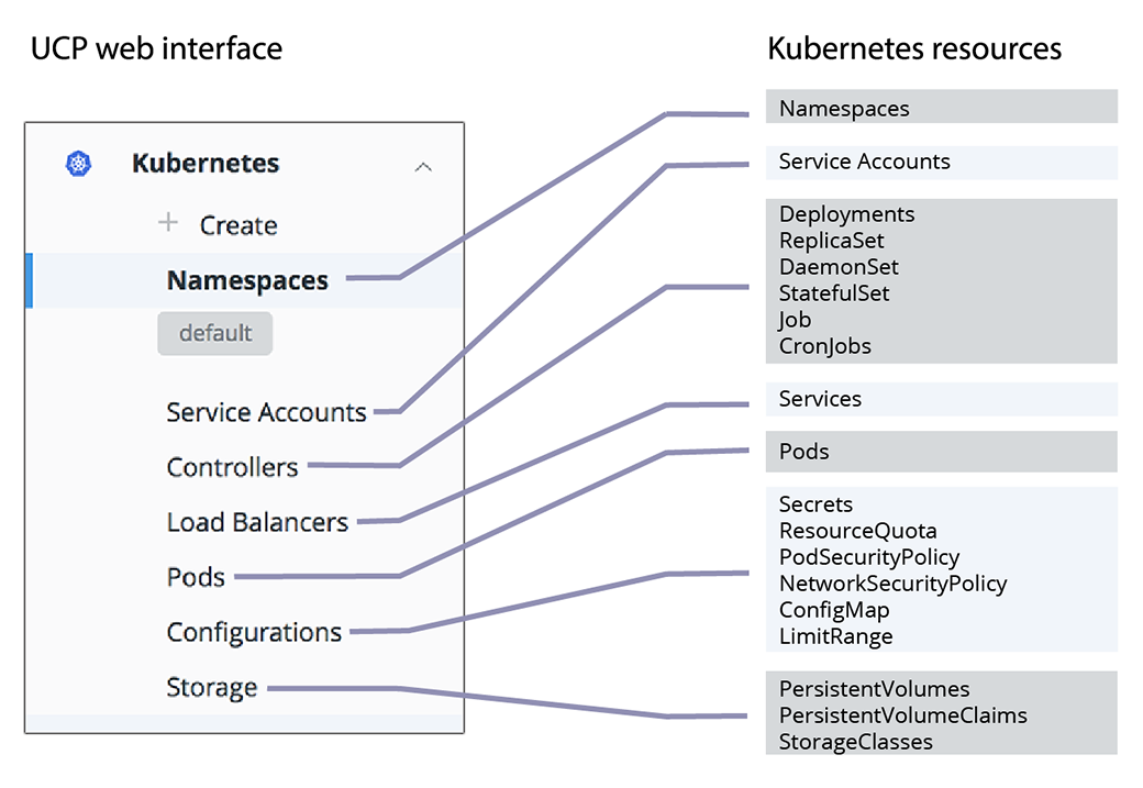
Deploying a workload to a Kubernetes cluster
You can use the MKE web UI to deploy your Kubernetes YAML files. In most cases, modifications are not necessary to deploy on a cluster managed by Docker Enterprise.
Deploy an NGINX server
In this example, a simple Kubernetes Deployment object for an NGINX server is defined in a YAML file.
apiVersion: apps/v1beta2
kind: Deployment
metadata:
name: nginx-deployment
spec:
selector:
matchLabels:
app: nginx
replicas: 2
template:
metadata:
labels:
app: nginx
spec:
containers:
- name: nginx
image: nginx:1.7.9
ports:
- containerPort: 80
This YAML file specifies an earlier version of NGINX, which will be updated in a later section.
To create the YAML file:
- Navigate to the MKE web UI, and from the left pane, click Kubernetes.
- Click Create to open the Create Kubernetes Object page.
- From the Namespace drop-down list, select default.
- Paste the previous YAML file in the Object YAML editor.
- Click Create.
Inspect the deployment
The MKE web UI shows the status of your deployment when you click the links in the Kubernetes section of the left pane.
- From the left pane, click Controllers to see the resource controllers that Docker Enterprise created for the NGINX server.
- Click the nginx-deployment controller, and in the details pane, scroll to the Template section. This shows the values that Docker Enterprise used to create the deployment.
- From the left pane, click Pods to see the pods that are provisioned for the NGINX server. Click one of the pods, and in the details pane, scroll to the Status section to see that pod’s phase, IP address, and other properties.
Expose the server
The NGINX server is up and running, but it’s not accessible from outside
of the cluster. Create a YAML file to add a NodePort service to expose
the server on a specified port.
apiVersion: v1
kind: Service
metadata:
name: nginx
labels:
app: nginx
spec:
type: NodePort
ports:
- port: 80
nodePort: 32768
selector:
app: nginx
The service connects the cluster’s internal port 80 to the external port 32768.
To expose the server:
- Repeat the previous steps and copy-paste the YAML file that defines the
nginxservice into the Object YAML editor on the Create Kubernetes Object page. When you click Create, the Load Balancers page opens. - Click the nginx service, and in the details pane, find the Ports section.
- Click the link that’s labeled URL to view the default NGINX page.
The YAML definition connects the service to the NGINX server using
the app label nginx and a corresponding label selector.
Update the deployment
Update an existing deployment by applying an updated YAML file. In this example, the server is scaled up to four replicas and updated to a later version of NGINX.
...
spec:
progressDeadlineSeconds: 600
replicas: 4
revisionHistoryLimit: 10
selector:
matchLabels:
app: nginx
strategy:
rollingUpdate:
maxSurge: 25%
maxUnavailable: 25%
type: RollingUpdate
template:
metadata:
creationTimestamp: null
labels:
app: nginx
spec:
containers:
- image: nginx:1.8
...
- From the left pane, click Controllers and select nginx-deployment.
- In the details pane, click Configure, and in the Edit Deployment page, find the replicas: 2 entry.
- Change the number of replicas to 4, so the line reads replicas: 4.
- Find the image: nginx:1.7.9 entry and change it to image: nginx:1.8.
- Click Save to update the deployment with the new YAML file.
- From the the left pane, click Pods to view the newly created replicas.
Use the CLI to deploy Kubernetes objects
With Docker Enterprise, you deploy your Kubernetes objects on the command line
using kubectl.
Use a client bundle to configure your client tools, like Docker CLI and
kubectl to communicate with MKE instead of the local deployments you
might have running.
When you have the client bundle set up, you can deploy a Kubernetes object from the YAML file.
apiVersion: apps/v1beta2
kind: Deployment
metadata:
name: nginx-deployment
spec:
selector:
matchLabels:
app: nginx
replicas: 2
template:
metadata:
labels:
app: nginx
spec:
containers:
- name: nginx
image: nginx:1.7.9
ports:
- containerPort: 80
---
apiVersion: v1
kind: Service
metadata:
name: nginx
labels:
app: nginx
spec:
type: NodePort
ports:
- port: 80
nodePort: 32768
selector:
app: nginx
Save the previous YAML file to a file named “deployment.yaml”, and use the following command to deploy the NGINX server:
kubectl apply -f deployment.yaml
Inspect the deployment
Use the describe deployment option to inspect the deployment:
kubectl describe deployment nginx-deployment
Also, you can use the MKE web UI to see the deployment’s pods and controllers.
Update the deployment
Update an existing deployment by applying an updated YAML file.
Edit deployment.yaml and change the following lines:
- Increase the number of replicas to 4, so the line reads replicas: 4.
- Update the NGINX version by specifying image: nginx:1.8.
Save the edited YAML file to a file named “update.yaml”, and use the following command to deploy the NGINX server:
kubectl apply -f update.yaml
Check that the deployment was scaled out by listing the deployments in the cluster:
kubectl get deployments
You should see four pods in the deployment:
NAME DESIRED CURRENT UP-TO-DATE AVAILABLE AGE
nginx-deployment 4 4 4 4 2d
Check that the pods are running the updated image:
kubectl describe deployment nginx-deployment | grep -i image
You should see the currently running image:
Image: nginx:1.8
Deploying a Compose-based app to a Kubernetes cluster
Docker Enterprise enables deploying Docker Compose files to Kubernetes
clusters. Starting in Compose file version 3.3, you use the same
docker-compose.yml file that you use for Swarm deployments, but you
specify Kubernetes workloads when you deploy the stack. The result
is a true Kubernetes app.
Get access to a Kubernetes namespace
To deploy a stack to Kubernetes, you need a namespace for the app’s
resources. Contact your Docker EE administrator to get access to a
namespace. In this example, the namespace is called labs.
Create a Kubernetes app from a Compose file
In this example, you create a simple app, named “lab-words”, by using a Compose file. This assumes you are deploying onto a cloud infrastructure. The following YAML defines the stack:
version: '3.3'
services:
web:
image: dockersamples/k8s-wordsmith-web
ports:
- "8080:80"
words:
image: dockersamples/k8s-wordsmith-api
deploy:
replicas: 5
db:
image: dockersamples/k8s-wordsmith-db
In your browser, log in to
https://<mke-url>. Navigate to Shared Resources > Stacks.Click Create Stack to open up the “Create Application” page.
Under “Configure Application”, type “lab-words” for the application name.
Select Kubernetes Workloads for Orchestrator Mode.
In the Namespace drowdown, select “labs”.
Under “Application File Mode”, leave Compose File selected and click Next.
Paste the previous YAML, then click Create to deploy the stack.
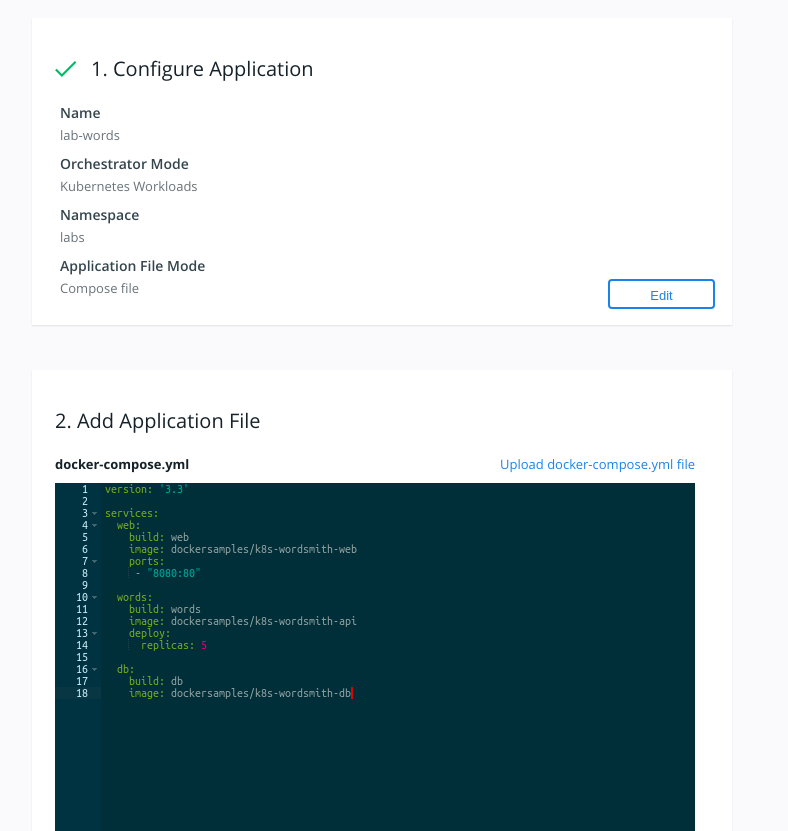
Inspect the deployment
After a few minutes have passed, all of the pods in the lab-words
deployment are running.
To inspect the deployment:
Navigate to Kubernetes > Pods. Confirm that there are seven pods and that their status is Running. If any pod has a status of Pending, wait until every pod is running.
Next, select Kubernetes > Load balancers and find the web-published service.
Click the web-published service, and scroll down to the Ports section.
Under Ports, grab the Node Port information.
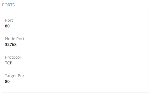
In a new tab or window, enter your cloud instance public IP Address and append
:<NodePort>from the previous step. For example, to find the public IP address of an EC2 instance, refer to Amazon EC2 Instance IP Addressing. The app is displayed.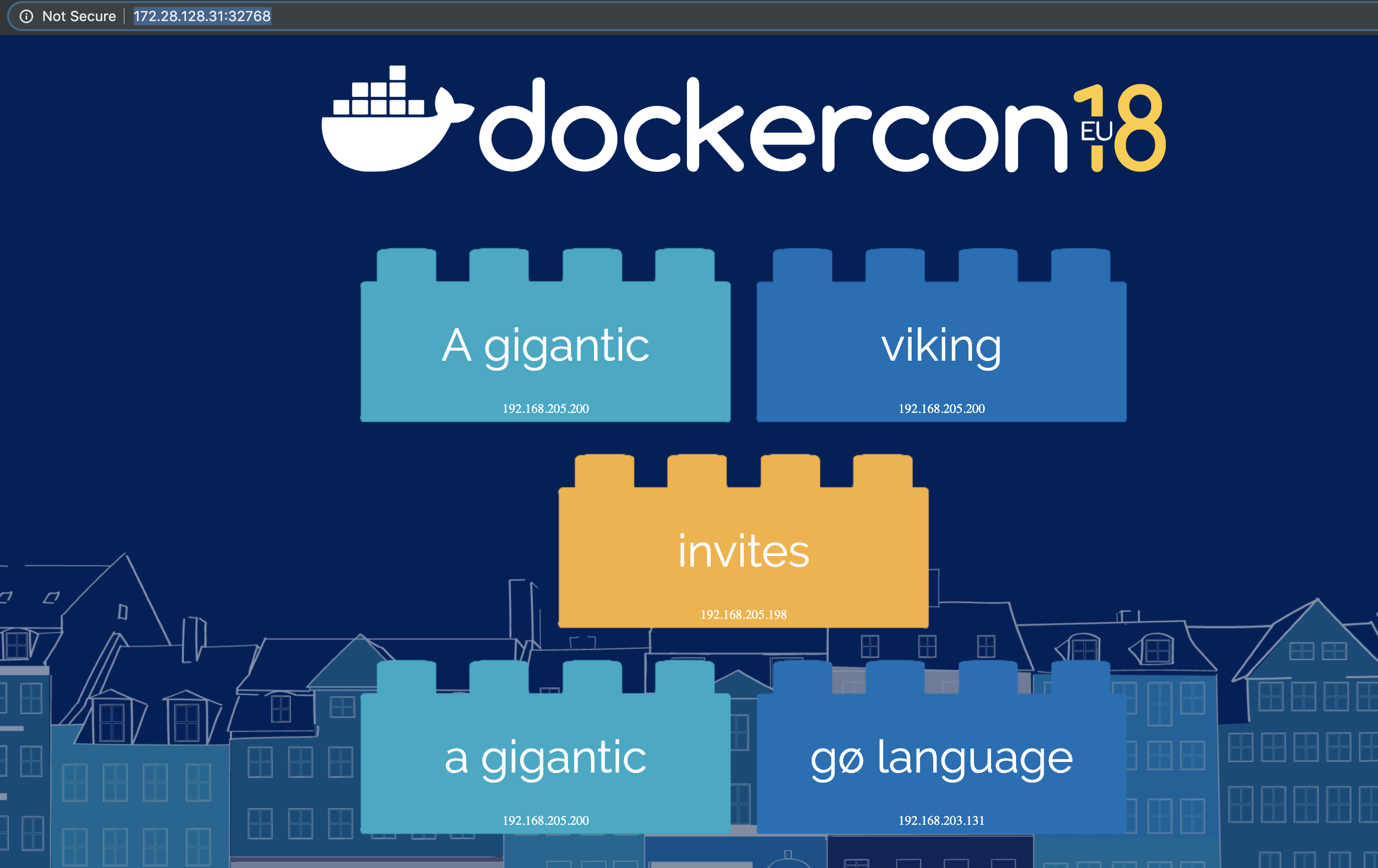
Using Pod Security Policies
Pod Security Policies (PSPs) are cluster-level resources that are enabled by default in MKE 3.2.
There are two default PSPs in MKE: a privileged policy and an
unprivileged policy. Administrators of the cluster can enforce
additional policies and apply them to users and teams for further
control of what runs in the Kubernetes cluster. This topic describes the
two default policies, and provides two example use cases for custom
policies.
Kubernetes Role Based Access Control (RBAC)
To interact with PSPs, a user will need to be granted access to the
PodSecurityPolicy object in Kubernetes RBAC. If the user is a
MKE Admin, then the user can already manipulate PSPs. A normal user
can interact with policies if a MKE admin creates the following
ClusterRole and ClusterRoleBinding:
$ cat <<EOF | kubectl create -f -
apiVersion: rbac.authorization.k8s.io/v1
kind: ClusterRole
metadata:
name: psp-admin
rules:
- apiGroups:
- extensions
resources:
- podsecuritypolicies
verbs:
- create
- delete
- get
- list
- patch
- update
EOF
$ USER=jeff
$ cat <<EOF | kubectl create -f -
apiVersion: rbac.authorization.k8s.io/v1
kind: ClusterRoleBinding
metadata:
name: psp-admin:$USER
roleRef:
kind: ClusterRole
name: psp-admin
apiGroup: rbac.authorization.k8s.io
subjects:
- kind: User
name: $USER
EOF
Default pod security policies in MKE
By default, there are two policies defined within MKE, privileged
and unprivileged. Additionally, there is a ClusterRoleBinding
that gives every single user access to the privileged policy. This is
for backward compatibility after an upgrade. By default, any user can
create any pod.
Note
PSPs do not override security defaults built into the MKE RBAC engine for Kubernetes pods. These security defaults prevent non-admin users from mounting host paths into pods or starting privileged pods.
$ kubectl get podsecuritypolicies
NAME PRIV CAPS SELINUX RUNASUSER FSGROUP SUPGROUP READONLYROOTFS VOLUMES
privileged true * RunAsAny RunAsAny RunAsAny RunAsAny false *
unprivileged false RunAsAny RunAsAny RunAsAny RunAsAny false *
Specification for the privileged policy:
allowPrivilegeEscalation: true
allowedCapabilities:
- '*'
fsGroup:
rule: RunAsAny
hostIPC: true
hostNetwork: true
hostPID: true
hostPorts:
- max: 65535
min: 0
privileged: true
runAsUser:
rule: RunAsAny
seLinux:
rule: RunAsAny
supplementalGroups:
rule: RunAsAny
volumes:
- '*'
Specification for the unprivileged policy:
allowPrivilegeEscalation: false
allowedHostPaths:
- pathPrefix: /dev/null
readOnly: true
fsGroup:
rule: RunAsAny
hostPorts:
- max: 65535
min: 0
runAsUser:
rule: RunAsAny
seLinux:
rule: RunAsAny
supplementalGroups:
rule: RunAsAny
volumes:
- '*'
Use the unprivileged policy
Note
When following this guide, if the prompt $ follows
admin, the action needs to be performed by a user with access to
create pod security policies as discussed in the Kubernetes RBAC
section. If the prompt
$ follows user, the MKE account does not need access to the
PSP object in Kubernetes. The user only needs the ability to create
Kubernetes pods.
To switch users from the privileged policy to the unprivileged
policy (or any custom policy), an admin must first remove the
ClusterRoleBinding that links all users and service accounts to the
privileged policy.
admin $ kubectl delete clusterrolebindings ucp:all:privileged-psp-role
When the ClusterRoleBinding is removed, cluster admins can still
deploy pods, and these pods are deployed with the privileged policy.
But users or service accounts are unable to deploy pods, because
Kubernetes does not know what pod security policy to apply. Note that cluster
admins would not be able to deploy deployments.
user $ kubectl apply -f pod.yaml
Error from server (Forbidden): error when creating "pod.yaml": pods "demopod" is forbidden: unable to validate against any pod security policy: []
Therefore, to allow a user or a service account to use the
unprivileged policy (or any custom policy), you must create a
RoleBinding to link that user or team with the alternative policy.
For the unprivileged policy, a ClusterRole has already been
defined, but has not been attached to a user.
# List Existing Cluster Roles
admin $ kubectl get clusterrole | grep psp
privileged-psp-role 3h47m
unprivileged-psp-role 3h47m
# Define which user to apply the ClusterRole too
admin $ USER=jeff
# Create a RoleBinding linking the ClusterRole to the User
admin $ cat <<EOF | kubectl create -f -
kind: RoleBinding
apiVersion: rbac.authorization.k8s.io/v1
metadata:
name: unprivileged-psp-role:$USER
namespace: default
roleRef:
kind: ClusterRole
name: unprivileged-psp-role
apiGroup: rbac.authorization.k8s.io
subjects:
- kind: User
name: $USER
namespace: default
EOF
In the following example, when user “jeff” deploys a basic nginx
pod, the unprivileged policy then gets applied.
user $ cat <<EOF | kubectl create -f -
apiVersion: v1
kind: Pod
metadata:
name: demopod
spec:
containers:
- name: demopod
image: nginx
EOF
user $ kubectl get pods
NAME READY STATUS RESTARTS AGE
demopod 1/1 Running 0 10m
To check which PSP is applied to a pod, you can get a detailed view of
the pod spec using the -o yaml or -o json syntax with
kubectl. You can parse JSON output with jq.
user $ kubectl get pods demopod -o json | jq -r '.metadata.annotations."kubernetes.io/psp"'
unprivileged
Using the unprivileged policy in a deployment
Note
In most use cases, a Pod is not actually scheduled by a user. When creating Kubernetes objects such as Deployments or Daemonsets, the pods are scheduled by a service account or a controller.
If you have disabled the privileged PSP policy, and created a
RoleBinding to map a user to a new PSP policy, Kubernetes objects
like Deployments and Daemonsets will not be able to deploy pods. This is
because Kubernetes objects, like Deployments, use a Service Account
to schedule pods, instead of the user that created the Deployment.
user $ kubectl get deployments
NAME READY UP-TO-DATE AVAILABLE AGE
nginx 0/1 0 0 88s
user $ kubectl get replicasets
NAME DESIRED CURRENT READY AGE
nginx-cdcdd9f5c 1 0 0 92s
user $ kubectl describe replicasets nginx-cdcdd9f5c
...
Warning FailedCreate 48s (x15 over 2m10s) replicaset-controller Error creating: pods "nginx-cdcdd9f5c-" is forbidden: unable to validate against any pod security policy: []
For this deployment to be able to schedule pods, the service account defined wthin the deployment specification needs to be associated with a PSP policy. If a service account is not defined within a deployment spec, the default service account in a namespace is used.
This is the case in the deployment output above. As there is no service
account defined, a Rolebinding is needed to grant the default
service account in the default namespace to use the PSP policy.
Example RoleBinding to associate the unprivileged PSP policy
in MKE with the defaut service account in the default namespace:
admin $ cat <<EOF | kubectl create -f -
kind: RoleBinding
apiVersion: rbac.authorization.k8s.io/v1
metadata:
name: unprivileged-psp-role:defaultsa
namespace: default
roleRef:
kind: ClusterRole
name: unprivileged-psp-role
apiGroup: rbac.authorization.k8s.io
subjects:
- kind: ServiceAccount
name: default
namespace: default
EOF
To allow the replica set to schedule pods within the cluster:
user $ kubectl get deployments
NAME READY UP-TO-DATE AVAILABLE AGE
nginx 1/1 1 1 6m11s
user $ kubectl get replicasets
NAME DESIRED CURRENT READY AGE
nginx-cdcdd9f5c 1 1 1 6m16s
user $ kubectl get pods
NAME READY STATUS RESTARTS AGE
nginx-cdcdd9f5c-9kknc 1/1 Running 0 6m17s
user $ kubectl get pod nginx-cdcdd9f5c-9kknc -o json | jq -r '.metadata.annotations."kubernetes.io/psp"'
unprivileged
Applying the unprivileged PSP policy to a namespace
A common use case when using PSPs is to apply a particular policy to one
namespace, but not configure the rest. An example could be where an
admin might be want to configure keep the privileged policy for all
of the infrastructure namespaces but configure the unprivileged
policy for the end user namespaces. This can be done with the following
example:
In this demonstration cluster, infrastructure workloads are deployed in
the kube-system and the monitoring namespaces. End User
workloads are deployed in the default namespace.
admin $ kubectl get namespaces
NAME STATUS AGE
default Active 3d
kube-node-lease Active 3d
kube-public Active 3d
kube-system Active 3d
monitoring Active 3d
First, delete the ClusterRoleBinding that is applied by default in
MKE.
admin $ kubectl delete clusterrolebindings ucp:all:privileged-psp-role
Next, create a new ClusterRoleBinding that will enforce the
privileged PSP policy for all users and service accounts in the
kube-system and monitoring namespaces, where in this example
cluster the infrastructure workloads are deployed.
admin $ cat <<EOF | kubectl create -f -
apiVersion: rbac.authorization.k8s.io/v1
kind: ClusterRoleBinding
metadata:
name: ucp:infrastructure:privileged-psp-role
roleRef:
apiGroup: rbac.authorization.k8s.io
kind: ClusterRole
name: privileged-psp-role
subjects:
- kind: Group
name: system:authenticated:kube-system
apiGroup: rbac.authorization.k8s.io
- kind: Group
name: system:authenticated:monitoring
apiGroup: rbac.authorization.k8s.io
- kind: Group
name: system:serviceaccounts:kube-system
apiGroup: rbac.authorization.k8s.io
- kind: Group
name: system:serviceaccounts:monitoring
apiGroup: rbac.authorization.k8s.io
EOF
Finally, create a ClusterRoleBinding to allow all users who deploy
pods and deployments in the default namespace to use the
unprivileged policy.
admin $ cat <<EOF | kubectl create -f -
apiVersion: rbac.authorization.k8s.io/v1
kind: ClusterRoleBinding
metadata:
name: ucp:default:unprivileged-psp-role
roleRef:
apiGroup: rbac.authorization.k8s.io
kind: ClusterRole
name: unprivileged-psp-role
subjects:
- kind: Group
name: system:authenticated:default
apiGroup: rbac.authorization.k8s.io
- kind: Group
name: system:serviceaccounts:default
apiGroup: rbac.authorization.k8s.io
EOF
Now when the user deploys in the default namespace they will get the
unprivileged policy but when they deploy in the monitoring namespace
they will get the privileged policy.
user $ cat <<EOF | kubectl create -f -
apiVersion: v1
kind: Pod
metadata:
name: demopod
namespace: monitoring
spec:
containers:
- name: demopod
image: nginx
---
apiVersion: v1
kind: Pod
metadata:
name: demopod
namespace: default
spec:
containers:
- name: demopod
image: nginx
EOF
user $ kubectl get pods demopod -n monitoring -o json | jq -r '.metadata.annotations."kubernetes.io/psp"'
privileged
user $ kubectl get pods demopod -n default -o json | jq -r '.metadata.annotations."kubernetes.io/psp"'
unprivileged
Reenable the privileged PSP for all users
To revert to the default MKE configuration, in which all MKE users and
service accounts use the privileged PSP, recreate the default
ClusterRoleBinding:
admin $ cat <<EOF | kubectl create -f -
apiVersion: rbac.authorization.k8s.io/v1
kind: ClusterRoleBinding
metadata:
name: ucp:all:privileged-psp-role
roleRef:
apiGroup: rbac.authorization.k8s.io
kind: ClusterRole
name: privileged-psp-role
subjects:
- kind: Group
name: system:authenticated
apiGroup: rbac.authorization.k8s.io
- kind: Group
name: system:serviceaccounts
apiGroup: rbac.authorization.k8s.io
EOF
PSP examples
MKE admins or users with the correct permissions can create their own custom policies and attach them to MKE users or teams. This section highlights two potential use cases for custom PSPs. These two uses cases can be combined into the same policy. Note there are many more use cases with PSPs not covered in this document.
- Preventing containers that start as the Root User
- Applying default seccomp policies to all Kubernetes Pods
Example 1: Use a PSP to enforce “no root users”
A common use case for PSPs is to prevent a user from deploying
containers that run with the root user. A PSP can be created to enforce
this with the parameter MustRunAsNonRoot.
admin $ cat <<EOF | kubectl create -f -
apiVersion: extensions/v1beta1
kind: PodSecurityPolicy
metadata:
name: norootcontainers
spec:
allowPrivilegeEscalation: false
allowedHostPaths:
- pathPrefix: /dev/null
readOnly: true
fsGroup:
rule: RunAsAny
hostPorts:
- max: 65535
min: 0
runAsUser:
rule: MustRunAsNonRoot
seLinux:
rule: RunAsAny
supplementalGroups:
rule: RunAsAny
volumes:
- '*'
EOF
If not done previously, the admin user must remove the
ClusterRoleBinding for the privileged policy, and then add a new
ClusterRole and RoleBinding to link a user to the new
norootcontainers policy.
# Delete the default privileged ClusterRoleBinding
admin $ kubectl delete clusterrolebindings ucp:all:privileged-psp-role
# Create a ClusterRole Granting Access to the Policy
admin $ cat <<EOF | kubectl create -f -
apiVersion: rbac.authorization.k8s.io/v1
kind: ClusterRole
metadata:
name: norootcontainers-psp-role
rules:
- apiGroups:
- policy
resourceNames:
- norootcontainers
resources:
- podsecuritypolicies
verbs:
- use
EOF
# Define a User to attach to the No Root Policy
admin $ USER=jeff
# Create a RoleBinding attaching the User to the ClusterRole
admin $ cat <<EOF | kubectl create -f -
kind: RoleBinding
apiVersion: rbac.authorization.k8s.io/v1
metadata:
name: norootcontainers-psp-role:$USER
namespace: default
roleRef:
kind: ClusterRole
name: norootcontainers-psp-role
apiGroup: rbac.authorization.k8s.io
subjects:
- kind: User
name: $USER
namespace: default
EOF
If a user tries to deploy a pod that runs as a root user, such as the
upstream nginx image, this should fail with a ConfigError.
user $ cat <<EOF | kubectl create -f -
apiVersion: v1
kind: Pod
metadata:
name: demopod
spec:
containers:
- name: demopod
image: nginx
EOF
user $ kubectl get pods
NAME READY STATUS RESTARTS AGE
demopod 0/1 CreateContainerConfigError 0 37s
user $ kubectl describe pods demopod
<..>
Error: container has runAsNonRoot and image will run as root
Example 2: Use a PSP to apply seccomp policies
A second use case for PSPs is to prevent a user from deploying containers without a seccomp policy. By default, Kubernetes does not apply a seccomp policy to pods, so a default seccomp policy could be applied for all pods by a PSP.
admin $ cat <<EOF | kubectl create -f -
apiVersion: extensions/v1beta1
kind: PodSecurityPolicy
metadata:
name: seccomppolicy
annotations:
seccomp.security.alpha.kubernetes.io/allowedProfileNames: 'docker/default'
seccomp.security.alpha.kubernetes.io/defaultProfileName: 'docker/default'
spec:
allowPrivilegeEscalation: false
allowedHostPaths:
- pathPrefix: /dev/null
readOnly: true
fsGroup:
rule: RunAsAny
hostPorts:
- max: 65535
min: 0
runAsUser:
rule: RunAsAny
seLinux:
rule: RunAsAny
supplementalGroups:
rule: RunAsAny
volumes:
- '*'
EOF
If not done previously, the admin user must remove the
ClusterRoleBinding for the privileged policy, and then add a new
ClusterRole and RoleBinding to link a user to the new
applyseccompprofile policy.
# Delete the default privileged ClusterRoleBinding
admin $ kubectl delete clusterrolebindings ucp:all:privileged-psp-role
# Create a ClusterRole Granting Access to the Policy
admin $ cat <<EOF | kubectl create -f -
apiVersion: rbac.authorization.k8s.io/v1
kind: ClusterRole
metadata:
name: applyseccompprofile-psp-role
rules:
- apiGroups:
- policy
resourceNames:
- seccomppolicy
resources:
- podsecuritypolicies
verbs:
- use
EOF
# Define a User to attach to the No Root Policy
admin $ USER=jeff
# Create a RoleBinding attaching the User to the ClusterRole
admin $ cat <<EOF | kubectl create -f -
kind: RoleBinding
apiVersion: rbac.authorization.k8s.io/v1
metadata:
name: applyseccompprofile-psp-role:$USER
namespace: default
roleRef:
kind: ClusterRole
name: applyseccompprofile-psp-role
apiGroup: rbac.authorization.k8s.io
subjects:
- kind: User
name: $USER
namespace: default
EOF
As shown in the following example, if a user tries to deploy an
nginx pod without applying a seccomp policy as the pod metadata,
Kubernetes automatically applies a policy for the user.
user $ cat <<EOF | kubectl create -f -
apiVersion: v1
kind: Pod
metadata:
name: demopod
spec:
containers:
- name: demopod
image: nginx
EOF
user $ kubectl get pods
NAME READY STATUS RESTARTS AGE
demopod 1/1 Running 0 16s
user $ kubectl get pods demopod -o json | jq '.metadata.annotations."seccomp.security.alpha.kubernetes.io/pod"'
"docker/default"
Creating a service account for a Kubernetes app
Kubernetes enables access control for workloads by providing service
accounts. A service account represents an identity for processes that
run in a pod. When a process is authenticated through a service account,
it can contact the API server and access cluster resources. If a pod
doesn’t have an assigned service account, it gets the default
service account.
In Docker Enterprise, you give a service account access to cluster resources by creating a grant, the same way that you would give access to a user or a team.
In this example, you will create a service account and a grant that could be used for an NGINX server.
Create the Kubernetes namespace
A Kubernetes user account is global, but a service account is scoped to a namespace, so you need to create a namespace before you create a service account.
Navigate to the Namespaces page and click Create.
In the Object YAML editor, append the following text.
metadata: name: nginx
Click Create.
In the nginx namespace, click the More options icon, and in the context menu, select Set Context, and click Confirm.
Click the Set context for all namespaces toggle and click Confirm.
Create a service account
Create a service account named nginx-service-account in the
nginx namespace.
Navigate to the Service Accounts page and click Create.
In the Namespace dropdown, select nginx.
In the Object YAML editor, paste the following text.
yaml apiVersion: v1 kind: ServiceAccount metadata: name: nginx-service-account
Click Create.
Create a grant
To give the service account access to cluster resources, create a grant
with Restricted Control permissions.
Navigate to the Grants page and click Create Grant.
In the left pane, click Resource Sets, and in the Type section, click Namespaces.
Select the nginx namespace.
In the left pane, click Roles. In the Role dropdown, select Restricted Control.
In the left pane, click Subjects, and select Service Account.
Important
The Service Account option in the Subject Type section appears only when a Kubernetes namespace is present.
In the Namespace dropdown, select nginx, and in the Service Account dropdown, select nginx-service-account.
Click Create.
Now nginx-service-account has access to all cluster resources that
are assigned to the nginx namespace.
Installing an unmanaged CNI plugin
For MKE, Calico provides the secure networking functionality for container-to-container communication within Kubernetes. MKE handles the lifecycle of Calico and packages it with MKE installation and upgrade. Additionally, the Calico deployment included with MKE is fully supported with Docker providing guidance on the container network interface (CNI) components.
At install time, MKE can be configured to install an alternative CNI plugin to support alternative use cases. The alternative CNI plugin may be certified by Docker and its partners, and published on Docker Hub. MKE components are still fully supported by Docker and respective partners. Docker will provide pointers to basic configuration, however for additional guidance on managing third-party CNI components, the platform operator will need to refer to the partner documentation or contact that third party.
MKE does manage the version or configuration of alternative CNI plugins. MKE upgrade will not upgrade or reconfigure alternative CNI plugins. To switch between managed and unmanaged CNI plugins or vice versa, you must uninstall and then reinstall MKE.
Install an unmanaged CNI plugin on MKE
Once a platform operator has complied with MKE system
requirements and taken
into consideration any requirements for the custom CNI plugin, you can
run the MKE install command with
the --unmanaged-cni flag to bring up the platform.
This command will install MKE, and bring up components like the user
interface and the RBAC engine. MKE components that require Kubernetes
Networking, such as Metrics, will not start and will stay in a
Container Creating state in Kubernetes until a CNI is installed.
Install MKE without a CNI plugin
Once connected to a manager node with Docker Enterprise
installed, you are ready to install MKE with the --unmanaged-cni
flag.
docker container run --rm -it --name ucp \
-v /var/run/docker.sock:/var/run/docker.sock \
docker/ucp:3.2.5 install \
--host-address <node-ip-address> \
--unmanaged-cni \
--interactive
Once the installation is complete, you can access MKE from a web browser. Note
that the manager node will be unhealthy as the kubelet
will report NetworkPluginNotReady. Additionally, the metrics in the
MKE dashboard will also be unavailable, as this runs in a Kubernetes
pod.
Configure CLI access to MKE
Next, a platform operator should log in to MKE, download a MKE client
bundle, and configure the Kubernetes CLI tool, kubectl.
With kubectl, you can see that the MKE components running on
Kubernetes are still pending, waiting for a CNI driver before becoming
available.
$ kubectl get nodes
NAME STATUS ROLES AGE VERSION
manager-01 NotReady master 10m v1.11.9-docker-1
$ kubectl get pods -n kube-system -o wide
NAME READY STATUS RESTARTS AGE IP NODE NOMINATED NODE
compose-565f7cf9ff-gq2gv 0/1 Pending 0 10m <none> <none> <none>
compose-api-574d64f46f-r4c5g 0/1 Pending 0 10m <none> <none> <none>
kube-dns-6d96c4d9c6-8jzv7 0/3 Pending 0 10m <none> <none> <none>
ucp-metrics-nwt2z 0/3 ContainerCreating 0 10m <none> manager-01 <none>
Install an unmanaged CNI plugin
You can usekubectl to install a custom CNI plugin on MKE.
Alternative CNI plugins are Weave, Flannel, Canal, Romana and many more.
Platform operators have complete flexibility on what to install, but
Docker will not support the CNI plugin.
The steps for installing a CNI plugin typically include:
- Downloading the relevant upstream CNI binaries.
- Placing them in
/opt/cni/bin. - Downloading the relevant CNI plugin’s Kubernetes Manifest YAML file.
- Running
$ kubectl apply -f <your-custom-cni-plugin>.yaml
Follow the CNI plugin documentation for specific installation instructions.
Note
While troubleshooting a custom CNI plugin, you may wish to access
logs within the kubelet. Connect to a MKE manager node and run
$ docker logs ucp-kubelet.
Verify the MKE installation
Upon successful installation of the CNI plugin, the related MKE
components should have a Running status as pods start to become
available.
$ kubectl get pods -n kube-system -o wide
NAME READY STATUS RESTARTS AGE IP NODE NOMINATED NODE
compose-565f7cf9ff-gq2gv 1/1 Running 0 21m 10.32.0.2 manager-01 <none>
compose-api-574d64f46f-r4c5g 1/1 Running 0 21m 10.32.0.3 manager-01 <none>
kube-dns-6d96c4d9c6-8jzv7 3/3 Running 0 22m 10.32.0.5 manager-01 <none>
ucp-metrics-nwt2z 3/3 Running 0 22m 10.32.0.4 manager-01 <none>
weave-net-wgvcd 2/2 Running 0 8m 172.31.6.95 manager-01 <none>
Note
The above example deployment uses Weave. If you are using an alternative CNI plugin, look for the relevant name and review its status.
Kubernetes network encryption
Docker Enterprise provides data-plane level IPSec network encryption to securely encrypt application traffic in a Kubernetes cluster. This secures application traffic within a cluster when running in untrusted infrastructure or environments. It is an optional feature of MKE that is enabled by deploying the SecureOverlay components on Kubernetes when using the default Calico driver for networking configured for IPIP tunneling (the default configuration).
Kubernetes network encryption is enabled by two components in MKE:
- SecureOverlay Agent
- SecureOverlay Master
The agent is deployed as a per-node service that manages the encryption state of the data plane. The agent controls the IPSec encryption on Calico’s IPIP tunnel traffic between different nodes in the Kubernetes cluster. The master is the second component, deployed on a MKE manager node, which acts as the key management process that configures and periodically rotates the encryption keys.
Kubernetes network encryption uses AES Galois Counter Mode (AES-GCM) with 128-bit keys by default. Encryption is not enabled by default and requires the SecureOverlay Agent and Master to be deployed on MKE to begin encrypting traffic within the cluster. It can be enabled or disabled at any time during the cluster lifecycle. However, it should be noted that it can cause temporary traffic outages between pods during the first few minutes of traffic enabling/disabling. When enabled, Kubernetes pod traffic between hosts is encrypted at the IPIP tunnel interface in the MKE host.
Requirements
Kubernetes network encryption is supported for the following platforms:
- Docker Enterprise 2.1+ (MKE 3.1+)
- Kubernetes 1.11+
- On-premise, AWS, GCE
- Azure is not supported for network encryption as encryption utilizes
- Calico’s IPIP tunnel
- Only supported when using MKE’s default Calico CNI plugin
- Supported on all Docker Enterprise supported Linux OSes
Configuring MTUs
Before deploying the SecureOverlay components, ensure that Calico is configured so that the IPIP tunnel MTU maximum transmission unit (MTU), or the largest packet length that the container will allow, leaves sufficient headroom for the encryption overhead. Encryption adds 26 bytes of overhead, but every IPSec packet size must be a multiple of 4 bytes. IPIP tunnels require 20 bytes of encapsulation overhead. The IPIP tunnel interface MTU must be no more than “EXTMTU - 46 - ((EXTMTU - 46) modulo 4)”, where EXTMTU is the minimum MTU of the external interfaces. An IPIP MTU of 1452 should generally be safe for most deployments.
Changing MKE’s MTU requires updating the MKE configuration.
Update the following values to the new MTU:
[cluster_config]
...
calico_mtu = "1452"
ipip_mtu = "1452"
...
Configuring SecureOverlay
SecureOverlay allows you to enable IPSec network encryption in Kubernetes. Once the cluster nodes’ MTUs are properly configured, deploy the SecureOverlay components using the SecureOverlay YAML file to MKE.
Beginning with MKE 3.2.4, you can configure SecureOverlay in one of two ways:
- Using the MKE configuration file
- Using the SecureOverlay YAML file
Using the MKE configuration file
- Add
secure-overlayto the MKE configuration file. - Set to``true`` to enable IPSec network encryption. The default is``false``.
Using the SecureOverlay YAML file
Download the SecureOverlay YAML file.
Issue the following command from any machine with the properly configured kubectl environment and the proper MKE bundle’s credentials:
$ kubectl apply -f ucp-secureoverlay.yml
Run this command at cluster installation time before starting any workloads.
To remove the encryption from the system, issue the following command:
$ kubectl delete -f ucp-secureoverlay.yml
Persistent Kubernetes Storage
Using NFS Storage
Users can provide persistent storage for workloads running on Docker Enterprise by using NFS storage. These NFS shares, when mounted into the running container, provide state to the application, managing data external to the container’s lifecycle.
Note
Provisioning an NFS server and exporting an NFS share are out of scope for this guide. Additionally, using external Kubernetes plugins to dynamically provision NFS shares, is also out of scope for this guide.
There are two options to mount existing NFS shares within Kubernetes Pods:
- Define NFS shares within the Pod definitions. NFS shares are defined manually by each tenant when creating a workload.
- Define NFS shares as a Cluster object through Persistent Volumes, with the Cluster object lifecycle handled separately from the workload. This is common for operators who want to define a range of NFS shares for tenants to request and consume.
Using Azure Disk Storage
Platform operators can provide persistent storage for workloads running on Docker Enterprise and Microsoft Azure by using Azure Disk. Platform operators can either pre-provision Azure Disks to be consumed by Kubernetes Pods, or can use the Azure Kubernetes integration to dynamically provision Azure Disks on demand.
Prerequisites
This guide assumes you have already provisioned a MKE environment on Microsoft Azure. The Cluster must be provisioned after meeting all of the prerequisites listed in Install MKE on Azure.
Additionally, this guide uses the Kubernetes Command Line tool
$ kubectl to provision Kubernetes objects within a MKE cluster.
Therefore, this tool must be downloaded, along with a MKE client bundle.
Manually provision Azure Disks
An operator can use existing Azure Disks or manually provision new ones to provide persistent storage for Kubernetes Pods. Azure Disks can be manually provisioned in the Azure Portal, using ARM Templates or the Azure CLI. The following example uses the Azure CLI to manually provision an Azure Disk.
$ RG=myresourcegroup
$ az disk create \
--resource-group $RG \
--name k8s_volume_1 \
--size-gb 20 \
--query id \
--output tsv
Using the Azure CLI command in the previous example should return the Azure ID of the Azure Disk Object. If you are provisioning Azure resources using an alternative method, make sure you retrieve the Azure ID of the Azure Disk, because it is needed for another step.
/subscriptions/<subscriptionID>/resourceGroups/<resourcegroup>/providers/Microsoft.Compute/disks/<diskname>
You can now create Kubernetes Objects that refer to this Azure Disk. The following example uses a Kubernetes Pod. However, the same Azure Disk syntax can be used for DaemonSets, Deployments, and StatefulSets. In the following example, the Azure Disk Name and ID reflect the manually created Azure Disk.
$ cat <<EOF | kubectl create -f -
apiVersion: v1
kind: Pod
metadata:
name: mypod-azuredisk
spec:
containers:
- image: nginx
name: mypod
volumeMounts:
- name: mystorage
mountPath: /data
volumes:
- name: mystorage
azureDisk:
kind: Managed
diskName: k8s_volume_1
diskURI: /subscriptions/<subscriptionID>/resourceGroups/<resourcegroup>/providers/Microsoft.Compute/disks/<diskname>
EOF
Dynamically provision Azure Disks
Kubernetes can dynamically provision Azure Disks using the Azure Kubernetes integration, which was configured when MKE was installed. For Kubernetes to determine which APIs to use when provisioning storage, you must create Kubernetes Storage Classes specific to each storage backend.
In Azure, there are two different Azure Disk types that can be consumed by Kubernetes: Azure Disk Standard Volumes and Azure Disk Premium Volumes.
Depending on your use case, you can deploy one or both of the Azure Disk storage Classes (Standard and Advanced).
To create a Standard Storage Class:
$ cat <<EOF | kubectl create -f -
kind: StorageClass
apiVersion: storage.k8s.io/v1
metadata:
name: standard
provisioner: kubernetes.io/azure-disk
parameters:
storageaccounttype: Standard_LRS
kind: Managed
EOF
To Create a Premium Storage Class:
$ cat <<EOF | kubectl create -f -
kind: StorageClass
apiVersion: storage.k8s.io/v1
metadata:
name: premium
provisioner: kubernetes.io/azure-disk
parameters:
storageaccounttype: Premium_LRS
kind: Managed
EOF
To determine which Storage Classes have been provisioned:
$ kubectl get storageclasses
NAME PROVISIONER AGE
premium kubernetes.io/azure-disk 1m
standard kubernetes.io/azure-disk 1m
After you create a Storage Class, you can use Kubernetes Objects to dynamically provision Azure Disks. This is done using Kubernetes Persistent Volumes Claims.
The following example uses the standard storage class and creates a 5 GiB Azure Disk. Alter these values to fit your use case.
$ cat <<EOF | kubectl create -f -
kind: PersistentVolumeClaim
apiVersion: v1
metadata:
name: azure-disk-pvc
spec:
storageClassName: standard
accessModes:
- ReadWriteOnce
resources:
requests:
storage: 5Gi
EOF
At this point, you should see a new Persistent Volume Claim and Persistent Volume inside of Kubernetes. You should also see a new Azure Disk created in the Azure Portal.
$ kubectl get persistentvolumeclaim
NAME STATUS VOLUME CAPACITY ACCESS MODES STORAGECLASS AGE
azure-disk-pvc Bound pvc-587deeb6-6ad6-11e9-9509-0242ac11000b 5Gi RWO standard 1m
$ kubectl get persistentvolume
NAME CAPACITY ACCESS MODES RECLAIM POLICY STATUS CLAIM STORAGECLASS REASON AGE
pvc-587deeb6-6ad6-11e9-9509-0242ac11000b 5Gi RWO Delete Bound default/azure-disk-pvc standard 3m
Now that a Kubernetes Persistent Volume has been created, you can mount this into a Kubernetes Pod. The disk can be consumed by any Kubernetes object type, including a Deployment, DaemonSet, or StatefulSet. However, the following example just mounts the persistent volume into a standalone pod.
$ cat <<EOF | kubectl create -f -
kind: Pod
apiVersion: v1
metadata:
name: mypod-dynamic-azuredisk
spec:
containers:
- name: mypod
image: nginx
ports:
- containerPort: 80
name: "http-server"
volumeMounts:
- mountPath: "/usr/share/nginx/html"
name: storage
volumes:
- name: storage
persistentVolumeClaim:
claimName: azure-disk-pvc
EOF
In Azure, there are limits to the number of data disks that can be attached to each Virtual Machine. This data is shown in Azure Virtual Machine Sizes. Kubernetes is aware of these restrictions, and prevents pods from deploying on Nodes that have reached their maximum Azure Disk Capacity.
This can be seen if a pod is stuck in the ContainerCreating stage:
$ kubectl get pods
NAME READY STATUS RESTARTS AGE
mypod-azure-disk 0/1 ContainerCreating 0 4m
Describing the pod displays troubleshooting logs, showing the node has reached its capacity:
$ kubectl describe pods mypod-azure-disk
<...>
Warning FailedAttachVolume 7s (x11 over 6m) attachdetach-controller AttachVolume.Attach failed for volume "pvc-6b09dae3-6ad6-11e9-9509-0242ac11000b" : Attach volume "kubernetes-dynamic-pvc-6b09dae3-6ad6-11e9-9509-0242ac11000b" to instance "/subscriptions/<sub-id>/resourceGroups/<rg>/providers/Microsoft.Compute/virtualMachines/worker-03" failed with compute.VirtualMachinesClient#CreateOrUpdate: Failure sending request: StatusCode=409 -- Original Error: failed request: autorest/azure: Service returned an error. Status=<nil> Code="OperationNotAllowed" Message="The maximum number of data disks allowed to be attached to a VM of this size is 4." Target="dataDisks"
Using Azure Files Storage
Platform operators can provide persistent storage for workloads running on Docker Enterprise and Microsoft Azure by using Azure Files. You can either pre-provision Azure Files Shares to be consumed by Kubernetes Pods or can you use the Azure Kubernetes integration to dynamically provision Azure Files Shares on demand.
Prerequisites
This guide assumes you have already provisioned a MKE environment on Microsoft Azure. The cluster must be provisioned after meeting all prerequisites listed in Install MKE on Azure.
Additionally, this guide uses the Kubernetes Command Line tool
$ kubectl to provision Kubernetes objects within a MKE cluster.
Therefore, you must download this tool along with a MKE client bundle.
Manually Provisioning Azure Files
You can use existing Azure Files Shares or manually provision new ones to provide persistent storage for Kubernetes Pods. Azure Files Shares can be manually provisioned in the Azure Portal using ARM Templates or using the Azure CLI. The following example uses the Azure CLI to manually provision Azure Files Shares.
When manually creating an Azure Files Share, first create an Azure Storage Account for the file shares. If you have already provisioned a Storage Account, you can skip to “Creating an Azure Files Share.”
Note
The Azure Kubernetes Driver does not support Azure Storage Accounts created using Azure Premium Storage.
$ REGION=ukwest
$ SA=mystorageaccount
$ RG=myresourcegroup
$ az storage account create \
--name $SA \
--resource-group $RG \
--location $REGION \
--sku Standard_LRS
After a File Share has been created, you must load the Azure Storage Account Access key as a Kubernetes Secret into MKE. This provides access to the file share when Kubernetes attempts to mount the share into a pod. This key can be found in the Azure Portal or retrieved as shown in the following example by the Azure CLI.
$ SA=mystorageaccount
$ RG=myresourcegroup
$ FS=myfileshare
# The Azure Storage Account Access Key can also be found in the Azure Portal
$ STORAGE_KEY=$(az storage account keys list --resource-group $RG --account-name $SA --query "[0].value" -o tsv)
$ kubectl create secret generic azure-secret \
--from-literal=azurestorageaccountname=$SA \
--from-literal=azurestorageaccountkey=$STORAGE_KEY
Using AWS EBS Storage
AWS Elastic Block Store (EBS) can be deployed with Kubernetes in Docker Enterprise 2.1 to use AWS volumes as peristent storage for applications. Before using EBS volumes, configure MKE and the AWS infrastructure for storage orchestration to function.
Configure AWS infrastructure for Kubernetes
Kubernetes Cloud Providers rovide a method of provisioning cloud resources
through Kubernetes via he --cloud-provider option. In AWS, this flag
allows the provisioning of EBS volumes and cloud load balancers.
Configuring a cluster for AWS requires several specific configuration parameters in the infrastructure before installing MKE.
Instances must have the following AWS Identity and Access permissions configured to provision EBS volumes through Kubernetes PVCs.
| Master | Worker |
|---|---|
| ec2:DescribeInstances | ec2:DescribeInstances |
| ec2:AttachVolume | ec2:AttachVolume |
| ec2:DetachVolume | ec2:DetachVolume |
| ec2:DescribeVolumes | ec2:DescribeVolumes |
| ec2:CreateVolume | ec2:DescribeSecurityGroups |
| ec2:DeleteVolume | |
| ec2:CreateTags | |
| ec2:DescribeSecurityGroups |
- Apply the roles and policies to Kubernetes masters and workers as indicated in the above chart.
- Set the hostname of the EC2 instances to the private DNS hostname of the instance.
- Change the system hostname without a public DNS name.
- Label the EC2 instances with the key
KubernetesClusterand assign the same value across all nodes, for example,UCPKubenertesCluster.
- In addition to your existing install flags, the cloud provider
flag
--cloud-provider=awsis required at install time. - The cloud provider can also be enabled post-install through the MKE configuration.
- The
ucp-agentneeds to be updated to propogate the new configuration.
[cluster_config]
...
cloud_provider = "aws"
Deploy AWS EBS Volumes
After configuring MKE for the AWS cloud provider, you can create persistent volumes that deploy EBS volumes attached to hosts and mounted inside pods. The EBS volumes are provisioned dynamically such they are created, attached, destroyed along with the lifecycle of the persistent volumes. This does not require users to directly access to the AWS as you request these resources directly through Kubernetes primitives.
We recommend you use the StorageClass and PersistentVolumeClaim
resources as these abstraction layers provide more portability as well
as control over the storage layer across environments.
A StorageClass lets administrators describe “classes” of storage
available in which classes map to quality-of-service levels, or backup
policies, or any policies required by cluster administrators. The
following StorageClass maps a “standard” class of storage to the
gp2 type of storage in AWS EBS.
kind: StorageClass
apiVersion: storage.k8s.io/v1
metadata:
name: standard
provisioner: kubernetes.io/aws-ebs
parameters:
type: gp2
reclaimPolicy: Retain
mountOptions:
- debug
A PersistentVolumeClaim (PVC) is a claim for storage resources that
are bound to a PersistentVolume (PV) when storage resources are
granted. The following PVC makes a request for 1Gi of storage from
the standard storage class.
kind: PersistentVolumeClaim
apiVersion: v1
metadata:
name: task-pv-claim
spec:
storageClassName: standard
accessModes:
- ReadWriteOnce
resources:
requests:
storage: 1Gi
The following Pod spec references the PVC task-pv-claim from above
which references the standard storage class in this cluster.
kind: Pod
apiVersion: v1
metadata:
name: task-pv-pod
spec:
volumes:
- name: task-pv-storage
persistentVolumeClaim:
claimName: task-pv-claim
containers:
- name: task-pv-container
image: nginx
ports:
- containerPort: 80
name: "http-server"
volumeMounts:
- mountPath: "/usr/share/nginx/html"
name: task-pv-storage
Once the pod is deployed, run the following kubectl command to
verify the PV was created and bound to the PVC.
kubectl get pv
NAME CAPACITY ACCESS MODES RECLAIM POLICY STATUS CLAIM STORAGECLASS REASON AGE
pvc-751c006e-a00b-11e8-8007-0242ac110012 1Gi RWO Retain Bound default/task-pv-claim standard 3h
The AWS console shows a volume has been provisioned having a
matching name with type gp2 and a 1GiB size.
Using vSphere Volumes
The vSphere Storage for Kubernetes driver enables customers to address persistent storage requirements for Kubernetes pods in vSphere environments. The driver allows you to create a Persistent Volume (PV) on a Virtual Machine File System (VMFS), and use it to manage persistent storage requirements independent of pod and VM lifecycle.
Note
Of the three main storage backends offered by vSphere on Kubernetes (VMFS, vSAN, and NFS), Docker supports VMFS.
You can use the vSphere Cloud Provider to manage storage with Kubernetes in MKE 3.1 and later. This includes support for:
- Volumes
- PVs
- StorageClasses and provisioning volumes
Prerequisites
- Ensure that
vsphere.confis populated according to the vSphere Cloud Provider Configuration Deployment Guide. - The
disk.EnableUUIDvalue on the worker VMs must be set toTrue. - When running Docker Enterprise 3.0, you must specify the “vm-uuid” flag in the vsphere.conf file on the MKE managers.
Configure for Kubernetes
Kubernetes cloud providers provide a method of provisioning cloud
resources through Kubernetes via the --cloud-provider option. This
is to ensure that the kubelet is aware that it must be initialized by
the ucp-kube-controller-manager before any work is scheduled.
docker container run --rm -it --name ucp -e REGISTRY_USERNAME=$REGISTRY_USERNAME -e REGISTRY_PASSWORD=$REGISTRY_PASSWORD \
-v /var/run/docker.sock:/var/run/docker.sock \
"dockereng/ucp:3.1.0-tp2" \
install \
--host-address <HOST_ADDR> \
--admin-username admin \
--admin-password XXXXXXXX \
--cloud-provider=vsphere \
--image-version latest:
Create a StorageClass
Create a StorageClass with a user specified disk format.
apiVersion: storage.k8s.io/v1 kind: StorageClass metadata: name: fast provisioner: kubernetes.io/vsphere-volume parameters: diskformat: zeroedthick
For example,
diskformatcan bethin,zeroedthick, oreagerzeroedthick. The default format isthin.Create a StorageClass with a disk format on a user-specified datastore.
apiVersion: storage.k8s.io/v1
kind: StorageClass
metadata:
name: fast
provisioner: kubernetes.io/vsphere-volume
parameters:
diskformat: zeroedthick
datastore: VSANDatastore
You can also specify the ``datastore`` in the StorageClass. The volume will
be created on the datastore specified in the StorageClass, which in this
case is ``VSANDatastore``. This field is optional. If the datastore is not
specified, then the volume will be created on the datastore specified in the
vSphere configuration file used to initialize the vSphere Cloud Provider.
Deploy vSphere Volumes
After you create a StorageClass, you can create PVs that deploy volumes attached to hosts and mounted inside pods. A PersistentVolumeClaim (PVC) is a claim for storage resources that are bound to a PV when storage resources are granted.
We recommend that you use the StorageClass and PVC resources as these abstraction layers provide more portability as well as control over the storage layer across environments.
To deploy vSphere volumes:
- Create a PVC from the plugin. When you define a PVC to use the StorageClass, a PV is created and bound.
- Create a reference to the PVC from the Pod.
- Start a Pod using the PVC that you defined.
Configuring iSCSI
Internet Small Computer System Interface (iSCSI) is an IP-based standard that provides block-level access to storage devices. iSCSI takes requests from clients and fulfills these requests on remote SCSI devices. iSCSI support in MKE enables Kubernetes workloads to consume persistent storage from iSCSI targets.
iSCSI components
The iSCSI Initiator is any client that consumes storage and sends iSCSI
commands. In a MKE cluster, the iSCSI initiator must be installed and
running on any node where pods can be scheduled. Configuration, target
discovery, and login/logout to a target are primarily performed by two
software components: iscsid (service) and iscsiadm (CLI tool).
These two components are typically packaged as part of open-iscsi on Debian
systems and iscsi-initiator-utils on RHEL/Centos/Fedora systems.
iscsidis the iSCSI initiator daemon and implements the control pathof the iSCSI protocol. It communicates with
iscsiadmand kernel modules.
iscsiadmis a CLI tool that allows discovery, login to iSCSI targets,session management, and access and management of the
open-iscsidatabase.
The iSCSI Target is any server that shares storage and receives iSCSI commands from an initiator.
Note
iSCSI kernel modules implement the data path. The most common modules used
across Linux distributions are scsi_transport_iscsi.ko,``libiscsi.ko``
and iscsi_tcp.ko. These modules need to be loaded on the host for
proper functioning of the iSCSI initiator.
Prerequisites
- Basic Kubernetes and iSCSI knowledge is assumed.
- iSCSI storage provider hardware and software set up is complete. There is no significant demand for RAM/Disk when running external provisioners in MKE clusters. For setup information specific to a storage vendor, refer to the vendor documentation.
- Kubectl must be set up on clients.
- The iSCSI server must be accessible to MKE worker nodes.
Limitations
- Not supported on Windows.
Usage
The following steps are required for configuring iSCSI in Kubernetes via MKE:
- Configure iSCSI target.
- Configure generic iSCSI initiator.
- Configure MKE.
An iSCSI target can run on dedicated/stand-alone hardware, or can be configured in a hyper-converged manner to run alongside container workloads on MKE nodes. To provide access to the storage device, each target is configured with one or more logical unit numbers (LUNs).
iSCSI targets are specific to the storage vendor. Refer to the documentation of the vendor for set up instructions, including applicable RAM and disk space requirements, and expose them to the MKE cluster.
Exposing iSCSI targets to the MKE cluster involves the following steps:
- The Target is configured with client IQNs if necessary for access control.
- Challenge-Handshake Authentication Protocol (CHAP) secrets must be configured for authentication.
- Each iSCSI LUN must be accessible by all nodes in the cluster. Configure the iSCSI service to expose storage as an iSCSI LUN to all nodes in the cluster. This can be done by allowing all MKE nodes, and essentially their IQNs, to be part of the target’s ACL list.
Every Linux distribution packages the iSCSI initiator software in a particular way. Follow the instructions specific to the storage provider, using the following steps as a guideline.
First, prepare all MKE nodes by installing OS-specific iSCSI packages and
loading the necessary iSCSI kernel modules. In the following example,
scsi_transport_iscsi.ko and libiscsi.ko are pre-loaded by the
Linux distro. The iscsi_tcp kernel module must be loaded with a
separate command.
For CentOS/Red Hat systems:
sudo yum install -y iscsi-initiator-utils sudo modprobe iscsi_tcp
For Ubuntu systems:
sudo apt install open-iscsi sudo modprobe iscsi_tcp
Next, set up MKE nodes as iSCSI initiators. Configure initiator names for each node as follows:
sudo sh -c 'echo "InitiatorName=iqn.<2019-01.com.example>:<uniqueID>" >
/etc/iscsi/ <initiatorname>.iscsi sudo systemctl restart iscsid
The iqn must be in the following format:
iqn.YYYY-MM.reverse.domain.name:OptionalIdentifier
Update the MKE configuration file with the following options:
- Configure
--storage-iscsi=trueto enable iSCSI based PVs in Kubernetes. - Configure
--iscsiadm-path=<path>to specify the absolute path of the iscsiadm binary on the host. The default value is ‘’/usr/sbin/iscsiad’‘. - Configure
--iscsidb-path=<path>to specify the path of the iSCSI database on the host. The default value is “/etc/iscsi”.
The Kubernetes in-tree iSCSI plugin only supports static provisioning. For static provisioning:
- You must ensure the desired iSCSI LUNs are pre-provisioned in the iSCSI targets.
- You must create iSCSI PV objects, which correspond to the pre-provisioned LUNs, with the appropriate iSCSI configuration.
- As PVCs are created to consume storage, the iSCSI PVs bind to the PVCs and satisfy the request for persistent storage.
To configure and create a PersistentVolume object:
Create a YAML file for the
PersistentVolumeobject:apiVersion: v1 kind: PersistentVolume metadata: name: iscsi-pv spec: capacity: storage: 12Gi accessModes: - ReadWriteOnce iscsi: targetPortal: 192.0.2.100:3260 iqn: iqn.2017-10.local.example.server:disk1 lun: 0 fsType: 'ext4' readOnly: false
Replace the following values with information appropriate for your environment:
12Giwith the size of the storage available.192.0.2.100:3260with the IP address and port number of the iSCSI target in your environment. Refer to the storage provider documentation for port information.iqn.2017-10.local.example.server:disk1is the IQN of the iSCSI initiator, which in this case is the MKE worker node. Each MKE worker should have a unique IQN. Replaceiqn.2017-10.local.example.server:disk1with a unique name for the identifier. More than oneiqncan be specified, but must be the following format:iqn.YYYY-MM.reverse.domain.name:OptionalIdentifier.
Create the
PersistentVolumeusing your YAML file by running the following command on the master node:kubectl create -f pv-iscsi.yml persistentvolume/iscsi-pv created
An external provisioner is a piece of software running out of process from Kubernetes that is responsible for creating and deleting PVs. External provisioners monitor the Kubernetes API server for PV claims and create PVs accordingly.
When using an external provisioner, you must perform the following additional steps:
- Configure external provisioning based on your storage provider. Refer to your storage provider documentation for deployment information.
- Define storage classes. Refer to your storage provider dynamic provisioning documentation for configuration information.
- Define PVC and Pod. When you define a PVC to use the storage class, a PV is created and bound.
- Start a Pod using the PVC that you defined.
Note
Some on-premises storage providers have external provisioners for PV provisioning to backend storage.
CHAP secrets are supported for both iSCSI discovery and session management.
Frequently encountered issues are highlighted in the following list:
- Host might not have iscsi kernel modules loaded. To avoid this, always prepare your MKE worker nodes by installing the iSCSI packages and the iscsi kernel modules prior to installing MKE. If worker nodes are not prepared correctly prior to MKE install, prepare the nodes and restart the ‘ucp-kubelet’ container for changes to take effect.
- Some hosts have
depmodconfusion. On some Linux distros, the kernel modules cannot be loaded until the kernel sources are installed anddepmodis run. If you experience problems with loading kernel modules, make sure you rundepmodafter kernel module installation.
See iSCSI-targetd provisioner for a reference external provisioner implementation using a target-based external provisioner.
On your client machine with
kubectlinstalled and the configuration specifying the IP address of a master node, perform the following steps:Create a
StorageClassobject in a YAML file named `iscsi-storageclass.yaml, as shown in the following example:kind: StorageClass apiVersion: storage.k8s.io/v1 metadata: name: iscsi-targetd-vg-targetd provisioner: iscsi-targetd parameters: targetPortal: 172.31.8.88 iqn: iqn.2019-01.org.iscsi.docker:targetd iscsiInterface: default volumeGroup: vg-targetd initiators: iqn.2019-01.com.example:node1, iqn.2019-01.com.example:node2 chapAuthDiscovery: "false" chapAuthSession: "false"
Use the
StorageClassYAML file and run the following command:$ kubectl apply -f iscsi-storageclass.yaml storageclass "iscsi-targetd-vg-targetd" created $ kubectl get sc NAME PROVISIONER AGE iscsi-targetd-vg-targetd iscsi-targetd 30s
Create a
PersistentVolumeClaimobject in a YAML file namedpvc-iscsi.ymlon the master node, open it in an editor, and include the following content:kind: PersistentVolumeClaim apiVersion: v1 metadata: name: iscsi-claim spec: storageClassName: "iscsi-targetd-vg-targetd" accessModes: - ReadWriteOnce resources: requests: storage: 100Mi
Supported
accessModesvalues for iSCSI includeReadWriteOnceandReadOnlyMany. You can also change the requested storage size by changing thestoragevalue to a different value.Note that the scheduler automatically ensures that pods with the same PVC run on the same worker node.
Apply the
PersistentVolumeClaimYAML file by running the following command on the master node:kubectl apply -f pvc-iscsi.yml -n $NS persistentvolumeclaim "iscsi-claim" created
Verify that the
PersistentVolumeandPersistentVolumeClaimwere created successfully and that thePersistentVolumeClaimis bound to the correct volume:$ kubectl get pv,pvc NAME STATUS VOLUME CAPACITY ACCESS MODES STORAGECLASS AGE iscsi-claim Bound pvc-b9560992-24df-11e9-9f09-0242ac11000e 100Mi RWO iscsi-targetd-vg-targetd 1m NAME CAPACITY ACCESS MODES RECLAIM POLICY STATUS CLAIM STORAGECLASS REASON AGE pvc-b9560992-24df-11e9-9f09-0242ac11000e 100Mi RWO Delete Bound default/iscsi- claim iscsi-targetd-vg-targetd 36s
Set up pods to use the
PersistentVolumeClaimwhen binding to thePersistentVolume. Here aReplicationControlleris created and used to set up two replica pods running web servers that use thePersistentVolumeClaimto mount thePersistentVolumeonto a mountpath containing shared resources.Create a ReplicationController object in a YAML file named
rc-iscsi.ymland open it in an editor to include the following content:apiVersion: v1 kind: ReplicationController metadata: name: rc-iscsi-test spec: replicas: 2 selector: app: nginx template: metadata: labels: app: nginx spec: containers: - name: nginx image: nginx ports: - name: nginx containerPort: 80 volumeMounts: - name: iscsi mountPath: "/usr/share/nginx/html" volumes: - name: iscsi persistentVolumeClaim: claimName: iscsi-claim
Use the ReplicationController YAML file and run the following command on the master node:
$ kubectl create -f rc-iscsi.yml replicationcontroller "rc-iscsi-test" created
Verify that the pods were created:
$ kubectl get pods NAME READY STATUS RESTARTS AGE rc-iscsi-test-05kdr 1/1 Running 0 9m rc-iscsi-test-wv4p5 1/1 Running 0 9m
Using CSI drivers
The Container Storage Interface (CSI) is a specification for container orchestrators to manage block and file-based volumes for storing data. Storage vendors can each create a single CSI driver that works with multiple container orchestrators. The Kubernetes community maintains sidecar containers that can be used by a containerized CSI driver to interface with Kubernetes controllers in charge of managing persistent volumes, attaching volumes to nodes (if applicable), mounting volumes to pods, taking snapshots, and more. These sidecar containers include a driver registrar, external attacher, external provisioner, and external snapshotter.
Docker Enterprise 3.0 supports version 1.0+ of the CSI specification. Therefore, MKE 3.2 (as part of Docker Enterprise 3.0) can manage storage backends that ship with an associated CSI driver, as illustrated in the following diagram.
Note
Docker Enterprise does not provide CSI drivers. CSI drivers are provided by enterprise storage vendors. Kubernetes does not enforce a specific procedure for how Storage Providers (SP) should bundle and distribute CSI drivers.
Review the Kubernetes CSI Developer Documentation for CSI architecture, security, and deployment details.
Prerequisites
- Select a CSI driver to use with Kubernetes. See the certified CSI drivers table below.
- Install Docker Enterprise 3.0, which includes MKE 3.2.
- Optionally, set the
--storage-expt-enabledflag in the MKE install configuration if you want to enable experimental storage features in Kubernetes 1.14. For details on these features, refer to the Kubernetes documentation. - Install the CSI plugin from your storage provider. For notes regarding installation, refer to your storage provider’s user manual.
- Apply RBAC for sidecars and the CSI driver. For details on how to apply RBAC for your specific storage provider, refer to the storage vendor documentation.
- Perform static or dynamic provisioning of PVs using the CSI plugin as the provisioner. For details on how to provision volumes for your specific storage provider, refer to your storage provider’s user manual.
The following table lists the MKE certified CSI drivers.
| Partner name | Kubernetes on Docker Enterprise 3.0 |
|---|---|
| NetApp | Certified (Trident - CSI) |
| EMC/Dell | Certified (VxFlexOS CSI driver) |
| VMware | Certified (CSI) |
| Portworx | Certified (CSI) |
| Nexenta | Certified (CSI) |
| Blockbridge | Certified (CSI) |
| Storidge | Certified (CSI) |
CSI driver deployment
Refer to documentation from your storage vendor around how to deploy the
desired CSI driver. For easy deployment, storage vendors can package the
CSI driver in containers. In the context of Kubernetes clusters,
containerized CSI drivers are typically deployed as StatefulSets for
managing the cluster-wide logic and DaemonSets for managing
node-specific logic.
You can deploy multiple CSI drivers for different storage backends in the same cluster.
Note
- To avoid credential leak to user processes, Kubernetes recommends running CSI Controllers on master nodes and the CSI node plugin on worker nodes.
- MKE allows running privileged pods. This is needed to run CSI drivers.
- The Docker daemon on the hosts must be configured with Shared Mount propagation for CSI. This is to allow the sharing of volumes mounted by one container into other containers in the same pod or even to other pods on the same node. By default, Docker daemon in MKE enables “Bidirectional Mount Propagation”.
For additional information, refer to the Kubernetes CSI documentation.
Pods containing CSI plugins need the appropriate permissions to access and manipulate Kubernetes objects. The desired cluster roles and bindings for service accounts associated with CSI driver pods can be configured through YAML files distributed by the storage vendor. MKE administrators must apply those YAML files to properly configure RBAC for the service accounts associated with CSI pods.
Usage
Dynamic provisioning of persistent storage depends on the capabilities of the CSI driver and underlying storage backend. The provider of the CSI driver should document the parameters available for configuration. Refer to CSI HostPath Driver for a generic CSI plugin example.
CSI deployments detail is available from the MKE user interface (UI). In particular:
Persistent storage objects
Navigate to Kubernetes > Storage for information on such persistent storage objects as
StorageClass,PersistentVolumeClaim, andPersistentVolume.Volumes
Navigate to any Pod details page in the Kubernetes > Pods section to view the Volumes information for that pod.
GPU support for Kubernetes workloads
Docker Enterprise provides GPU support for Kubernetes workloads. This exercise walks you through setting up your system to use underlying GPU support, and through deploying GPU-targeted workloads.
To complete the steps, you will need a Docker Hub account as well as an Amazon AWS account or equivalent. The instructions use AWS instances but you can also do them on any of the platforms supported by Docker Enterprise.
Installing a Linux-only MKE cluster
This section describes how to install a MKE cluster with one or more Linux instances. You will use this cluster in the remaining steps.
Creating the first Linux instance
Create the first Linux instance using the steps at https://aws.amazon.com/getting-started/tutorials/launch-a-virtual-machine to install a two-node Linux-only MKE cluster using the Ubuntu 18.04 AMI.
Log into your Linux instance and install Mirantis Container Runtime.
Install MKE 3.3.0 version on this first Linux instance:
Download the MKE offline bundle using the following command:
$ curl -o ucp_images.tar.gz https://packages.docker.com/caas/ucp_images_3.3.0.tar.gz
Load the MKE image using the following command:
$ docker load < ucp_images.tar.gz
Run the following command to install MKE. Substitute your password for <password> and the public IP address of your VM for the <public IP> placeholder.
$ docker container run \ --rm \ --interactive \ --tty \ --name ucp \ --volume /var/run/docker.sock:/var/run/docker.sock \ docker/ucp:3.3.0 \ install \ --admin-password <password> \ --debug \ --force-minimums \ --san <public IP>
On completion of the command, you will have a single-node MKE cluster with the Linux instance as its Manager node.
Creating additional Linux instances
Use your browser on your local system to log into the MKE installation above.
Navigate to the nodes list and click on Add Node at the top right of the page.
In the Add Node page select “Linux” as the node type. Choose ‘Worker’ for the node role.
Optionally, you may also select and set custom listen and advertise addresses.
A command line will be generated that includes a join-token. It should look something like:
docker swarm join ... --token <join-token> ...
Copy this command line from the UI for use later.
For each additional Linux instance that you need to add to the cluster, do the following:
Create the instance using the steps at https://aws.amazon.com/getting-started/tutorials/launch-a-virtual-machine , using the Ubuntu 16.04 or 18.04 AMIs.
Log into your Linux instance and install Mirantis Container Runtime.
Download the MKE offline bundle using the following command:
$ curl -o ucp_images.tar.gz https://packages.docker.com/caas/ucp_images_3.3.0.tar.gz
Load the MKE image using the following command:
$ docker load < ucp_images.tar.gz
Add your Linux instance to the MKE cluster by running the swarm-join commandline generated above.
Installing and setting up docker and kubectl CLIs
To access your MKE cluster it is necessary to have both the docker CLI and the kubectl CLI running on your local system.
Perform the following steps once you are finished installing the MKE cluster.
- Download the MKE CLI client and client certificates.
- Install and Set Up kubectl.
Installing the GPU drivers
GPU drivers are required for setting up GPU support. The instalation of these drivers can occur either before or after the installation of MKE.
The GPU drivers installation procedure will install the NVIDIA driver by way of a runfile on your Linux host. Note that this procedure uses version 440.59, which is the latest available and verified version at the time of this writing.
Note
This procedure describes how to manually install these drivers, but it is recommended that you use a pre-existing automation system to automate installation and patching of the drivers along with the kernel and other host software.
Ensure that your NVIDIA GPU is supported:
lspci | grep -i nvidia
Verify that your GPU is a supported NVIDIA GPU Product.
Install dependencies.
Verify that your system is up-to-date, and you are running the latest kernel.
Install the following packages depending on your OS.
Ubuntu:
sudo apt-get install -y gcc make curl linux-headers-$(uname -r)
RHEL:
sudo yum install -y kernel-devel-$(uname -r) kernel-headers-$(uname -r) gcc make curl elfutils-libelf-devel
Ensure that i2c_core and ipmi_msghandler kernel modules are loaded:
sudo modprobe -a i2c_core ipmi_msghandler
To persist the change across reboots:
echo -e "i2c_core\nipmi_msghandler" | sudo tee /etc/modules-load.d/nvidia.conf
All of the NVIDIA libraries are present under the specific directory on the host:
NVIDIA_OPENGL_PREFIX=/opt/kubernetes/nvidia sudo mkdir -p $NVIDIA_OPENGL_PREFIX/lib echo "${NVIDIA_OPENGL_PREFIX}/lib" | sudo tee /etc/ld.so.conf.d/nvidia.conf sudo ldconfigRun the installation:
NVIDIA_DRIVER_VERSION=440.59 curl -LSf https://us.download.nvidia.com/XFree86/Linux-x86_64/${NVIDIA_DRIVER_VERSION}/NVIDIA-Linux-x86_64-${NVIDIA_DRIVER_VERSION}.run -o nvidia.runNote
–opengl-prefix must be set to /opt/kubernetes/nvidia: sudo sh nvidia.run –opengl-prefix=”${NVIDIA_OPENGL_PREFIX}”
Load the NVIDIA Unified Memory kernel module and create device files for the module on startup:
sudo tee /etc/systemd/system/nvidia-modprobe.service << END [Unit] Description=NVIDIA modprobe [Service] Type=oneshot RemainAfterExit=yes ExecStart=/usr/bin/nvidia-modprobe -c0 -u [Install] WantedBy=multi-user.target END sudo systemctl enable nvidia-modprobe sudo systemctl start nvidia-modprobe
Enable the NVIDIA persistence daemon to initialize GPUs and keep them initialized:
sudo tee /etc/systemd/system/nvidia-persistenced.service << END [Unit] Description=NVIDIA Persistence Daemon Wants=syslog.target [Service] Type=forking PIDFile=/var/run/nvidia-persistenced/nvidia-persistenced.pid Restart=always ExecStart=/usr/bin/nvidia-persistenced --verbose ExecStopPost=/bin/rm -rf /var/run/nvidia-persistenced [Install] WantedBy=multi-user.target END sudo systemctl enable nvidia-persistenced sudo systemctl start nvidia-persistenced
See Driver Persistence <https://docs.nvidia.com/deploy/driver-persistence/index.html> for more information.
Deploying the device plugin
MKE includes a GPU device plugin to instrument your GPUs, which is necessary for GPU support. This section describes deploying nvidia.com/gpu.
kubectl describe node <node-name>
...
Capacity:
cpu: 8
ephemeral-storage: 40593612Ki
hugepages-1Gi: 0
hugepages-2Mi: 0
memory: 62872884Ki
nvidia.com/gpu: 1
pods: 110
Allocatable:
cpu: 7750m
ephemeral-storage: 36399308Ki
hugepages-1Gi: 0
hugepages-2Mi: 0
memory: 60775732Ki
nvidia.com/gpu: 1
pods: 110
...
Allocated resources:
(Total limits may be over 100 percent, i.e., overcommitted.)
Resource Requests Limits
-------- -------- ------
cpu 500m (6%) 200m (2%)
memory 150Mi (0%) 440Mi (0%)
nvidia.com/gpu 0 0
Scheduling GPU workloads
To consume GPUs from your container, request nvidia.com/gpu in the limits section. The following example shows how to deploy a simple workload that reports detected NVIDIA CUDA devices.
Create the example deployment:
kubectl apply -f- <<EOF apiVersion: apps/v1 kind: Deployment metadata: creationTimestamp: null labels: run: gpu-test name: gpu-test spec: replicas: 1 selector: matchLabels: run: gpu-test template: metadata: labels: run: gpu-test spec: containers: - command: - sh - -c - "deviceQuery && sleep infinity" image: kshatrix/gpu-example:cuda-10.2 name: gpu-test resources: limits: nvidia.com/gpu: "1" EOF
If you have any available GPUs in your system, the pod will be scheduled on them. After some time, the Pod should be in the Running state:
NAME READY STATUS RESTARTS AGE gpu-test-747d746885-hpv74 1/1 Running 0 14m
Check the logs and look for Result = PASS to verify successful completion:
kubectl logs <name of the pod> deviceQuery Starting... CUDA Device Query (Runtime API) version (CUDART static linking) Detected 1 CUDA Capable device(s) Device 0: "Tesla V100-SXM2-16GB" ... deviceQuery, CUDA Driver = CUDART, CUDA Driver Version = 10.2, CUDA Runtime Version = 10.2, NumDevs = 1 Result = PASS
Determine the overall GPU capacity of your cluster by inspecting its nodes:
echo $(kubectl get nodes -l com.docker.ucp.gpu.nvidia="true" -o jsonpath="0{range .items[*]}+{.status.allocatable['nvidia\.com/gpu']}{end}") | bcSet the proper replica number to acquire all available GPUs:
kubectl scale deployment/gpu-test --replicas N
Verify that all of the replicas are scheduled:
kubectl get po NAME READY STATUS RESTARTS AGE gpu-test-747d746885-hpv74 1/1 Running 0 12m gpu-test-747d746885-swrrx 1/1 Running 0 11m
If you attempt to add an additional replica, it should result in a FailedScheduling error with Insufficient nvidia.com/gpu message:
kubectl scale deployment/gpu-test --replicas N+1
kubectl get po
NAME READY STATUS RESTARTS AGE
gpu-test-747d746885-hpv74 1/1 Running 0 14m
gpu-test-747d746885-swrrx 1/1 Running 0 13m
gpu-test-747d746885-zgwfh 0/1 Pending 0 3m26s
Run kubectl describe po gpu-test-747d746885-zgwfh to see the status of the failed deployment:
...
Events:
Type Reason Age From Message
---- ------ ---- ---- -------
Warning FailedScheduling <unknown> default-scheduler 0/2 nodes are available: 2 Insufficient nvidia.com/gpu.
Remove the deployment and corresponding pods:
kubectl delete deployment gpu-test
Cluster Ingress
Cluster Ingress provides Layer 7 (L7) services to traffic entering a Docker Enterprise cluster for a variety of different use cases that help provide application resilience, security, and observability. Ingress provides dynamic control of L7 routing in a highly available architecture that is also high performing.
MKE’s Ingress for Kubernetes is based on the Istio control plane and is a simplified deployment focused on just providing ingress services with minimal complexity. This includes features such as:
- L7 host and path routing
- Complex path matching and redirection rules
- Weight-based load balancing
- TLS termination
- Persistent L7 sessions
- Hot config reloads
- Redundant and highly available design
For a detailed look at Istio Ingress architecture, refer to Istio Ingress.
Install Cluster Ingress (Experimental)
Cluster Ingress for Kubernetes is currently deployed manually outside of MKE. Future plans for MKE include managing the full lifecycle of the Ingress components themselves. This guide describes how to manually deploy Ingress using Kubernetes deployment manifests.
Offline Installation
Without access to the Docker Hub, you will need to download the container images on a workstation with access to the internet. Container images are distributed in a .tar.gz and can be downloaded from here.
Once the container images have been downloaded, they would then need to be copied on to the hosts in your MKE cluster, and then side loaded in Docker. Images can be side loaded with:
$ docker load -i ucp.tar.gz
The images should now be present on your nodes:
$ docker images
REPOSITORY TAG IMAGE ID CREATED SIZE
docker/node-agent-k8s 1.1.2 4ddd06d05d5d 6 days ago 243MB
docker/proxy_init 1.1.2 ff9628f32621 6 days ago 145MB
docker/proxyv2 1.1.2 bebabbe114a4 6 days ago 360MB
docker/pilot 1.1.2 58b6e18f3545 6 days ago 299MB
Deploy Cluster Ingress
This step deploys the Ingress controller components istio-pilot and istio-ingressgateway. Together, these components act as the control-plane and data-plane for ingress traffic. These components are a simplified deployment of Istio cluster Ingress functionality. Many other custom Kubernetes resources (CRDs) are also created that aid in the Ingress functionality.
Note
This does not deploy the service mesh capabilities of Istio as its function in MKE is for Ingress.
Note
As Cluster Ingress is not built into MKE in this release, a Cluster admin will need to manually download and apply the following Kubernetes Manifest file.
Download the Kubernetes manifest file.
$ wget https://s3.amazonaws.com/docker-istio/istio-ingress-1.1.2.yaml
Source a MKE Client Bundle attached to a cluster with Cluster Ingress installed.
Deploy the Kubernetes manifest file.
$ kubectl apply -f istio-ingress-1.1.2.yaml
Verify that the installation was successful. It may take 1-2 minutes for all pods to become ready.
$ kubectl get pods -n istio-system -o wide NAME READY STATUS RESTARTS AGE IP NODE NOMINATED NODE READINESS GATES istio-ingressgateway-747bc6b4cb-fkt6k 2/2 Running 0 44s 172.0.1.23 manager-02 <none> <none> istio-ingressgateway-747bc6b4cb-gr8f7 2/2 Running 0 61s 172.0.1.25 manager-02 <none> <none> istio-pilot-7b74c7568b-ntbjd 1/1 Running 0 61s 172.0.1.22 manager-02 <none> <none> istio-pilot-7b74c7568b-p5skc 1/1 Running 0 44s 172.0.1.24 manager-02 <none> <none> $ kubectl get services -n istio-system -o wide NAME TYPE CLUSTER-IP EXTERNAL-IP PORT(S) AGE SELECTOR istio-ingressgateway NodePort 10.96.32.197 <none> 80:33000/TCP,443:33001/TCP,31400:33002/TCP,15030:34420/TCP,15443:34368/TCP,15020:34300/TCP 86s app=istio-ingressgateway,istio=ingressgateway,release=istio istio-pilot ClusterIP 10.96.199.152 <none> 15010/TCP,15011/TCP,8080/TCP,15014/TCP 85s istio=pilot
Now you can test the Ingress deployment. To test that the Envoy proxy is working correctly in the Istio Gateway pods, there is a status port configured on an internal port 15020. From the above output, we can see that port 15020 is exposed as a Kubernetes NodePort. In the output above, the NodePort is 34300, but this could be different in each environment.
To check the envoy proxy’s status, there is a health endpoint at /healthz/ready.
# Node Port $ PORT=$(kubectl get service -n istio-system istio-ingressgateway --output jsonpath='{.spec.ports[?(@.name=="status-port")].nodePort}') # Public IP Address of a Worker or Manager VM in the Cluster $ IPADDR=51.141.127.241 # Use Curl to check the status port is available $ curl -vvv http://$IPADDR:$PORT/healthz/ready * Trying 51.141.127.241... * TCP_NODELAY set * Connected to 51.141.127.241 (51.141.127.241) port 34300 (#0) > GET /healthz/ready HTTP/1.1 > Host: 51.141.127.241:34300 > User-Agent: curl/7.58.0 > Accept: */* > < HTTP/1.1 200 OK < Date: Wed, 19 Jun 2019 13:31:53 GMT < Content-Length: 0 < * Connection #0 to host 51.141.127.241 left intact
If the output is HTTP/1.1 200 OK, then Envoy is running correctly, ready to service applications.
Deploy a Sample Application with Ingress (Experimental)
Cluster Ingress is capable of routing based on many HTTP attributes, but most commonly the HTTP host and path. The following example shows the basics of deploying Ingress rules for a Kubernetes application. An example application is deployed from this [deployment manifest](./yaml/demo-app.yaml) and L7 Ingress rules are applied.
Deploy a Sample Application
In this example, three different versions of the docker-demo application are deployed. The docker-demo application is able to display the container hostname, environment variables or labels in its HTTP responses, therefore is good sample application for an Ingress controller.
An example Kubernetes manifest file containing all three deployments can be found `here<./yaml/demo-app.yaml>`_.
Source a MKE Client Bundle attached to a cluster with Cluster Ingress installed.
Download the sample Kubernetes manifest file. .. code:: bash
Deploy the Kubernetes manifest file.
$ kubectl apply -f istio-ingress-1.1.2.yaml
Verify that the sample applications are running.
$ kubectl get pods -n default NAME READY STATUS RESTARTS AGE demo-v1-7797b7c7c8-5vts2 1/1 Running 0 3h demo-v1-7797b7c7c8-gfwzj 1/1 Running 0 3h demo-v1-7797b7c7c8-kw6gp 1/1 Running 0 3h demo-v2-6c5b4c6f76-c6zhm 1/1 Running 0 3h demo-v3-d88dddb74-9k7qg 1/1 Running 0 3h $ kubectl get services -o wide NAME TYPE CLUSTER-IP EXTERNAL-IP PORT(S) AGE SELECTOR demo-service NodePort 10.96.97.215 <none> 8080:33383/TCP 3h app=demo kubernetes ClusterIP 10.96.0.1 <none> 443/TCP 1d <none>
This first part of the tutorial deployed the pods and a Kubernetes service. Using Kubernetes NodePorts, these pods can be accessed outside of the Cluster Ingress. This illustrates the standard L4 load balancing that a Kubernetes service applies.
# Public IP Address of a Worker or Manager VM in the Cluster $ IPADDR=51.141.127.241 # Node Port $ PORT=$(kubectl get service demo-service --output jsonpath='{.spec.ports[?(@.name=="http")].nodePort}') # Public IP Address of a Worker or Manager VM in the Cluster $ IPADDR=51.141.127.241 # Node Port $ PORT=$(kubec
The L4 load balancing is applied to the number of replicas that exist for each service. Different scenarios require more complex logic to load balancing. Make sure to detach the number of back-end instances from the load balancing algorithms used by the Ingress.
Apply Ingress Rules to the Sample Application
To leverage the Cluster Ingress for the sample application, there are three custom resources types that need to be deployed:
- Gateway
- Virtual Service
- Destinationrule
For the sample application, an example manifest file with all three objects defined can be found `here<./yaml/ingress-simple.yaml>`_.
Download the Kubernetes manifest file.
$ wget https://s3.amazonaws.com/docker-istio/istio-ingress-1.1.2.yaml
Source a MKE Client Bundle attached to a cluster with Cluster Ingress installed.
Deploy the Kubernetes manifest file.
$ kubectl apply -f istio-ingress-1.1.2.yaml $ kubectl describe virtualservice demo-vs ... Spec: Gateways: cluster-gateway Hosts: demo.example.com Http: Match: <nil> Route: Destination: Host: demo-service Port: Number: 8080 Subset: v1
This configuration matches all traffic with demo.example.com and sends it to the back end version=v1 deployment, regardless of the quantity of replicas in the back end.
Curl the service again using the port of the Ingress gateway. Because DNS is not set up, use the –header flag from curl to manually set the host header.
# Find the Cluster Ingress Node Port $ PORT=$(kubectl get service -n istio-system istio-ingressgateway --output jsonpath='{.spec.ports[?(@.name=="http2")].nodePort}') # Public IP Address of a Worker or Manager VM in the Cluster $ IPADDR=51.141.127.241 $ for i in {1..5}; do curl --header "Host: demo.example.com" http://$IPADDR:$PORT/ping; done {"instance":"demo-v1-7797b7c7c8-5vts2","version":"v1","metadata":"production","request_id":"2558fdd1-0cbd-4ba9-b104-0d4d0b1cef85"} {"instance":"demo-v1-7797b7c7c8-kw6gp","version":"v1","metadata":"production","request_id":"59f865f5-15fb-4f49-900e-40ab0c44c9e4"} {"instance":"demo-v1-7797b7c7c8-5vts2","version":"v1","metadata":"production","request_id":"fe233ca3-838b-4670-b6a0-3a02cdb91624"} {"instance":"demo-v1-7797b7c7c8-5vts2","version":"v1","metadata":"production","request_id":"842b8d03-8f8a-4b4b-b7f4-543f080c3097"} {"instance":"demo-v1-7797b7c7c8-kw6gp","version":"v1","metadata":"production","request_id":"197cbb1d-5381-4e40-bc6f-cccec22eccbc"}
To have Server Name Indication (SNI) work with TLS services, use curl’s –resolve flag.
$ curl --resolve demo.example.com:$IPADDR:$PORT http://demo.example.com/ping
In this instance, the three back-end v1 replicas are load balanced and no requests are sent to the other versions.
Deploy a Sample Application with a Canary release (Experimental)
This example stages a canary release using weight-based load balancing between multiple back-end applications.
The following schema is used for this tutorial:
- 80% of client traffic is sent to the production v1 service.
- 20% of client traffic is sent to the staging v2 service.
- All test traffic using the header stage=dev is sent to the v3 service.
- Source a MKE Client Bundle attached to a cluster with Cluster Ingress installed.
- Download the sample Kubernetes manifest file.
$ wget https://raw.githubusercontent.com/docker/docker.github.io/master/ee/ucp/kubernetes/cluster-ingress/yaml/ingress-weighted.yaml
- Deploy the Kubernetes manifest file.
$ kubectl apply -f ingress-weighted.yaml $ kubectl describe vs Hosts: demo.example.com Http: Match: Headers: Stage: Exact: dev Route: Destination: Host: demo-service Port: Number: 8080 Subset: v3 Route: Destination: Host: demo-service Port: Number: 8080 Subset: v1 Weight: 80 Destination: Host: demo-service Port: Number: 8080 Subset: v2 Weight: 20
This virtual service performs the following actions:
- Receives all traffic with host=demo.example.com.
- If an exact match for HTTP header stage=dev is found, traffic is routed to v3.
- All other traffic is routed to v1 and v2 in an 80:20 ratio.
Now we can send traffic to the application to view the applied load balancing algorithms.
# Public IP Address of a Worker or Manager VM in the Cluster $ IPADDR=51.141.127.241 # Node Port $ PORT=$(kubectl get service demo-service --output jsonpath='{.spec.ports[?(@.name=="http")].nodePort}') $ for i in {1..5}; do curl -H "Host: demo.example.com" http://$IPADDR:$PORT/ping; done {"instance":"demo-v1-7797b7c7c8-5vts2","version":"v1","metadata":"production","request_id":"d0671d32-48e7-41f7-a358-ddd7b47bba5f"} {"instance":"demo-v2-6c5b4c6f76-c6zhm","version":"v2","metadata":"staging","request_id":"ba6dcfd6-f62a-4c68-9dd2-b242179959e0"} {"instance":"demo-v1-7797b7c7c8-kw6gp","version":"v1","metadata":"production","request_id":"d87601c0-7935-4cfc-842c-37910e6cd573"} {"instance":"demo-v1-7797b7c7c8-5vts2","version":"v1","metadata":"production","request_id":"4c71ffab-8657-4d99-87b3-7a6933258990"} {"instance":"demo-v1-7797b7c7c8-gfwzj","version":"v1","metadata":"production","request_id":"c404471c-cc85-497e-9e5e-7bb666f4f309"}
The split between v1 and v2 corresponds to the specified criteria. Within the v1 service, requests are load-balanced across the three back-end replicas. v3 does not appear in the requests.
To send traffic to the third service, add the HTTP header stage=dev.
for i in {1..5}; do curl -H "Host: demo.example.com" -H "Stage: dev" http://$IPADDR:$PORT/ping; done {"instance":"demo-v3-d88dddb74-9k7qg","version":"v3","metadata":"dev","request_id":"52d7afe7-befb-4e17-a49c-ee63b96d0daf"} {"instance":"demo-v3-d88dddb74-9k7qg","version":"v3","metadata":"dev","request_id":"b2e664d2-5224-44b1-98d9-90b090578423"} {"instance":"demo-v3-d88dddb74-9k7qg","version":"v3","metadata":"dev","request_id":"5446c78e-8a77-4f7e-bf6a-63184db5350f"} {"instance":"demo-v3-d88dddb74-9k7qg","version":"v3","metadata":"dev","request_id":"657553c5-bc73-4a13-b320-f78f7e6c7457"} {"instance":"demo-v3-d88dddb74-9k7qg","version":"v3","metadata":"dev","request_id":"bae52f09-0510-42d9-aec0-ca6bbbaae168"}
In this case, 100% of the traffic with the stage=dev header is sent to the v3 service.
Deploy a Sample Application with Sticky Sessions (Experimental)
With persistent sessions, the Ingress controller can use a predetermined header or dynamically generate a HTTP header cookie for a client session to use, so that a clients requests are sent to the same back end.
This is specified within the Istio Object DestinationRule via a TrafficPolicy for a given host. In the following example configuration, consistentHash is chosen as the load balancing method and a cookie named “session” is used to determine the consistent hash. If incoming requests do not have the “session” cookie set, the Ingress proxy sets it for use in future requests.
Source a MKE Client Bundle attached to a cluster with Cluster Ingress installed.
Download the sample Kubernetes manifest file.
$ wget https://raw.githubusercontent.com/docker/docker.github.io/master/ee/ucp/kubernetes/cluster-ingress/yaml/ingress-sticky.yaml
Deploy the Kubernetes manifest file with the new DestinationRule. This file includes the consistentHash loadBalancer policy.
$ kubectl apply -f ingress-sticky.yaml
Curl the service to view how requests are load balanced without using cookies. In this example, requests are bounced between different v1 services.
# Public IP Address of a Worker or Manager VM in the Cluster $ IPADDR=51.141.127.241 # Node Port $ PORT=$(kubectl get service demo-service --output jsonpath='{.spec.ports[?(@.name=="http")].nodePort}') $ for i in {1..5}; do curl -H "Host: demo.example.com" http://$IPADDR:$PORT/ping; done {"instance":"demo-v1-7797b7c7c8-gfwzj","version":"v1","metadata":"production","request_id":"b40a0294-2629-413b-b876-76b59d72189b"} {"instance":"demo-v1-7797b7c7c8-kw6gp","version":"v1","metadata":"production","request_id":"721fe4ba-a785-484a-bba0-627ee6e47188"} {"instance":"demo-v1-7797b7c7c8-gfwzj","version":"v1","metadata":"production","request_id":"77ed801b-81aa-4c02-8cc9-7e3bd3244807"} {"instance":"demo-v1-7797b7c7c8-gfwzj","version":"v1","metadata":"production","request_id":"36d8aaed-fcdf-4489-a85e-76ea96949d6c"} {"instance":"demo-v1-7797b7c7c8-kw6gp","version":"v1","metadata":"production","request_id":"4693b6ad-286b-4470-9eea-c8656f6801ae"}
Now curl again and inspect the headers returned from the proxy.
$ curl -i -H "Host: demo.example.com" http://$IPADDR:$PORT/ping HTTP/1.1 200 OK set-cookie: session=1555389679134464956; Path=/; Expires=Wed, 17 Apr 2019 04:41:19 GMT; Max-Age=86400 date: Tue, 16 Apr 2019 04:41:18 GMT content-length: 131 content-type: text/plain; charset=utf-8 x-envoy-upstream-service-time: 0 set-cookie: session="d7227d32eeb0524b"; Max-Age=60; HttpOnly server: istio-envoy {"instance":"demo-v1-7797b7c7c8-kw6gp","version":"v1","metadata":"production","request_id":"011d5fdf-2285-4ce7-8644-c2df6481c584"}
The Ingress proxy sets a 60 second TTL cookie named session on this HTTP request. A browser or other client application can use that value in future requests.
Now curl the service again using the flags that save cookies persistently across sessions. The header information shows the session is being set, persisted across requests, and that for a given session header, the responses are coming from the same back end.
$ for i in {1..5}; do curl -c cookie.txt -b cookie.txt -H "Host: demo.example.com" http://$IPADDR:$PORT/ping; done {"instance":"demo-v1-7797b7c7c8-kw6gp","version":"v1","metadata":"production","request_id":"72b35296-d6bd-462a-9e62-0bd0249923d7"} {"instance":"demo-v1-7797b7c7c8-kw6gp","version":"v1","metadata":"production","request_id":"c8872f6c-f77c-4411-aed2-d7aa6d1d92e9"} {"instance":"demo-v1-7797b7c7c8-kw6gp","version":"v1","metadata":"production","request_id":"0e7b8725-c550-4923-acea-db94df1eb0e4"} {"instance":"demo-v1-7797b7c7c8-kw6gp","version":"v1","metadata":"production","request_id":"9996fe77-8260-4225-89df-0eaf7581e961"} {"instance":"demo-v1-7797b7c7c8-kw6gp","version":"v1","metadata":"production","request_id":"d35c380e-31d6-44ce-a5d0-f9f6179715ab"}
When the HTTP uses the cookie that is set by the Ingress proxy, all requests are sent to the same back end, demo-v1-7797b7c7c8-kw6gp.
MKE API
MKE CLI
This image has commands to install and manage MKE on a Mirantis Container Runtime.
You can configure the commands using flags or environment variables.
When using environment variables, use the docker container
run -e VARIABLE_NAME syntax to pass the value from your shell, or
docker container run -e VARIABLE_NAME=value to specify the value
explicitly on the command line.
The container running this image needs to be named ucp and bind-mount the Docker daemon socket. Below you can find an example of how to run this image.
Additional help is available for each command with the --help flag.
Usage
docker container run -it --rm \
--name ucp \
-v /var/run/docker.sock:/var/run/docker.sock \
mirantis/ucp:3.X.Y \
command [command arguments]
Note
Depending on the version of MKE 3.X.Y in use, it may be necessary to substitute docker/ucp:3.X.Y for mirantis/ucp:3.X.Y to get the appropriate image (look in https://hub.docker.com/r/mirantis/ucp/tags?page=1&ordering=name and https://hub.docker.com/r/docker/ucp/tags?page=1&ordering=name to confirm correct usage).
mirantis/ucp backup
Use this command to create a backup of a MKE manager node.
Usage
docker container run \
--rm \
--interactive \
--name ucp \
--log-driver none \
--volume /var/run/docker.sock:/var/run/docker.sock \
docker/ucp:3.X.Y \
backup [command options] > backup.tar
Description
This command creates a tar file with the contents of the volumes used
by this MKE manager node, and prints it. You can then use the restore
command to restore the data from an existing backup.
To create backups of a multi-node cluster, you only need to back up a single manager node. The restore operation will reconstitute a new MKE installation from the backup of any previous manager.
Note
The backup contains private keys and other sensitive information. Use the
--passphraseflag to encrypt the backup with PGP-compatible encryption or--no-passphraseto opt out (not recommended).If using the
--fileoption, the path to the file must be bind mounted onto the container that is performing the backup, and the filepath must be relative to the container’s file tree. For example:docker run <other options> --mount type=bind,src=/home/user/backup:/backup docker/ucp --file /backup/backup.tar
SELinux
If you are installing MKE on a manager node with SELinunx enabled at the daemon and operating system level, you will need to pass ` –security-opt label=disable` in to your install command. This flag will disable SELinux policies on the installation container. The MKE installation container mounts and configures the Docker Socket as part of the MKE installation container, therefore the MKE installation will fail with a permission denied error if you fail to pass in this flag.
FATA[0000] unable to get valid Docker client: unable to ping Docker
daemon: Got permission denied while trying to connect to the Docker
daemon socket at unix:///var/run/docker.sock:
Get http://%2Fvar%2Frun%2Fdocker.sock/_ping:
dial unix /var/run/docker.sock: connect: permission denied -
If SELinux is enabled on the Docker daemon, make sure you run
UCP with "docker run --security-opt label=disable -v /var/run/docker.sock:/var/run/docker.sock ..."
An installation command for a system with SELinux enabled at the daemon level would be:
docker container run \
--rm \
--interactive \
--name ucp \
--security-opt label=disable \
--volume /var/run/docker.sock:/var/run/docker.sock \
docker/ucp:3.X.Y \
backup [command options] > backup.tar
Options
| Option | Description |
|---|---|
--debug, -D |
Enable debug mode |
--file value |
Name of the file to write the backup contents to. Ignored in interactive mode. |
--jsonlog |
Produce json formatted output for easier parsing. |
--include-logs |
Only relevant if --file is also included. If true, an encrypted
backup.log file will be stored alongside the backup.tar in the
mounted directory. Default is true. |
--interactive, -i |
Run in interactive mode and prompt for configuration values. |
--no-passphrase |
Opt out to encrypt the tar file with a passphrase (not recommended). |
--passphrase value |
Encrypt the tar file with a passphrase |
mirantis/ucp dump-certs
Use this command to print the public certificates used by this MKE web server.
This command outputs the public certificates for the MKE web server running on this node. By default, it prints the contents of the ca.pem and cert.pem files.
When integrating MKE and MSR, use this command with the --cluster --ca
flags to configure MSR.
Usage
docker container run --rm \
--name ucp \
-v /var/run/docker.sock:/var/run/docker.sock \
docker/ucp \
dump-certs [command options]
Options
| Option | Description |
|---|---|
--debug, -D |
Enable debug mode |
--jsonlog |
Produce json formatted output for easier parsing. |
--ca |
Only print the contents of the ca.pem file. |
--cluster |
Print the internal MKE swarm root CA and cert instead of the public server cert. |
mirantis/ucp example-config
Use this command to display an example configuration file for MKE.
Usage
docker container run --rm -i \
--name ucp \
-v /var/run/docker.sock:/var/run/docker.sock \
docker/ucp \
example-config
mirantis/ucp id
Use this command to print the ID of the MKE components running on this node.
This ID matches what you see when running the docker info command while
using a client bundle. This ID is used by other commands as confirmation.
Usage
docker container run --rm \
--name ucp \
-v /var/run/docker.sock:/var/run/docker.sock \
docker/ucp \
id
Options
| Option | Description |
|---|---|
--debug, -D |
Enable debug mode |
--jsonlog |
Produce json formatted output for easier parsing. |
mirantis/ucp images
Use this command to verify the MKE images on this node. This command checks the MKE images that are available in this node, and pulls the ones that are missing.
Usage
docker container run --rm -it \
--name ucp \
-v /var/run/docker.sock:/var/run/docker.sock \
docker/ucp \
images [command options]
Options
| Option | Description |
|---|---|
--debug, -D |
Enable debug mode |
--jsonlog |
Produce json formatted output for easier parsing. |
--list |
List all images used by MKE but don’t pull them. |
--pull value |
Pull MKE images: always, when missing, or never. |
--registry-password value |
Password to use when pulling images. |
--registry-username value |
Username to use when pulling images. |
mirantis/ucp install
Use this command to install MKE on a node. Running this command will initialize a new swarm, turn a node into a manager, and install MKE.
When installing MKE, you can customize:
The MKE web server certificates. Create a volume named
ucp-controller-server-certsand copy theca.pem,cert.pem, andkey.pemfiles to the root directory. Next, run the install command with the--external-server-certflag.The license used by MKE, which you can accomplish by bind-mounting the file at
/config/docker_subscription.licin the tool or by specifying the--license $(cat license.lic)option.For example, to bind-mount the file:
-v /path/to/my/config/docker_subscription.lic:/config/docker_subscription.lic
If you’re joining more nodes to this swarm, open the following ports in your firewall:
- 443 or the
--controller-port - 2376 or the
--swarm-port - 12376, 12379, 12380, 12381, 12382, 12383, 12384, 12385, 12386, 12387
- 4789 (UDP) and 7946 (TCP/UDP) for overlay networking
SELinux
If you are installing MKE on a manager node with SELinunx enabled at the daemon
and OS level, you will need to pass --security-opt label=disable in to your
install command. This flag will disable SELinux policies on the installation
container. The MKE installation container mounts and configures the Docker
Socket as part of the MKE installation container, therefore the MKE
installation will fail with the following permission denied error if you fail
to pass in this flag.
FATA[0000] unable to get valid Docker client: unable to ping Docker daemon: Got
permission denied while trying to connect to the Docker daemon socket at
unix:///var/run/docker.sock: Get http://%2Fvar%2Frun%2Fdocker.sock/_ping: dial
unix /var/run/docker.sock: connect: permission denied - If SELinux is enabled
on the Docker daemon, make sure you run MKE with "docker run --security-opt
label=disable -v /var/run/docker.sock:/var/run/docker.sock ..."
An installation command for a system with SELinux enabled at the daemon level would be:
docker container run \
--rm \
--interactive \
--tty \
--name ucp \
--security-opt label=disable \
--volume /var/run/docker.sock:/var/run/docker.sock \
docker/ucp \
install [command options]
Cloud Providers
If you are installing on a public cloud platform, there is cloud specific MKE installation documentation:
- For Microsoft Azure, this is mandatory.
- For AWS, this is optional.
Options
| Option | Description |
|---|---|
--debug, -D |
Enable debug mode |
--jsonlog |
Produce json formatted output for easier parsing. |
--interactive, -i |
Run in interactive mode and prompt for configuration values. |
--admin-password value |
The MKE administrator password [$UCP_ADMIN_PASSWORD]. |
--admin-username value |
The MKE administrator username [$UCP_ADMIN_USER]. |
--azure-ip-count value |
Configure the Number of IP Address to be provisioned for each Azure Virtual Machine (default: “128”). |
binpack |
Set the Docker Swarm scheduler to binpack mode. Used for backwards compatibility. |
--cloud-provider value |
The cloud provider for the cluster. |
--cni-installer-url value |
A URL pointing to a kubernetes YAML file to be used as an installer for the CNI plugin of the cluster. If specified, the default CNI plugin will not be installed. If the URL is using the HTTPS scheme, no certificate verification will be performed |
--controller-port value |
Port for the web UI and API (default: 443). |
--data-path-addr value |
Address or interface to use for data path traffic. Format: IP address or network interface name [$UCP_DATA_PATH_ADDR]. |
--disable-tracking |
Disable anonymous tracking and analytics. |
--disable-usage |
Disable anonymous usage reporting. |
--dns-opt value |
Set DNS options for the MKE containers [$DNS_OPT]. |
--dns-search value |
Set custom DNS search domains for the MKE containers [$DNS_SEARCH]. |
--dns value |
Set custom DNS servers for the MKE containers [$DNS]. |
--enable-profiling |
Enable performance profiling. |
--existing-config |
Use the latest existing MKE config during this installation. The install will fail if a config is not found. |
--external-server-cert |
Customize the certificates used by the MKE web server. |
--external-service-lb value |
Set the IP address of the load balancer that published services are expected to be reachable on. |
--force-insecure-tcp |
Force install to continue even with unauthenticated MCR ports. |
--force-minimums |
Force the install/upgrade even if the system does not meet the minimum requirements. |
--host-address value |
The network address to advertise to other nodes. Format: IP address or network interface name [$UCP_HOST_ADDRESS]. |
--iscsiadm-pathvalue value |
Path to the host iscsiadm binary. This option is applicable only when –storage-iscsi is specified. |
--kube-apiserver-port value |
Port for the Kubernetes API server (default: 6443). |
--kv-snapshot-count value |
Number of changes between key-value store snapshots (default: 20000) [$KV_SNAPSHOT_COUNT]. |
--kv-timeout value |
Timeout in milliseconds for the key-value store (default: 5000) [$KV_TIMEOUT]. |
--license value |
Add a license: e.g. –license “$(cat license.lic)” [$UCP_LICENSE]. |
--nodeport-range value |
Allowed port range for Kubernetes services of type NodePort (Default: 32768-35535) (default: “32768-35535”). |
--pod-cidr value |
Kubernetes cluster IP pool for the pods to allocated IP from (Default: 192.168.0.0/16) (default: “192.168.0.0/16”). |
--preserve-certs |
Don’t generate certificates if they already exist. |
--pull value |
Pull MKE images: ‘always’, when ‘missing’, or ‘never’ (default: “missing”). |
--random |
Set the Docker Swarm scheduler to random mode. Used for backwards compatibility. |
--registry-password value |
Password to use when pulling images [$REGISTRY_PASSWORD]. |
--registry-username value |
Username to use when pulling images [$REGISTRY_USERNAME]. |
--san value |
Add subject alternative names to certificates (e.g. –san www1.acme.com –san www2.acme.com) [$UCP_HOSTNAMES]. |
--service-cluster-ip-range value |
Kubernetes Cluster IP Range for Services (default: “10.96.0.0/16”). |
--skip-cloud-provider-check |
Disables checks which rely on detecting which (if any) cloud provider the cluster is currently running on. |
--storage-expt-enabled |
Flag to enable experimental features in Kubernetes storage. |
--storage-iscsi |
Enable ISCSI based Persistent Volumes in Kubernetes. |
--swarm-experimental |
Enable Docker Swarm experimental features. Used for backwards compatibility. |
--swarm-grpc-port value |
Port for communication between nodes (default: 2377). |
--swarm-port value |
Port for the Docker Swarm manager. Used for backwards compatibility (default: 2376). |
--unlock-key value |
The unlock key for this swarm-mode cluster, if one exists. [$UNLOCK_KEY]. |
--unmanaged-cni |
Flag to indicate if cni provider is calico and managed by MKE (calico is the default CNI provider). |
mirantis/ucp port-check-server
Use this command to check the suitablility of the node for a MKE installation.
Usage
docker run --rm -it \
-v /var/run/docker.sock:/var/run/docker.sock \
docker/ucp \
port-check-server [command options]
Options
| Option | Description |
|---|---|
--listen-address -l value |
Listen Address (default: “:2376”) |
mirantis/ucp restore
Use this command to restore a MKE cluster from a backup.
This command installs a new MKE cluster that is populated with the
state of a previous MKE manager node using a tar file generated by
the backup command. All MKE settings, users, teams and permissions
will be restored from the backup file.
The Restore operation does not alter or recover any containers, networks, volumes or services of an underlying cluster.
The restore command can be performed on any manager node of an
existing cluster. If the current node does not belong in a
cluster, one will be initialized using the value of the --host-address
flag. When restoring on an existing swarm-mode cluster, no previous
MKE components must be running on any node of the cluster. This cleanup
can be performed with the uninstall-ucp command.
If restore is performed on a different cluster than the one where the backup file was taken on, the Cluster Root CA of the old MKE installation will not be restored. This will invalidate any previously issued Admin Client Bundles and all administrator will be required to download new client bundles after the operation is completed. Any existing Client Bundles for non-admin users will still be fully operational.
By default, the backup tar file is read from stdin. You can also
bind-mount the backup file under /config/backup.tar, and run the
restore command with the --interactive flag.
Note
- Run
uninstall-ucpbefore attempting the restore operation on an existing MKE cluster. - If your swarm-mode cluster has lost quorum and the original set
of managers are not recoverable, you can attempt to recover a
single-manager cluster using the
docker swarm init --force-new-clustercommand. - You can restore from a backup that was taken on a different manager node or a different cluster altogether.
Options
| Option | Description |
|---|---|
--debug, -D |
Enable debug mode |
--jsonlog |
Produce json formatted output for easier parsing. |
--interactive, i |
Run in interactive mode and prompt for configuration values. |
--data-path-addr value |
Address or interface to use for data path traffic. |
--force-minimums |
Force the install/upgrade even if the system does not meet the minimum requirements. |
--host-address value |
The network address to advertise to other nodes. Format: IP address or network interface name. |
--passphrase value |
Decrypt the backup tar file with the provided passphrase. |
--san value |
Add subject alternative names to certificates (e.g. –san www1.acme.com –san www2.acme.com). |
--swarm-grpc-port value |
Port for communication between nodes (default: 2377). |
--unlock-key value |
The unlock key for this swarm-mode cluster, if one exists. |
mirantis/ucp support
Use this command to create a support dump for specified MKE nodes.
This command creates a support dump file for the specified node(s),
and prints it to stdout. This includes the ID of the MKE components
running on the node. The ID matches what you see when running the
docker info command while using a client bundle, and is used by
other commands as confirmation.
Usage
docker container run --rm \
--name ucp \
--log-driver none \
--volume /var/run/docker.sock:/var/run/docker.sock \
docker/ucp \
support [command options] > docker-support.tgz
Options
| Option | Description |
|---|---|
--debug, -D |
Enable debug mode |
--jsonlog |
Produce json formatted output for easier parsing. |
--submit |
Submit support dump to Mirantis Customer Support along with the following information:
|
mirantis/ucp uninstall-ucp
Use this command to uninstall MKE from this swarm, but preserve the swarm so that your applications can continue running.
After MKE is uninstalled, you can use the docker swarm leave
and docker node rm commands to remove nodes from the swarm.
Once MKE is uninstalled, you will not be able to join nodes to the swarm unless MKE is installed again.
Usage
docker container run --rm -it \
--name ucp \
-v /var/run/docker.sock:/var/run/docker.sock \
docker/ucp \
uninstall-ucp [command options]
Options
| Option | Description |
|---|---|
--debug, -D |
Enable debug mode |
--jsonlog |
Produce json formatted output for easier parsing. |
--interactive, i |
Run in interactive mode and prompt for configuration values. |
--id value |
The ID of the MKE instance to uninstall. |
--pull value |
Pull MKE images: always, when missing, or never. |
--purge-config |
Remove MKE configs during uninstallation. |
--registry-password value |
Password to use when pulling images. |
--registry-username value |
Username to use when pulling images. |
mirantis/ucp upgrade
Use this command to upgrade the MKE cluster.
Before performing an upgrade, you should perform a backup
using the backup command.
After upgrading MKE, browse to the MKE web UI and confirm that each node is healthy and that all nodes have been upgraded successfully.
Usage
docker container run --rm -it \
--name ucp \
-v /var/run/docker.sock:/var/run/docker.sock \
docker/ucp \
upgrade [command options]
Options
| Option | Description |
|---|---|
--debug, -D |
Enable debug mode |
--jsonlog |
Produce json formatted output for easier parsing. |
--interactive, -i |
Run in interactive mode and prompt for configuration values. |
--admin-password value |
The MKE administrator password. |
--admin-username value |
The MKE administrator username. |
--force-minimums |
Force the install/upgrade even if the system does not meet the minimum requirements. |
--host-address value |
Override the previously configured host address with this IP or network interface. |
--id value |
The ID of the MKE instance to upgrade. |
--manual-worker-upgrade |
Whether to manually upgrade worker nodes (default: false). |
--pull value |
Pull MKE images: always, when missing, or never, |
--registry-password value |
Password to use when pulling images. |
--registry-username value |
Username to use when pulling images. |
--force-recent-backup |
Force upgrade even if the system does not have a recent backup
(default: false). |
DTR is now MSR
The product formerly known as Docker Trusted Registry (DTR) is now Mirantis Secure Registry (MSR).
Warning
Mirantis stopped maintaining this documentation set as of 2021-07-21, in correlation with the End of Life date for MKE 3.2.x and MSR 2.7.x. The company continues to support MCR 19.03.x and its documentation.
For the latest MKE, MSR, and MCR product documentation, refer to:
Mirantis Secure Registry
Mirantis Secure Registry (MSR) is the enterprise-grade image storage solution from Docker. You install it behind your firewall so that you can securely store and manage the Docker images you use in your applications.
Image and job management
MSR can be installed on-premises, or on a virtual private cloud. And with it, you can store your Docker images securely, behind your firewall.
You can use MSR as part of your continuous integration, and continuous delivery processes to build, ship, and run your applications.
MSR has a web user interface that allows authorized users in your organization to browse Docker images and review repository events. It even allows you to see what Dockerfile lines were used to produce the image and, if security scanning is enabled, to see a list of all of the software installed in your images. Additionally, you can now review and audit jobs on the web interface.
Availability
MSR is highly available through the use of multiple replicas of all containers and metadata such that if a machine fails, MSR continues to operate and can be repaired.
Efficiency
MSR has the ability to cache images closer to users to reduce the amount of bandwidth used when pulling Docker images.
MSR has the ability to clean up unreferenced manifests and layers.
Built-in access control
MSR uses the same authentication mechanism as Mirantis Kubernetes Engine. Users can be managed manually or synchronized from LDAP or Active Directory. MSR uses Role Based Access Control (RBAC) to allow you to implement fine-grained access control policies for your Docker images.
Security scanning
MSR has a built-in security scanner that can be used to discover what versions of software are used in your images. It scans each layer and aggregates the results to give you a complete picture of what you are shipping as a part of your stack. Most importantly, it correlates this information with a vulnerability database that is kept up to date through periodic updates. This gives you unprecedented insight into your exposure to known security threats.
Image signing
MSR ships with Notary built in so that you can use Docker Content Trust to sign and verify images. For more information about managing Notary data in MSR see the MSR-specific notary documentation.
MSR release notes
Here you can learn about new features, bug fixes, breaking changes, and known issues for each MSR version.
Version 2.7
2.7.13
(2021-06-29)
Note
MSR 2.7.13 is the final 2.7 release, as MSR version 2.7 becomes end-of-life on 2021-07-21.
What’s new
- MSR now tags all analytics reports with the user license ID when telemetry
is enabled. It does not, though, collect any further identifying information.
In line with this change, the MSR settings API no longer contains
anonymizeAnalytics, and the MSR web UI no longer includes the Make data anonymous toggle (ENGDTR-2607). - Updated Django to version 3.1.10, resolving the following CVEs: CVE-2021-31542 and CVE-2021-32052 (ENGDTR-2651).
Bug fixes
- Fixed an issue with the MSR web UI wherein the System > Storage page failed to display (ENGDTR-2632).
- Fixed an issue in the MSR web UI wherein the Scanning enabled setting failed to display correctly after changing it, navigating away from, and back to the Security tab (FIELD-3541).
- Fixed an issue in the MSR web UI wherein after clicking Sync Database Now, the In Progress icon failed to disappear at the correct time and the scanning information (including the database version) failed to update without a browser refresh (FIELD-3541).
- Fixed an issue in the MSR web UI wherein the value of Scanning timeout limit failed to display correctly after changing it, navigating away from, and back to the Security tab (FIELD-3541).
2.7.12
(2021-05-17)
What’s new
- MSR now applies a 56-character limit on “namespace/repository” length at creation, and thus eliminates a situation wherein attempts to push tags to repos with too-long names return a 500 Internal Server Error (ENGDTR-2525).
- The MSR UI now includes a horizontal scrollbar (in addition to the existing vertical scrollbar), thus allowing users to better adjust the window dimensions (FIELD-2082).
- The
enableManifestListssetting is no longer needed and has been removed due to breaking Docker Content Trust (FIELD-2642, FIELD-2644). - Updated the MSR web UI Last updated at trigger for the promotion
and mirror policies to include the option to specify
beforea particular time (afteralready exists) (FIELD-2180). - The
mirantis/dtr --helpdocumentation no longer recommends using the--rmoption when invoking commands. Leaving it out preserves containers after they have finished running, thus allowing users to retrieve logs at a later time (FIELD-2204).
Bug fixes
- Pulling images from a repository using
crictlno longer returns a 500 error (FIELD-3331, ENGDTR-2569). - Fixed broken links to MSR documentation in the MSR web UI (FIELD-3822).
- Fixed an issue wherein pushing images with previously-pushed layer data that
has been deleted from storage caused
unknown bloberrors. Pushing such images now replaces missing layer data. Sweeping image layers with image layer data missing from storage no longer causes garbage collection to error out (FIELD-1836).
Security
- Vulnerability scans no longer report CVE-2016-4074 as a result of the 2021.03 scanner update.
- A self-scan can report a false positive for CVE-2021-29482 (ENGDTR-2608).
2.7.11
(2021-04-12)
What’s new
- Intermittent failures no longer occur during metadata garbage collection when using Google Cloud Storage as the back end (ENGDTR-2376).
- All analytics reports for instances of MSR with a Mirantis-issued license key
now include the license ID (even when the
anonymize analyticssetting is enabled). The license subject reads License ID in the web UI (ENGDTR-2327).
Bug fixes
- Fixed an issue wherein the S3 back end storage settings did not display in the web UI after upgrading from MSR 2.7.3 to 2.7.8 (FIELD-3395).
- Fixed an issue with the MSR web UI wherein lengthy tag names overlapped with adjacent text in the repository tag list (FIELD-1631).
Security
- MSR is not vulnerable to CVE-2019-15562, despite its detection in
dtr-notary-signeranddtr-notary-servervulnerability scans, as the SQL backend is not used in Notary deployment (ENGDTR-2319). - Vulnerability scans of the
dtr-jobrunnercan give false positives for CVE-2020-29363, CVE-2020-29361, and CVE-2020-29362 in the p11-kit component. The container’s version of p11-kit is not vulnerable to these CVEs. (ENGDTR-2319). - Resolved CVE-2019-20907 (ENGDTR-2259).
2.7.10
(2021-03-01)
No changes were made to MSR for the March 1, 2021 software patch (only MKE is affected). As such, the product retains the 2.7.10 version number and there are no new release notes to report.
(2021-02-02)
No changes were made to MSR for the February 2, 2021 software patch (only MKE is affected). As such, the product retains the 2.7.10 version number and there are no new release notes to report.
(2020-12-17)
Security
- Resolved CVE-2019-17495 in Swagger UI bundle and standalone preset libraries (ENGDTR-1780, ENGDTR-1781).
- Updated various UI dependencies, thus resolving the following CVEs: CVE-2020-7707, CVE-2018-1000620, CVE-2019-15562, CVE-2017-14623, CVE-2016-8867, CVE-2020-9283, CVE-2020-7919, CVE-2019-0205, CVE-2019-11254, CVE-2020-8911, and CVE-2020-8912 (ENGDTR-2271, ENGDTR-2272, ENGDTR-2179).
2.7.9
(2020-11-12)
Bug fixes
- Fixed issue wherein intermittent scanner failures occurred whenever multiple scanning jobs were running concurrently. Also fixed scanner failures that occurred when scanning certain Go binaries (ENGDTR-2116, ENGDTR-2053).
- Fixed an issue in which the update_vuln_db (vulnerability database update) job returned success even when a replica failed to update its database (ENGDTR-2039).
- Fixed an issue wherein the read-only registry banner would remain following a backup/restore, even once the registry was returned to read-write mode. In addition, also fixed an issue in which following a backup/restore the registry could not be set back into read-only mode after it had been unset (ENGDTR-2015, FIELD-2775).
- Fixed an issue wherein whenever a webhook for repository events was registered, garant would crash when a push created a repository (ENGDTR-2123).
Security
Updated images to be built from Go 1.14 (ENGDTR-1989).
The following CVEs have been resolved: CVE-2020-11656, CVE-2019-19646, CVE-2018-1000878, CVE-2018-1000877, CVE-2018-11243, CVE-2019-14296, CVE-2020-1967, CVE-2015-4646, CVE-2019-15601, CVE-2020-13630, CVE-2019-19921, CVE-2019-1000019, CVE-2019-20509, CVE-2018-1000879, CVE-2019-1000020, CVE-2018-1000880, CVE-2020-1720, CVE-2020-13631, CVE-2019-20051, CVE-2019-20021, CVE-2015-4645, CVE-2020-13632, CVE-2020-13435, CVE-2019-19645, CVE-2019-20053, CVE-2019-14295, CVE-2019-17595, CVE-2019-1551, CVE-2019-17594, CVE-2020-14155, CVE-2019-15562, CVE-2017-14623, CVE-2016-8867, CVE-2020-9283, CVE-2020-7919, CVE-2019-0205, CVE-2020-14040, CVE-2020-14040, CVE-2020-14040, CVE-2019-11254, CVE-2020-8911, CVE-2020-8912
(ENGDOCS-2179)
2.7.8
(2020-08-10)
What’s new
Starting with this release, we moved the location of our offline bundles for MSR from https://packages.docker.com/caas/ to https://packages.mirantis.com/caas/ for the following versions.
- MSR 2.8.2
- MSR 2.7.8
- MSR 2.6.15
Offline bundles for other previous versions of MSR will remain on the docker domain.
Due to infrastructure changes, licenses will no longer auto-update and the relaged screens in MSR have been removed.
Bug fixes
- We fixed an issue that caused the system to become unresponsive when using /api/v1/repositories/{namespace}/{reponame}/tags/{reference}/scan
- We updated help links in the MSR user interface so that the user can see the correct help topics.
- Previously a MSR license may not have been successfully retrieved during installation, even when the license was available. It is now fetched properly (ENGDTR-1870).
Security
- We upgraded our Synopsis vulnerability scanner to version 2020.03. This will result in improvedvulnerability scanning both by finding more vulnerabilities andsignificantly reducing false positives that may have been previouslyreported (ENGDTR-1868).
2.7.7
(2020-06-26)
What’s New
- MSR now uses Mirantis’s JWT-based licensing flow, in addition to the legacy Docker Hub licensing method). (ENGDTR-1604)
Bug fixes
- Removal of auto refresh license toggle from the UI license screen. (ENGDTR-1846)
- Information leak tied to the remote registry endpoint. (ENGDTR-1821)
- The text/csv response file gained from using the scan summary API endpoint to obtain the latest security scanning results contains “column headers” but no true response data. (ENGDTR-1646)
Security
- Changes to the whitelist URLs for outgoing connections: URLs to de-whitelist if there are no pre-Patch 2020-06 versions of Mirantis Container Runtime running the following. (ENGDTR-1847)
- http://license.enterprise.docker.com
- http://dss-cve-updates.enterprise.docker.com
- URLs to whitelist for Patch 2020-06 and later:
2.7.6
(2020-03-10)
Bug Fixes
- UX improvement with regard to replica removal. By default, MSR now
checks whether the replica being moved actually exists (the
--forceargument can be used to skip the check). (docker/dhe-deploy #10886) - Fixed pagination issues encountered when non-admin users list the repositories in a namespace. (docker/dhe-deploy #10873)
- Fixed UI for OpenStack Swift storage backend settings. (docker/dhe-deploy #10866)
- Fixed issue that prevented non-admin users from being able to create promotion policies. (docker/dhe-deploy #10862)
- Fixed discrepencies in promotion policy creation UX. (docker/dhe-deploy #10865)
Security
- Update tooling to Golang 1.13.8. (docker/dhe-deploy #10901)
2.7.5
(2020-01-28)
Bug fixes
- Fixed the bug that caused the jobrunner logs to flood with
unable to cancel request: nil. (docker/dhe-deploy #10807) - Fixed the bug that resulted in added licenses not presenting in the UI prior to a page refresh. (docker/dhe-deploy #10815)
- Update offline license instructions, to direct users to hub.docker.com (and not store.docker.com). (docker/dhe-deploy #10835)
- Addition of more descriptive error messaging for a situation in which an advanced license for tag pruning and poll mirroring is missing. (docker/dhe-deploy #10827)
Security
Includes a new version of the security scanner which re-enables daily CVE database updates. Following the patch release upgrade, security scans will fail until a new version of the database is provided (if MSR is configured for online updates, this will occur automatically within 24 hours). To trigger an immediate update, (1) access the MSR UI, (2) go to the Security under System settings, and (3) click the Sync database now button.
If MSR is configured for offline updates, download the database for version 2.7.5 or higher. (docker/dhe-deploy #10845)
2.7.4
(2019-11-13)
Bug fixes
- Fixed a bug where MKE pulling image vulnerability summaries from MSR caused excessive CPU load in MKE. (docker/dhe-deploy #10784)
Security
- Bumped the Golang version for MSR to
1.12.12. (docker/dhe-deploy #10769)
2.7.3
(2019-10-08)
Bug Fixes
- Fixed a bug where attempting to pull mirror manifest lists would not trigger an evaluation of their existing push mirroring policies, and they would not get push mirrored to a remote MSR. (docker/dhe-deploy #10676)
- Fixed a bug where the S3 storage driver did not honor HTTP proxy settings. (docker/dhe-deploy #10639)
- Content Security Policy (CSSP) headers are now on one line to comply with RFC 7230. (docker/dhe-deploy #10594)
Security
- Bumped the version of the Alpine base images from
3.9to3.10. (docker/dhe-deploy #10716)
Known issues
- Immediately after updating a license, it looks like no license
exists.
- Workaround: Refresh the page.
- The tags tab takes a long time to load, and the security scan details of a tag can take even longer.
- Application mirroring to and from Docker Hub does not work, as experimental applications are not yet fully supported on Docker Hub.
- The time that an application is pushed is incorrect.
- If an incorrect password is entered when changing your password, the
UI will not give the appropriate error message, and the save button
will stay in a loading state.
- Workaround: Refresh the page.
2.7.2
(2019-09-03)
Bug fixes
- Fixed a bug which prevented non-admin users from creating or editing promotion policies. (docker/dhe-deploy #10551)
- Fixed an issue where promotion policy details could not be displayed. (docker/dhe-deploy #10510)
- Fixed a bug which can cause scanning jobs to deadlock. (docker/dhe-deploy #10632)
Security
- Updated the Go programming language version for MSR to
1.12.9. (docker/dhe-deploy #10570)
Known issues
- The tags tab takes a long time to load, and the security scan details of a tag can take even longer.
- Application mirroring to and from Docker Hub does not work, as experimental applications are not yet fully supported on Docker Hub.
- The time that an application is pushed is incorrect.
- If an incorrect password is entered when changing your password, the
UI will not give the appropriate error message, and the save button
will stay in a loading state.
- Workaround: Refresh the page.
2.7.1
(2019-7-22)
Bug fixes
- In 2.7.0, users may see
vuln_db_updatejobs fail with the messageUnable to get update url: Could not get signed urls with errors– 2.7.1 addresses this issue. With it your vulnerability database update jobs should succeed.
Known issues
- Application mirroring to and from Docker Hub does not work as experimental applications are not yet fully supported on Docker Hub.
- The time that an application is pushed is incorrect.
- If an incorrect password is entered when changing your password, the
UI will not give the appropriate error message, and the save button
will stay in a loading state.
- Workaround: Refresh the page.
- After a promotion policy is created, it cannot be edited through the
UI.
- Workaround: Either delete the promotion policy and re-create it, or use the API to view and edit the promotion policy.
- Non-admin users cannot create promotion policies through the UI.
2.7.0
(2019-7-22)
Security
Refer to MSR image vulnerabilities for details regarding actions to be taken and any status updates, issues, and recommendations.
New Features
- Web Interface
- Users can now filter events by object type. (docker/dhe-deploy #10231)
- Docker artifacts such as apps, plugins, images, and multi-arch images are shown as distinct types with granular views into app details including metadata and scan results for an application’s constituent images. Learn more.
- Users can now import a client certificate and key to the browser in order to access the web interface without using their credentials.
- The Logout menu item is hidden from the left navigation pane if client certificates are used for MSR authentication instead of user credentials. (docker/dhe-deploy#10147)
- App Distribution
- It is now possible to distribute docker apps via MSR. This includes application pushes, pulls, and general management features like promotions, mirroring, and pruning.
- Registry CLI
- The Docker CLI now includes a
docker registrymanagement command which lets you interact with Docker Hub and trusted registries.- Features supported on both MSR and Hub include listing remote tags and inspecting image manifests.
- Features supported on MSR alone include removing tags, listing repository events (such as image pushes and pulls), listing asynchronous jobs (such as mirroring pushes and pulls), and reviewing job logs. Learn more.
- The Docker CLI now includes a
- Client Cert-based Authentication
- Users can now use MKE client bundles for MSR authentication.
- Users can now add their client certificate and key to their local Engine for performing pushes and pulls without logging in.
- Users can now use client certificates to make API requests to MSR instead of providing their credentials.
Enhancements
- Users can now edit mirroring policies. (docker/dhe-deploy #10157)
docker run -it --rm docker/dtr:2.7.0-beta4now includes a global option,--version, which prints the MSR version and associated commit hash. (docker/dhe-deploy #10144)- Users can now set up push and pull mirroring policies through the API using an authentication token instead of their credentials. (docker/dhe-deploy#10002)
- MSR is now on Golang
1.12.4. (docker/dhe-deploy#10274) - For new mirroring policies, the Mirror direction now defaults to the Pull tab instead of Push. (docker/dhe-deploy#10004)
Bug Fixes
- Fixed an issue where a webhook notification was triggered twice on non-scanning image promotion events on a repository with scan on push enabled. (docker/dhe-deploy#9909)
Known issues
- Application mirroring to and from Docker Hub does not work as experimental applications are not yet fully supported on Docker Hub.
- The time that an application is pushed is incorrect.
- The Application Configuration in the UI says it is an invocation image.
- When changing your password if an incorrect password is entered the
UI will not give the appropriate error message, and the save button
will stay in a loading state.
- Workaround: Refresh the page.
- After a promotion policy is created, it cannot be edited through the
UI.
- Workaround: Either delete the promotion policy and re-create it, or use the API to view and edit the promotion policy.
- Non-admin users cannot create promotion policies through the UI.
Deprecations
- Upgrade
- The
--no-image-checkflag has been removed from theupgradecommand as image check is no longer a part of the upgrade process.
- The
MSR architecture
Mirantis Secure Registry (MSR) is a containerized application that runs on a Mirantis Kubernetes Engine cluster.

Once you have MSR deployed, you use your Docker CLI client to login, push, and pull images.
Under the hood
For high-availability you can deploy multiple MSR replicas, one on each MKE worker node.

All MSR replicas run the same set of services and changes to their configuration are automatically propagated to other replicas.
MSR internal components
When you install MSR on a node, the following containers are started:
| Name | Description |
|---|---|
dtr-api-<replica_id> |
Executes the MSR business logic. It serves the MSR web application and API |
dtr-garant-<replica_id> |
Manages MSR authentication |
dtr-jobrunner-<replica_id> |
Runs cleanup jobs in the background |
dtr-nginx-<replica_id> |
Receives http and https requests and proxies them to other MSR components. By default it listens to ports 80 and 443 of the host |
dtr-notary-server-<replica_id> |
Receives, validates, and serves content trust metadata, and is consulted when pushing or pulling to MSR with content trust enabled |
dtr-notary-signer-<replica_id> |
Performs server-side timestamp and snapshot signing for content trust metadata |
dtr-registry-<replica_id> |
Implements the functionality for pulling and pushing Docker images. It also handles how images are stored |
dtr-rethinkdb-<replica_id> |
A database for persisting repository metadata |
dtr-scanningstore-<replica_id> |
Stores security scanning data |
All these components are for internal use of MSR. Don’t use them in your applications.
Networks used by MSR
To allow containers to communicate, when installing MSR the following networks are created:
| Name | Type | Description |
|---|---|---|
dtr-ol |
overlay |
Allows MSR components running on different nodes to communicate, to replicate MSR data |
Volumes used by MSR
MSR uses these named volumes for persisting data:
| Volume name | Description |
|---|---|
dtr-ca-<replica_id> |
Root key material for the MSR root CA that issues certificates |
dtr-notary-<replica_id> |
Certificate and keys for the Notary components |
dtr-postgres-<replica_id> |
Vulnerability scans data |
dtr-registry-<replica_id> |
Docker images data, if MSR is configured to store images on the local filesystem |
dtr-rethink-<replica_id> |
Repository metadata |
dtr-nfs-registry-<replica_id> |
Docker images data, if MSR is configured to store images on NFS |
You can customize the volume driver used for these volumes, by creating the volumes before installing MSR. During the installation, MSR checks which volumes don’t exist in the node, and creates them using the default volume driver.
By default, the data for these volumes can be found at
/var/lib/docker/volumes/<volume-name>/_data.
Image storage
By default, Mirantis Secure Registry stores images on the filesystem of the node where it is running, but you should configure it to use a centralized storage backend.

MSR supports these storage back ends:
- NFS
- Amazon S3
- Cleversafe
- Google Cloud Storage
- OpenStack Swift
- Microsoft Azure
How to interact with MSR
MSR has a web UI where you can manage settings and user permissions.

You can push and pull images using the standard Docker CLI client or other tools that can interact with a Docker registry.
MSR administration
Install MSR
MSR system requirements
Mirantis Secure Registry can be installed on-premises or on the cloud. Before installing, be sure your infrastructure has these requirements.
Hardware and Software requirements
You can install MSR on-premises or on a cloud provider. To install MSR, all nodes must:
- Be a worker node managed by MKE (Mirantis Kubernetes Engine). See Compatibility Matrix for version compatibility.
- Have a fixed hostname.
- 16GB of RAM for nodes running MSR
- 2 vCPUs for nodes running MSR
- 10GB of free disk space
- 16GB of RAM for nodes running MSR
- 4 vCPUs for nodes running MSR
- 25-100GB of free disk space
Note that Windows container images are typically larger than Linux ones and for this reason, you should consider provisioning more local storage for Windows nodes and for MSR setups that will store Windows container images.
When image scanning feature is used, we recommend that you have at least 32 GB of RAM. As developers and teams push images into MSR, the repository grows over time so you should inspect RAM, CPU, and disk usage on MSR nodes and increase resources when resource saturation is observed on regular basis.
Ports used
When installing MSR on a node, make sure the following ports are open on that node:
| Direction | Port | Purpose |
|---|---|---|
| in | 80/tcp | Web app and API client access to MSR. |
| in | 443/tcp | Web app and API client access to MSR. |
These ports are configurable when installing MSR.
MKE Configuration
When installing or backing up MSR on a MKE cluster, Administrators need to be able to deploy containers on MKE manager nodes or nodes running MSR. This setting can be adjusted in the MKE Settings menu.
The MSR installation or backup will fail with the following error message if Administrators are unable to deploy on MKE manager nodes or nodes running MSR.
Error response from daemon: {"message":"could not find any nodes on which
the container could be created"}
Compatibility and maintenance lifecycle
Docker Enterprise Edition is a software subscription that includes three products:
- Mirantis Container Runtime
- Mirantis Secure Registry
- Mirantis Kubernetes Engine
Learn more about the Maintenance Lifecycle for these products.
Install MSR online
Mirantis Secure Registry (MSR) is a containerized application that runs on a swarm managed by the Mirantis Kubernetes Engine (MKE). It can be installed on-premises or on a cloud infrastructure.
Step 1. Validate the system requirements
Before installing MSR, make sure your infrastructure meets the MSR system requirements that MSR needs to run.
Step 2. Install MKE
MSR requires Mirantis Kubernetes Engine (MKE) to run. If MKE is not yet installed, refer to install MKE for production.
Note
Prior to installing MSR:
- When upgrading, upgrade MKE before MSR for each major version. For example, if you are upgrading four major versions, upgrade one major version at a time, first MKE, then MSR, and then repeat for the remaining three versions.
- MKE upgraded to the most recent version before an initial install of MSR.
- Mirantis Container Runtime should be updated to the most recent version before installing or updating MKE.
MKE and MSR must not be installed on the same node, due to the potential for resource and port conflicts. Instead, install MSR on worker nodes that will be managed by MKE. Note also that MSR cannot be installed on a standalone Mirantis Container Runtime.

Step 3. Install MSR
Once MKE is installed, navigate to the MKE web interface as an admin. Expand your profile on the left navigation pane, and select Admin Settings > Mirantis Secure Registry.
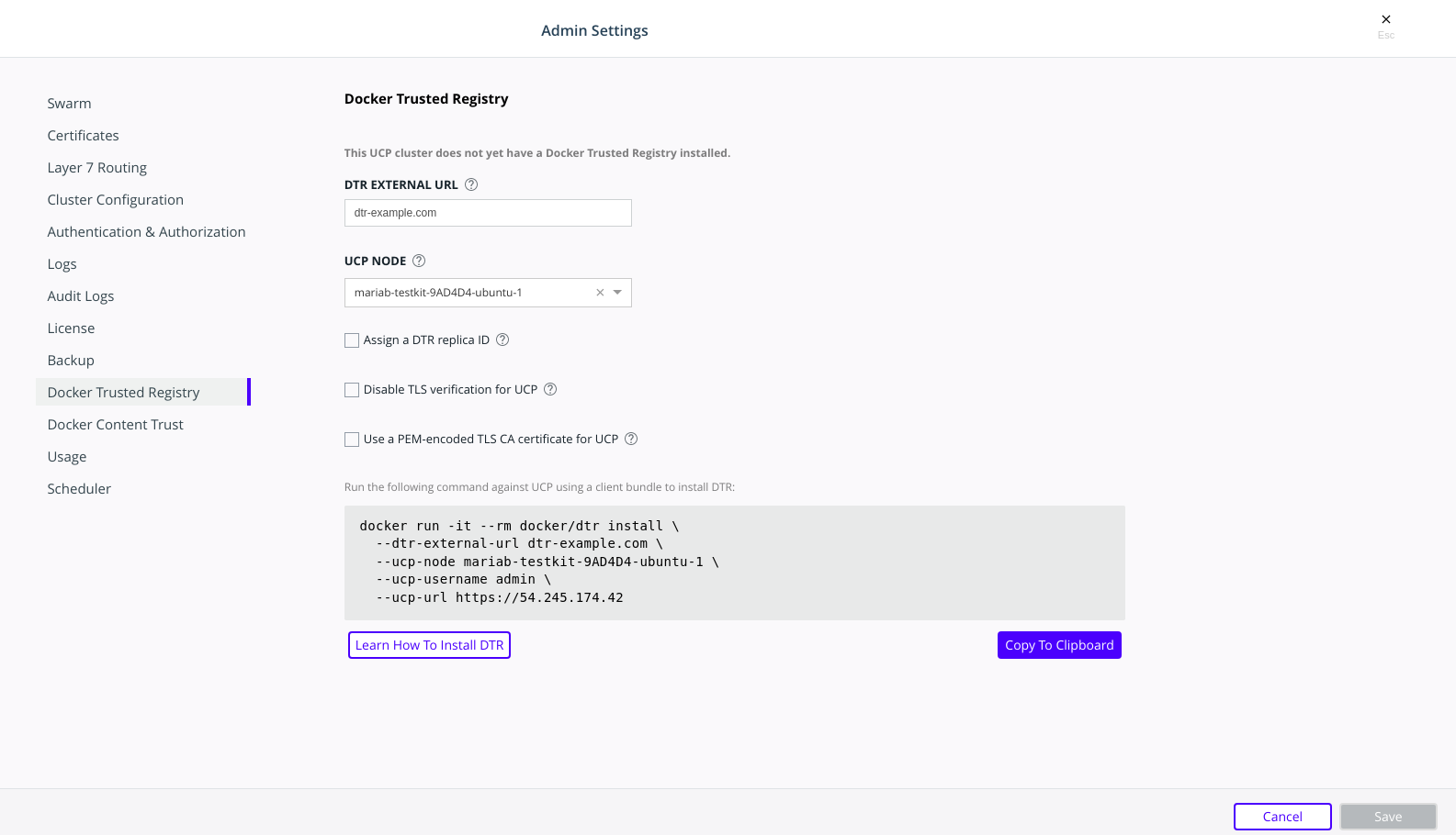
After you configure all the options, you should see a Docker CLI command that you can use to install MSR. Before you run the command, take note of the
--dtr-external-urlparameter:$ docker run -it --rm \ docker/dtr:2.7.5 install \ --dtr-external-url <msr.example.com> \ --ucp-node <mke-node-name> \ --ucp-username admin \ --ucp-url <mke-url>
If you want to point this parameter to a load balancer that uses HTTP for health probes over port
80or443, temporarily reconfigure the load balancer to use TCP over a known open port. Once MSR is installed, you can configure the load balancer however you need to.Run the MSR install command on any node connected to the MKE cluster, and with the Mirantis Container Runtime installed. MSR will not be installed on the node you run the install command on. MSR will be installed on the MKE worker defined by the
--ucp-nodeflag.For example, you could SSH into a MKE node and run the MSR install command from there. Running the installation command in interactive TTY or
-itmode means you will be prompted for any required additional information.Here are some useful options you can set during installation:
- To install a specific version of MSR, replace
2.7.6with your desired version in the installation command above. Find all MSR versions in the Mirantis Secure Registry release notes. - MSR is deployed with self-signed certificates by default, so MKE
might not be able to pull images from MSR. Use the
--dtr-external-url <msr-domain>:<port>optional flag during installation, or during a reconfiguration, so that MKE is automatically reconfigured to trust MSR. - With MSR 2.7, you can enable browser authentication via client certificates at install time. This bypasses the MSR login page and hides the logout button, thereby skipping the need for entering your username and password.
- To install a specific version of MSR, replace
Verify that MSR is installed. Either:
- See
https://<mke-fqdn>/manage/settings/msr, or; - Navigate to Admin Settings > Mirantis Secure Registry from the
MKE web UI. Under the hood, MKE modifies
/etc/docker/certs.dfor each host and adds MSR’s CA certificate. MKE can then pull images from MSR because the Mirantis Container Runtime for each node in the MKE swarm has been configured to trust MSR.
- See
Reconfigure your load balancer back to your desired protocol and port.
Step 4. Check that MSR is running
In your browser, navigate to the MKE web interface.
Select Shared Resources > Stacks from the left navigation pane. You should see MSR listed as a stack.
To verify that MSR is accessible from the browser, enter your MSR IP address or FQDN on the address bar. Since HSTS (HTTP Strict-Transport-Security) header is included in all API responses, make sure to specify the FQDN (Fully Qualified Domain Name) of your MSR prefixed with
https://, or your browser may refuse to load the web interface.
Step 5. Configure MSR
After installing MSR, you should configure:
- The certificates used for TLS communication. Learn more.
- The storage back end to store the Docker images. Learn more.
- To update your TLS certificates, access MSR from the browser and navigate to System > General.
- To configure your storage backend, navigate to System > Storage. If you are upgrading and changing your existing storage back end, see Switch storage back ends for recommended steps.
To reconfigure MSR using the CLI, see the reference page for the reconfigure command.
Step 6. Test pushing and pulling
Now that you have a working installation of MSR, you should test that you can push and pull images:
Step 7. Join replicas to the cluster
This step is optional.
To set up MSR for high availability, you can add more replicas to your MSR cluster. Adding more replicas allows you to load-balance requests across all replicas, and keep MSR working if a replica fails.
For high-availability, you should set 3 or 5 MSR replicas. The replica nodes also need to be managed by the same MKE.
To add replicas to a MSR cluster, use the join command.
Load your MKE user bundle.
Run the join command.
docker run -it --rm \ docker/dtr:2.7.6 join \ --ucp-node <mke-node-name> \ --ucp-insecure-tls
Caution
–ucp-node
The
<mke-node-name>following the--ucp-nodeflag is the target node to install the MSR replica. This is NOT the MKE Manager URL.When you join a replica to a MSR cluster, you need to specify the ID of a replica that is already part of the cluster. You can find an existing replica ID by going to the Shared Resources > Stacks page on MKE.
Check that all replicas are running.
In your browser, navigate to MKE’s web interface. Select Shared Resources > Stacks. All replicas should be displayed.
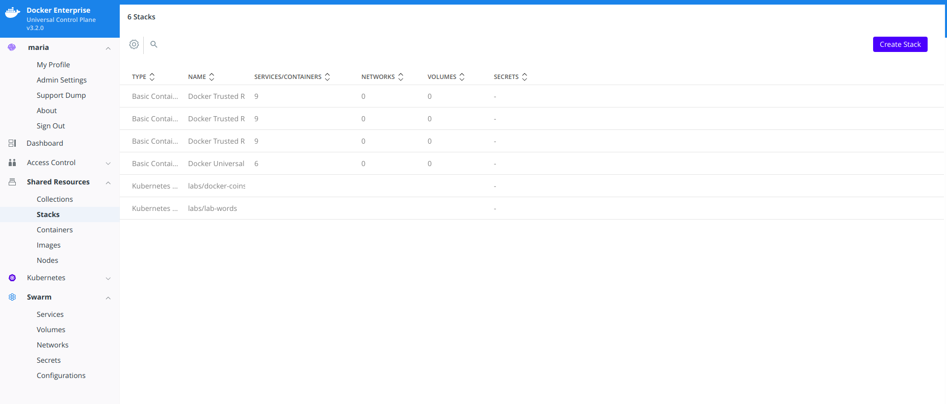
Install MSR offline
The procedure to install Mirantis Secure Registry on a host is the same, whether that host has access to the internet or not.
The only difference when installing on an offline host, is that instead of pulling the MKE images from Docker Hub, you use a computer that is connected to the internet to download a single package with all the images. Then you copy that package to the host where you’ll install MSR.
Versions available
Download the offline package
Use a computer with internet access to download a package with all MSR images:
$ wget <package-url> -O dtr.tar.gz
Now that you have the package in your local machine, you can transfer it to the machines where you want to install MSR.
For each machine where you want to install MSR:
Copy the MSR package to that machine.
$ scp dtr.tar.gz <user>@<host>
Use SSH to log in to the hosts where you transferred the package.
Load the MSR images.
Once the package is transferred to the hosts, you can use the
docker loadcommand to load the Docker images from the tar archive:$ docker load -i dtr.tar.gz
Install MSR
Now that the offline hosts have all the images needed to install MSR, you can install MSR on that host.
MSR makes outgoing connections to:
- Report analytics
- Check for new versions
- Check online licenses
- Update the vulnerability scanning database
All of these uses of online connections are optional. You can choose to disable or not use any or all of these features on the admin settings page.
Upgrade MSR
MSR uses semantic versioning and Docker aims to achieve specific guarantees while upgrading between versions. While downgrades are not supported, Docker supports upgrades according to the following rules:
- When upgrading from one patch version to another, you can skip patch versions because no data migration is performed for patch versions.
- When upgrading between minor versions, you cannot skip versions, however you can upgrade from any patch version of the previous minor version to any patch version of the current minor version.
- When upgrading between major versions, make sure to upgrade one major version at a time – and also to upgrade to the earliest available minor version. It is strongly recommended that you first upgrade to the latest minor/patch version for your major version.
| Description | From | To | Supported |
|---|---|---|---|
| patch upgrade | x.y.0 | x.y.1 | yes |
| skip patch version | x.y.0 | x.y.2 | yes |
| patch downgrade | x.y.2 | x.y.1 | no |
| minor upgrade | x.y.* | x.y+1.* | yes |
| skip minor version | x.y.* | x.y+2.* | no |
| minor downgrade | x.y.* | x.y-1.* | no |
| skip major version | x.. | x+2.. | no |
| major downgrade | x.. | x-1.. | no |
| major upgrade | x.y.z | x+1.0.0 | yes |
| major upgrade skipping minor version | x.y.z | x+1.y+1.z | no |
A few seconds of interruption may occur during the upgrade of a MSR cluster, so schedule the upgrade to take place outside of peak hours to avoid any business impacts.
DTR 2.5 to MSR 2.6 upgrade
Note
Upgrade Best Practices
Important changes have been made to the upgrade process that, if not
correctly followed, can have impact on the availability of applications
running on the Swarm during upgrades. These constraints impact any upgrades
coming from any version before 18.09 to version 18.09 or greater.
In addition, to ensure high availability during the MSR upgrade, drain the MSR replicas and move their workloads to updated workers. This can be done by joining new workers as MSR replicas to your existing cluster and then removing the old replicas. Refer to mirantis/dtr join<:ref:`join command<msr-cli-join> and mirantis/dtr remove for command options and details.
Minor upgrade
Before starting the upgrade, confirm that:
- The version of MKE in use is supported by the upgrade version of MSR. Check the compatibility matrix.
- The MSR backup is recent.
- Docker content trust in MKE is disabled.
- All system requirements are met.
Confirm that you are running MSR 2.6. If this is not the case, upgrade your installation to the 2.6 version.
Pull the latest version of MSR:
docker pull docker/dtr:2.7.6
Confirm that at least 16GB RAM is available on the node on which you are running the upgrade. If the MSR node does not have access to the Internet, follow the Install MSR offline to get the images.
Once you have the latest image on your machine (and the images on the target nodes, if upgrading offline), run the upgrade command.
Note
The upgrade command can be run from any available node, as MKE is aware of which worker nodes have replicas.
docker run -it --rm \
docker/dtr:2.7.6 upgrade
By default, the upgrade command runs in interactive mode and prompts for any
necessary information. You can also check the upgrade reference
page for other existing flags. If you are performing the
upgrade on an existing replica, pass the --existing-replica-id flag.
The upgrade command will start replacing every container in your MSR cluster, one replica at a time. It will also perform certain data migrations. If anything fails or the upgrade is interrupted for any reason, rerun the upgrade command (the upgrade will resume from the point of interruption).
When upgrading from 2.5 to 2.6, the system will run a
metadatastoremigration job following a successful upgrade. This involves
migrating the blob links for your images, which is necessary for online garbage
collection. With 2.6, you can log into the MSR web interface and navigate
to System > Job Logs to check the status of the
metadatastoremigration job. Refer to Audit Jobs via the Web
Interface<msr-manage-jobs-audit-jobs-via-ui> for more details.
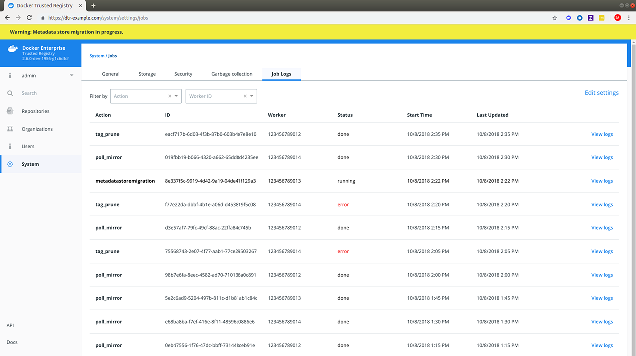
Garbage collection is disabled while the migration is running. In the
case of a failed metadatastoremigration, the system will retry
twice.
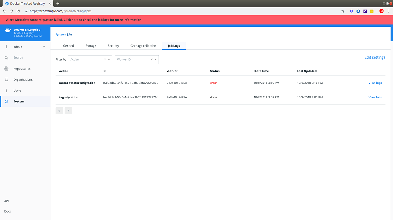
If the three attempts fail, it will be necessary to manually retrigger
the metadatastoremigration job. To do this, send a POST request
to the /api/v0/jobs endpoint:
curl https://<msr-external-url>/api/v0/jobs -X POST \
-u username:accesstoken -H 'Content-Type':'application/json' -d \
'{"action": "metadatastoremigration"}'
Alternatively, select API from the bottom left navigation pane of the MSR web interface and use the Swagger UI to send your API request.
Patch upgrade
A patch upgrade changes only the MSR containers and is always safer than a minor version upgrade. The command is the same as for a minor upgrade.
MSR cache upgrade
If you have previously deployed a cache, be sure to upgrade the node dedicated for your cache to keep it in sync with your upstream MSR replicas. This prevents authentication errors and other strange behaviors.
Download the vulnerability database
After upgrading MSR, it is necessary to redownload the vulnerability database. Learn how to update your vulnerability database.
Uninstall MSR
Uninstalling MSR can be done by simply removing all data associated with each replica. To do that, you just run the destroy command once per replica:
docker run -it --rm \
docker/dtr:2.7.6 destroy \
--ucp-insecure-tls
You will be prompted for the MKE URL, MKE credentials, and which replica to destroy.
To see what options are available in the destroy command, check the destroy command reference documentation.
Configure
License your installation
By default, Mirantis Secure Registry (MSR) automatically uses the same license file applied to your Mirantis Kubernetes Engine (MKE). In the following scenarios, you need to manually apply a license to your MSR:
- Major version upgrade
- License expiration
Download your license
Visit Docker Hub’s Enterprise Trial page to start your one-month trial. After signing up, you should receive a confirmation email with a link to your subscription page. You can find your License Key in the Resources section of the Docker Enterprise Setup Instructions page.
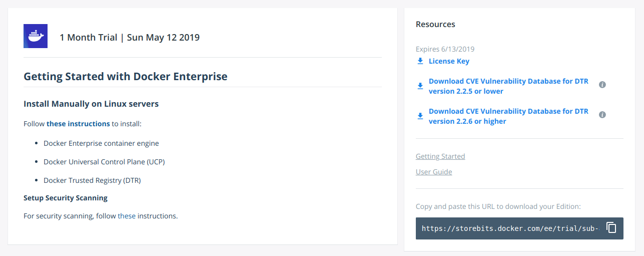
Click “License Key” to download your license.
License your installation
After downloading your license key, navigate to https://<msr-url>
and log in with your credentials. Select System from the left
navigation pane, and click Apply new license to upload your license
key.
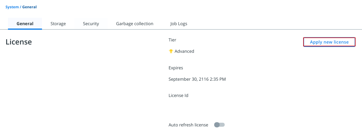
Within System > General under the License section, you should see the tier, date of expiration, and ID for your license.
Where to go next
Use your own TLS certificates
Mirantis Secure Registry (MSR) services are exposed using HTTPS by default. This ensures encrypted communications between clients and your trusted registry. If you do not pass a PEM-encoded TLS certificate during installation, MSR will generate a self-signed certificate. This leads to an insecure site warning when accessing MSR through a browser. Additionally, MSR includes an HSTS (HTTP Strict-Transport-Security) header in all API responses which can further lead to your browser refusing to load MSR’s web interface.
You can configure MSR to use your own TLS certificates, so that it is automatically trusted by your users’ browser and client tools. As of v2.7, you can also enable user authentication via client certificates provided by your organization’s public key infrastructure (PKI).
Replace the server certificates
You can upload your own TLS certificates and keys using the web interface, or pass them as CLI options when installing or reconfiguring your MSR instance.
Navigate to https://<msr-url> and log in with your credentials.
Select System from the left navigation pane, and scroll down to
Domain & Proxies.
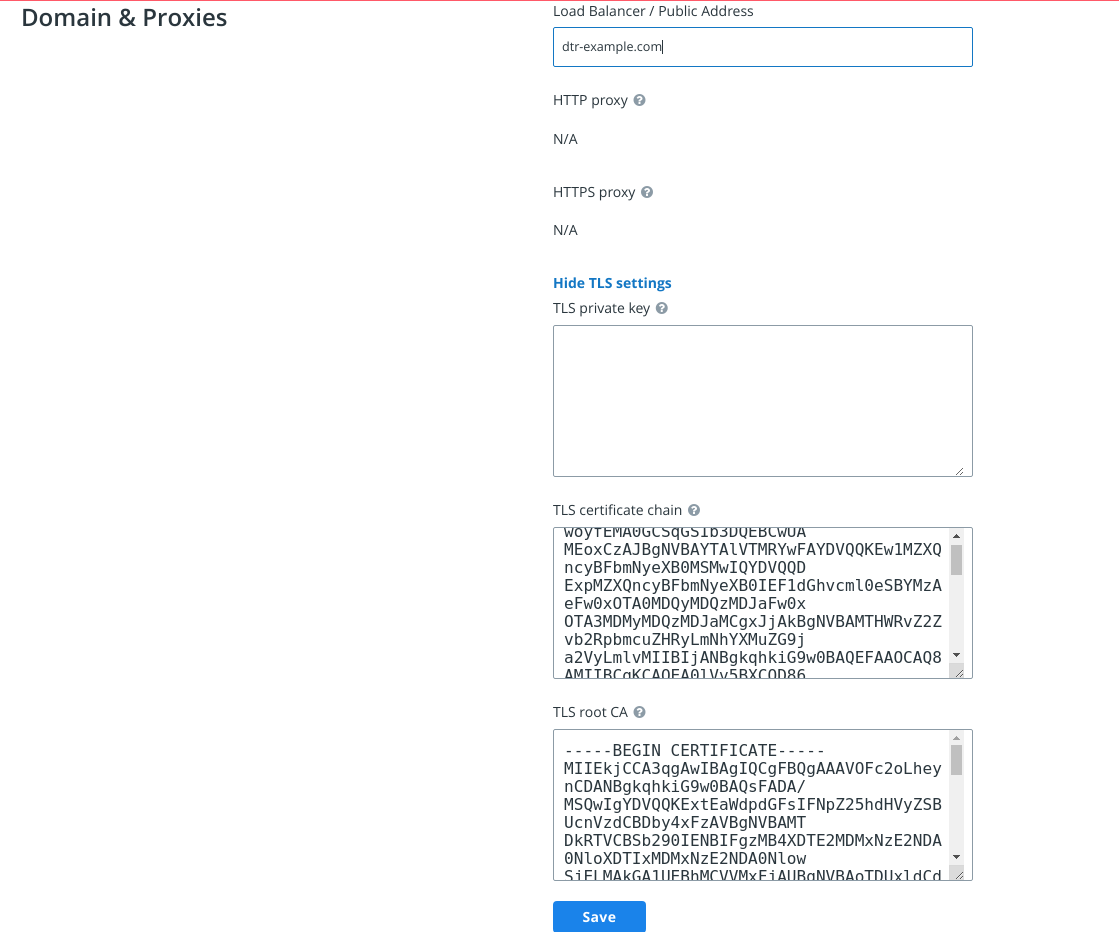
Enter your MSR domain name and upload or copy and paste the certificate details:
- Load balancer/public address. The domain name clients will use to access MSR.
- TLS private key. The server private key.
- TLS certificate chain. The server certificate and any intermediate public certificates from your certificate authority (CA). This certificate needs to be valid for the MSR public address, and have SANs for all addresses used to reach the MSR replicas, including load balancers.
- TLS CA. The root CA public certificate.
Click Save to apply your changes.
If you’ve added certificates issued by a globally trusted CA, any web browser or client tool should now trust MSR. If you’re using an internal CA, you will need to configure the client systems to trust that CA.
See mirantis/dtr install and mirantis/dtr reconfigure for TLS certificate options and usage.
Where to go next
Enable single sign-on
Users are shared between MKE and MSR by default, but the applications have separate browser-based interfaces which require authentication.
To only authenticate once, you can configure MSR to have single sign-on (SSO) with MKE.
Note
After configuring single sign-on with MSR, users accessing
MSR via docker login should create an access
token and use it to authenticate.
At install time
When installing MSR, pass
--dtr-external-url <url> to enable SSO. Specify the Fully Qualified
Domain Name (FQDN) of your MSR, or
a load balancer, to load-balance requests across multiple MSR replicas.
docker run --rm -it \
docker/dtr:2.7.5 install \
--dtr-external-url dtr.example.com \
--dtr-cert "$(cat cert.pem)" \
--dtr-ca "$(cat dtr_ca.pem)" \
--dtr-key "$(cat key.pem)" \
--ucp-url ucp.example.com \
--ucp-username admin \
--ucp-ca "$(cat ucp_ca.pem)"
This makes it so that when you access MSR’s web user interface, you are redirected to the MKE login page for authentication. Upon successfully logging in, you are then redirected to your specified MSR external URL during installation.
Post-installation
Navigate to
https://<msr-url>and log in with your credentials.Select System from the left navigation pane, and scroll down to Domain & Proxies.
Update the Load balancer / Public Address field with the external URL where users should be redirected once they are logged in. Click Save to apply your changes.
Toggle Single Sign-on to automatically redirect users to MKE for logging in.
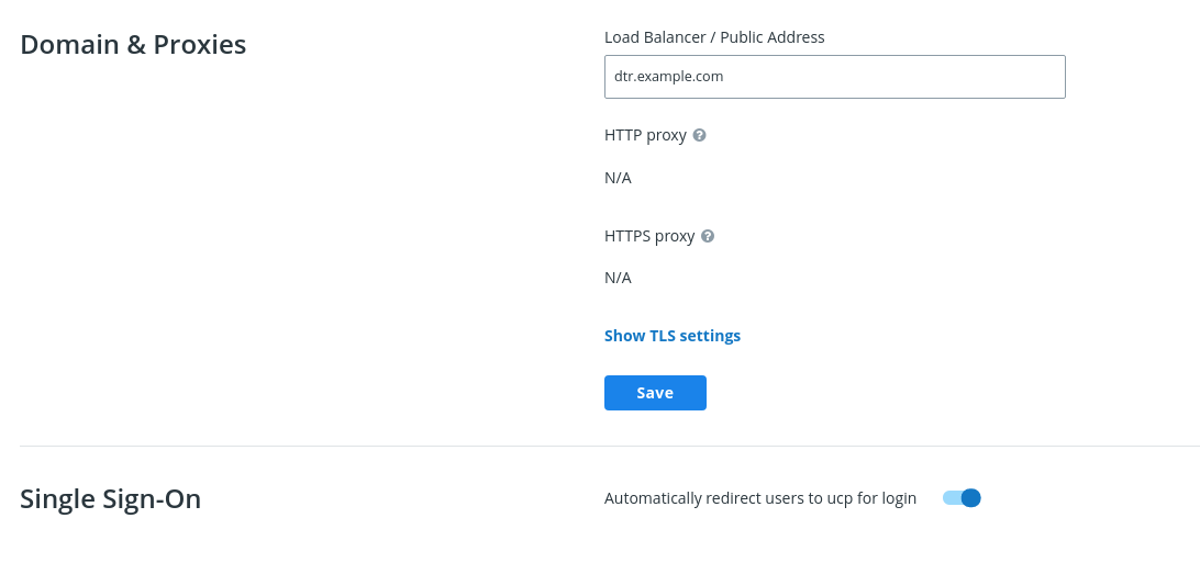
You can also enable single sign-on from the command line by reconfiguring your MSR. To do so, run the following:
docker run --rm -it \
docker/dtr:2.7.5 reconfigure \
--dtr-external-url dtr.example.com \
--dtr-cert "$(cat cert.pem)" \
--dtr-ca "$(cat dtr_ca.pem)" \
--dtr-key "$(cat key.pem)" \
--ucp-url ucp.example.com \
--ucp-username admin \
--ucp-ca "$(cat ucp_ca.pem)"
Where to go next
Disable persistent cookies
If you want your Mirantis Secure Registry (MSR) to use session-based authentication cookies that expire when you close your browser, toggle Disable persistent cookies.
Verify your MSR cookies setting
You may need to disable Single Sign-On (SSO). From the MSR web UI in a Chrome browser, right-click on any page and click Inspect. With the Developer Tools open, select Application > Storage > Cookies > https://<msr-external-url>. Verify that the cookies has Session as the setting for Expires / Max-Age.
Where to go next
External storage
Configure MSR image storage
By default MSR uses the local filesystem of the node where it is running to store your Docker images. You can configure MSR to use an external storage backend, for improved performance or high availability.

If your MSR deployment has a single replica, you can continue using the local filesystem for storing your Docker images. If your MSR deployment has multiple replicas, make sure all replicas are using the same storage backend for high availability. Whenever a user pulls an image, the MSR node serving the request needs to have access to that image.
MSR supports the following storage systems:
- Local filesystem
- NFS
- Bind Mount
- Volume
- Cloud Storage Providers
- Amazon S3
- Microsoft Azure
- OpenStack Swift
- Google Cloud Storage
Note
Some of the previous links are meant to be informative and are not representative of MSR’s implementation of these storage systems.
To configure the storage backend, log in to the MSR web interface as an admin, and navigate to System > Storage.
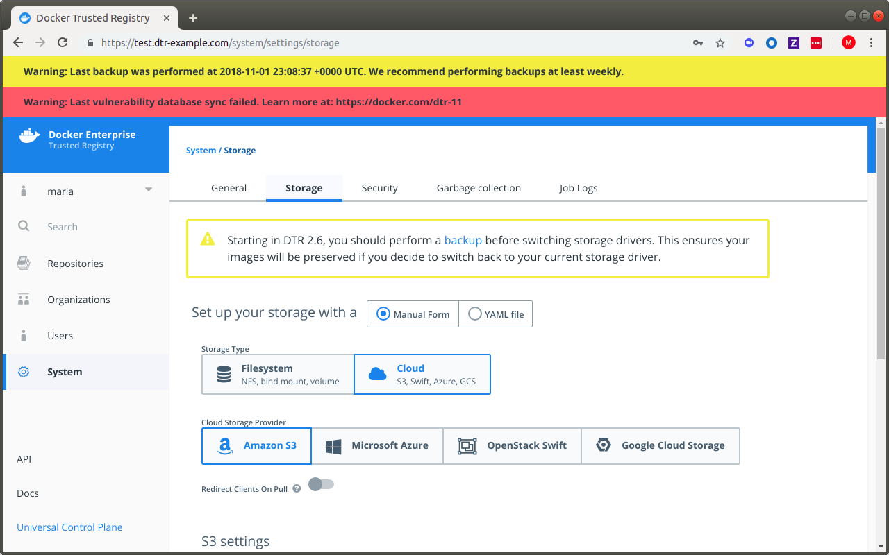
The storage configuration page gives you the most common configuration
options, but you have the option to upload a configuration file in
.yml, .yaml, or .txt format.
By default, MSR creates a volume named dtr-registry-<replica-id> to
store your images using the local filesystem. You can customize the name
and path of the volume by using
mirantis/dtr install --dtr-storage-volume or
mirantis/dtr reconfigure --dtr-storage-volume.
Warning
When running DTR 2.5 (with experimental online garbage collection) and MSR
2.6.0 to 2.6.3, there is an issue with reconfiguring MSR with
--nfs-storage-url which leads to erased tags. Make sure to
back up your MSR metadata before you proceed.
To work around the --nfs-storage-url flag issue, manually create a
storage volume on each MSR node. If MSR is already installed in your
cluster, reconfigure MSR
with the --dtr-storage-volume flag using your newly-created volume.
If you’re deploying MSR with high-availability, you need to use NFS or any other centralized storage backend so that all your MSR replicas have access to the same images.
To check how much space your images are utilizing in the local filesystem, SSH into the MSR node and run:
# Find the path to the volume
docker volume inspect dtr-registry-<replica-id>
# Check the disk usage
sudo du -hs \
$(dirname $(docker volume inspect --format '{{.Mountpoint}}' dtr-registry-<msr-replica>))
{% endraw %}
You can configure your MSR replicas to store images on an NFS partition, so that all replicas can share the same storage backend.
MSR supports Amazon S3 or other storage systems that are S3-compatible like Minio. Learn how to configure MSR with Amazon S3.
Switching storage backends
Starting in MSR 2.6, switching storage backends initializes a new
metadata store and erases your existing tags. This helps facilitate
online garbage collection, which has been introduced in 2.5 as an
experimental feature. In earlier versions, MSR would subsequently start
a tagmigration job to rebuild tag metadata from the file layout in
the image layer store. This job has been discontinued for DTR 2.5.x
(with garbage collection) and MSR 2.6, as your storage backend could get
out of sync with your MSR metadata, like your manifests and existing
repositories. As best practice, MSR storage backends and metadata should
always be moved, backed up, and restored together.
In MSR 2.6.4, a new flag, --storage-migrated, has been added to
mirantis/dtr reconfigure which lets you indicate
the migration status of your storage data during a reconfigure. If you are not
worried about losing your existing tags, you can skip the recommended steps
below and perform a reconfigure.
Docker recommends the following steps for your storage backend and metadata migration:
Disable garbage collection by selecting “Never” under System > Garbage Collection, so blobs referenced in the backup that you create continue to exist. See Garbage collection for more details. Make sure to keep it disabled while you’re performing the metadata backup and migrating your storage data.

Back up your existing metadata. See mirantis/dtr backup for CLI command description and options.
Migrate the contents of your current storage backend to the new one you are switching to. For example, upload your current storage data to your new NFS server.
Restore MSR from your backup and specify your new storage backend. See mirantis/dtr destroy and mirantis/dtr restore for CLI command descriptions and options.
With MSR restored from your backup and your storage data migrated to your new backend, garbage collect any dangling blobs using the following API request:
curl -u <username>:$TOKEN -X POST "https://<msr-url>/api/v0/jobs" -H "accept: application/json" -H "content-type: application/json" -d "{ \"action": \"onlinegc_blobs\" }"
On success, you should get a
202 Acceptedresponse with a jobidand other related details. This ensures any blobs which are not referenced in your previously created backup get destroyed.
If you have a long maintenance window, you can skip some steps from above and do the following:
Put MSR in “read-only” mode using the following API request:
curl -u <username>:$TOKEN -X POST "https://<msr-url>/api/v0/meta/settings" -H "accept: application/json" -H "content-type: application/json" -d "{ \"readOnlyRegistry\": true }"
On success, you should get a
202 Acceptedresponse.Migrate the contents of your current storage backend to the new one you are switching to. For example, upload your current storage data to your new NFS server.
Reconfigure MSR while specifying the
--storage-migratedflag to preserve your existing tags.
Make sure to perform a backup before you change your storage backend when running DTR 2.5 (with online garbage collection) and MSR 2.6.0-2.6.3. If you encounter an issue with lost tags, refer to the following resources:
- For changes to reconfigure and restore options in MSR 2.6, see mirantis/dtr reconfigure and mirantis/dtr restore.
- For Docker’s recommended recovery strategies, see MSR 2.6 lost tags after reconfiguring storage.
- For NFS-specific changes, refer to Configuring MSR for NFS.
- For S3-specific changes, refer to Configuring MSR for S3.
Upgrade to MSR 2.6.4 and follow best practice for data migration to avoid the wiped tags issue when moving from one NFS server to another.
Configuring MSR for S3
You can configure MSR to store Docker images on Amazon S3, or other file servers with an S3-compatible API like Cleversafe or Minio.
Amazon S3 and compatible services store files in “buckets”, and users have permissions to read, write, and delete files from those buckets. When you integrate MSR with Amazon S3, MSR sends all read and write operations to the S3 bucket so that the images are persisted there.
Before configuring MSR you need to create a bucket on Amazon S3. To get faster pulls and pushes, you should create the S3 bucket on a region that’s physically close to the servers where MSR is running.
Start by creating a bucket. Then, as a best practice you should create a new IAM user just for the MSR integration and apply an IAM policy that ensures the user has limited permissions.
This user only needs permissions to access the bucket that you’ll use to store images, and be able to read, write, and delete files.
Here’s an example of a user policy:
{
"Version": "2012-10-17",
"Statement": [
{
"Effect": "Allow",
"Action": "s3:ListAllMyBuckets",
"Resource": "arn:aws:s3:::*"
},
{
"Effect": "Allow",
"Action": [
"s3:ListBucket",
"s3:GetBucketLocation",
"s3:ListBucketMultipartUploads"
],
"Resource": "arn:aws:s3:::<bucket-name>"
},
{
"Effect": "Allow",
"Action": [
"s3:PutObject",
"s3:GetObject",
"s3:DeleteObject",
"s3:ListBucketMultipartUploads"
],
"Resource": "arn:aws:s3:::<bucket-name>/*"
}
]
}
Once you’ve created a bucket and user, you can configure MSR to use it.
In your browser, navigate to https://<msr-url. Select System >
Storage.
Select the S3 option, and fill-in the information about the bucket and user.
| Field | Description |
|---|---|
| Root directory | The path in the bucket where images are stored. |
| AWS Region name | The region where the bucket is. Learn more |
| S3 bucket name | The name of the bucket to store the images. |
| AWS access key | The access key to use to access the S3 bucket. This can be left empty if you’re using an IAM policy. Learn more |
| AWS secret key | The secret key to use to access the S3 bucket. This can be left empty if you’re using an IAM policy. |
| Region endpoint | The endpoint name for the region you’re using. Learn more |
There are also some advanced settings.
| Field | Description |
|---|---|
| Signature version 4 auth | Authenticate the requests using AWS signature version 4. Learn more |
| Use HTTPS | Secure all requests with HTTPS, or make requests in an insecure way |
| Skip TLS verification | Encrypt all traffic, but don’t verify the TLS certificate used by the storage backend. |
| Root CA certificate | The public key certificate of the root certificate authority that issued the storage backend certificate. |
Once you click Save, MSR validates the configurations and saves the changes.
If you’re using a TLS certificate in your storage backend that’s not globally trusted, you’ll have to configure all Docker Engines that push or pull from MSR to trust that certificate. When you push or pull an image MSR redirects the requests to the storage backend, so if clients don’t trust the TLS certificates of both MSR and the storage backend, they won’t be able to push or pull images. Learn how to configure the Docker client.
And if you’ve configured MSR to skip TLS verification, you also need to configure all Docker Engines that push or pull from MSR to skip TLS verification. You do this by adding MSR to the list of insecure registries when starting Docker.
MSR supports the following S3 regions:
| Region |
|---|
| us-east-1 |
| us-east-2 |
| us-west-1 |
| us-west-2 |
| eu-west-1 |
| eu-west-2 |
| eu-central-1 |
| ap-south-1 |
| ap-southeast-1 |
| ap-southeast-2 |
| ap-northeast-1 |
| ap-northeast-2 |
| sa-east-1 |
| cn-north-1 |
| us-gov-west-1 |
| ca-central-1 |
When running DTR 2.5.x (with experimental garbage collection) or MSR 2.6.0-2.6.4, there is an issue with changing your S3 settings on the web interface which leads to erased metadata. Make sure to back up your MSR metadata before you proceed.
To restore MSR using your previously configured S3
settings,
use mirantis/dtr restore with --dtr-use-default-storage to keep
your metadata.
Configuring MSR for NFS
You can configure MSR to store Docker images in an NFS directory. Starting in MSR 2.6, changing storage backends involves initializing a new metadatastore instead of reusing an existing volume. This helps facilitate online garbage collection. See changes to NFS reconfiguration below if you have previously configured MSR to use NFS.
Before installing or configuring MSR to use an NFS directory, make sure that:
- The NFS server has been correctly configured
- The NFS server has a fixed IP address
- All hosts running MSR have the correct NFS libraries installed
To confirm that the hosts can connect to the NFS server, try to list the directories exported by your NFS server:
showmount -e <nfsserver>
You should also try to mount one of the exported directories:
mkdir /tmp/mydir && sudo mount -t nfs <nfs server>:<directory> /tmp/mydir
One way to configure MSR to use an NFS directory is at install time:
docker run -it --rm docker/dtr:2.7.5 install \
--nfs-storage-url <nfs-storage-url> \
<other options>
Use the format nfs://<nfs server>/<directory> for the NFS storage
URL. To support NFS v4, you can now specify additional options when
running mirantis/dtr install with
--nfs-storage-url.
When joining replicas to a MSR cluster, the replicas will pick up your storage configuration, so you will not need to specify it again.
To support NFS v4, more NFS options have been added to the CLI.
Warning
When running DTR 2.5 (with experimental online garbage collection) andMSR
2.6.0 to 2.6.3, there is an issue with reconfiguring and restoring MSR
with --nfs-storage-url which leads to erased tags. Make sure to
back up your MSR metadata before you proceed.
To work around the --nfs-storage-url flag issue, manually create a
storage volume. If MSR is already installed in your cluster, reconfigure
MSR<msr-cli-reconfigure> with the --dtr-storage-volume flag using your
newly-created volume.
See Reconfigure Using a Local NFS Volume for Docker’s recommended recovery strategy.
In MSR 2.6.4, a new flag, --storage-migrated has been added to
mirantis/dtr reconfigure which lets you indicate the
migration status of your storage data during a reconfigure. Upgrade to
2.6.4 and follow Best practice for data migration
in 2.6.4 when switching storage backends.
The following shows you how to reconfigure MSR using an NFSv4 volume as a
storage backend:
docker run --rm -it \
docker/dtr:2.7.5 reconfigure \
--ucp-url <mke_url> \
--ucp-username <mke_username> \
--nfs-storage-url <msr-registry-nf>
--async-nfs
--storage-migrated
To reconfigure DTR to stop using NFS storage, leave the
--nfs-storage-url option blank:
docker run -it --rm docker/dtr:2.7.5 reconfigure \
--nfs-storage-url ""
Set up high availability
Mirantis Secure Registry is designed to scale horizontally as your usage increases. You can add more replicas to make MSR scale to your demand and for high availability.
All MSR replicas run the same set of services and changes to their configuration are automatically propagated to other replicas.

To make MSR tolerant to failures, add additional replicas to the MSR cluster.
| MSR replicas | Failures tolerated |
|---|---|
| 1 | 0 |
| 3 | 1 |
| 5 | 2 |
| 7 | 3 |
When sizing your MSR installation for high-availability, follow these rules of thumb:
- Don’t create a MSR cluster with just two replicas. Your cluster won’t tolerate any failures, and it’s possible that you experience performance degradation.
- When a replica fails, the number of failures tolerated by your cluster decreases. Don’t leave that replica offline for long.
- Adding too many replicas to the cluster might also lead to performance degradation, as data needs to be replicated across all replicas.
To have high-availability on MKE and MSR, you need a minimum of:
- 3 dedicated nodes to install MKE with high availability,
- 3 dedicated nodes to install MSR with high availability,
- As many nodes as you want for running your containers and applications.
You also need to configure the MSR replicas to share the same object storage.
Join more MSR replicas
To add replicas to an existing MSR deployment:
Use ssh to log into any node that is already part of MKE.
Run the MSR join command:
docker run -it --rm \ docker/dtr:2.7.5 join \ --ucp-node <mke-node-name> \ --ucp-insecure-tls
Where the
--ucp-nodeis the hostname of the MKE node where you want to deploy the MSR replica.--ucp-insecure-tlstells the command to trust the certificates used by MKE.If you have a load balancer, add this MSR replica to the load balancing pool.
Remove existing replicas
To remove a MSR replica from your deployment:
Use ssh to log into any node that is part of MKE.
Run the MSR remove command:
docker run -it --rm \ docker/dtr:2.7.5 remove \ --ucp-insecure-tls
You will be prompted for:
- Existing replica id: the id of any healthy MSR replica of that cluster
- Replica id: the id of the MSR replica you want to remove. It can be the id of an unhealthy replica
- MKE username and password: the administrator credentials for MKE
If you’re load-balancing user requests across multiple MSR replicas, don’t forget to remove this replica from the load balancing pool.
Where to go next
Use a load balancer
Once you’ve joined multiple MSR replicas nodes for high-availability, you can configure your own load balancer to balance user requests across all replicas.

This allows users to access MSR using a centralized domain name. If a replica goes down, the load balancer can detect that and stop forwarding requests to it, so that the failure goes unnoticed by users.
MSR exposes several endpoints you can use to assess if a MSR replica is healthy or not:
/_ping: Is an unauthenticated endpoint that checks if the MSR replica is healthy. This is useful for load balancing or other automated health check tasks./nginx_status: Returns the number of connections being handled by the NGINX front-end used by MSR./api/v0/meta/cluster_status: Returns extensive information about all MSR replicas.
Load balance MSR
MSR does not provide a load balancing service. You can use an on-premises or cloud-based load balancer to balance requests across multiple MSR replicas.
Important
Additional load balancer requirements for MKE
If you are also using MKE, there are additional requirements if you plan to load balance both MKE and MSR using the same load balancer.
You can use the unauthenticated /_ping endpoint on each MSR replica,
to check if the replica is healthy and if it should remain in the load
balancing pool or not.
Also, make sure you configure your load balancer to:
- Load balance TCP traffic on ports 80 and 443.
- Not terminate HTTPS connections.
- Not buffer requests.
- Forward the
HostHTTP header correctly. - Have no timeout for idle connections, or set it to more than 10 minutes.
The /_ping endpoint returns a JSON object for the replica being
queried of the form:
{
"Error": "error message",
"Healthy": true
}
A response of "Healthy": true means the replica is suitable for
taking requests. It is also sufficient to check whether the HTTP status
code is 200.
An unhealthy replica will return 503 as the status code and populate
"Error" with more details on any one of these services:
- Storage container (registry)
- Authorization (garant)
- Metadata persistence (rethinkdb)
- Content trust (notary)
Note that this endpoint is for checking the health of a single replica. To get the health of every replica in a cluster, querying each replica individually is the preferred way to do it in real time.
Configuration examples
Use the following examples to configure your load balancer for MSR.
You can deploy your load balancer using:
Where to go next
Set up security scanning in MSR
This page explains how to set up and enable Docker Security Scanning on an existing installation of Mirantis Secure Registry.
Prerequisites
These instructions assume that you have already installed Mirantis Secure Registry, and have access to an account on the MSR instance with administrator access.
Before you begin, make sure that you or your organization has purchased a MSR license that includes Docker Security Scanning, and that your Docker ID can access and download this license from the Docker Hub.
If you are using a license associated with an individual account, no
additional action is needed. If you are using a license associated with
an organization account, you may need to make sure your Docker ID is a
member of the Owners team. Only Owners team members can download
license files for an Organization.
If you will be allowing the Security Scanning database to update itself
automatically, make sure that the server hosting your MSR instance can
access https://dss-cve-updates.docker.com/ on the standard https
port 443.
Get the security scanning license
If your MSR instance already has a license that includes Security Scanning, skip this section and proceed to ** Enable MSR security scanning**.
Tip
To check if your existing MSR license includes scanning, navigate to the MSR Settings page, and click Security. If an “Enable scanning” toggle appears, the license includes scanning.
If your current MSR license doesn’t include scanning, you must first download the new license.
Log in to the Docker Hub using a Docker ID with access to the license you need.
In the top right corner, click your user account icon, and select My Content.
Locate Docker Enterprise Edition in the content list, and click Setup.
Click License Key to download the license.

Next, install the new license on the MSR instance.
Log in to your MSR instance using an administrator account.
Click Settings in the left navigation.
On the General tab click Apply new license.
A file browser dialog displays.
Navigate to where you saved the license key (
.lic) file, select it, and click Open.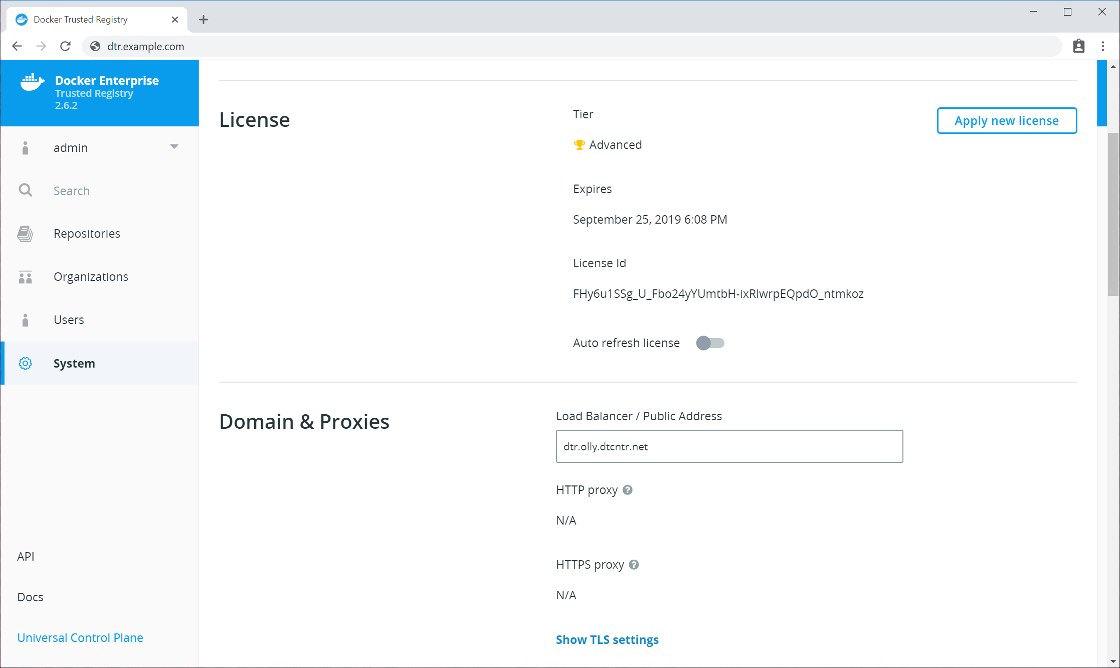
Enable MSR security scanning
To enable security scanning in MSR:
Log in to your MSR instance with an administrator account.
Click Settings in the left navigation.
Click the Security tab.
Click the Enable scanning toggle so that it turns blue and says “on”.
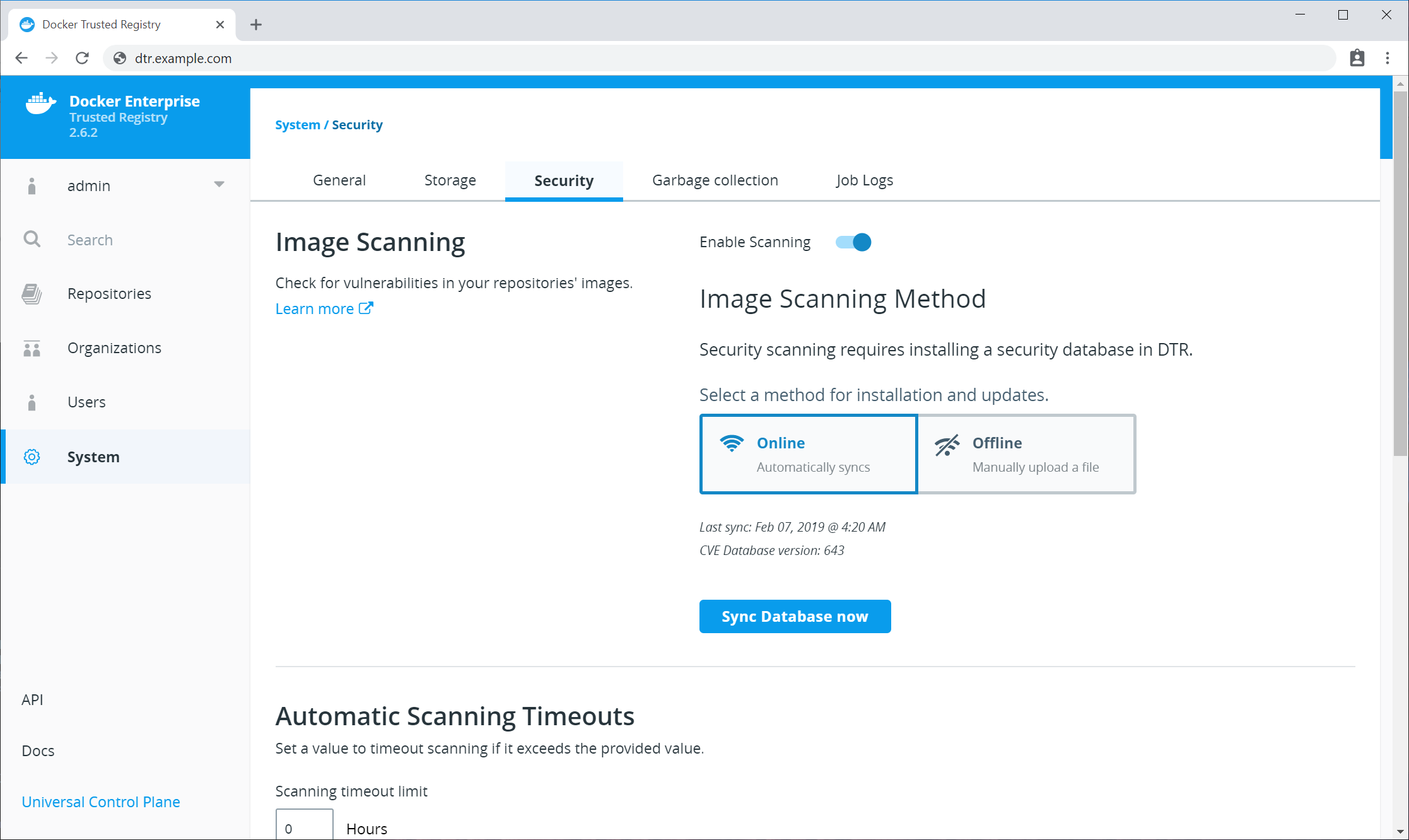
Next, provide a security database for the scanner. Security scanning will not function until MSR has a security database to use.
By default, security scanning is enabled in Online mode. In this mode, MSR attempts to download a security database from a Docker server. If your installation cannot access
https://dss-cve-updates.docker.com/you must manually upload a.tarfile containing the security database.- If you are using
Onlinemode, the MSR instance will contact a Docker server, download the latest vulnerability database, and install it. Scanning can begin once this process completes. - If you are using
Offlinemode, use the instructions in Update scanning database - offline mode to upload an initial security database.
- If you are using
By default when Security Scanning is enabled, new repositories will
automatically scan on docker push. If you had existing repositories
before you enabled security scanning, you might want to change
repository scanning behavior.
Set repository scanning mode
Two modes are available when Security Scanning is enabled:
Scan on push & Scan manually: the image is re-scanned on eachdocker pushto the repository, and whenever a user withwriteaccess clicks the Start Scan links or Scan button.Scan manually: the image is scanned only when a user withwriteaccess clicks the Start Scan links or Scan button.
By default, new repositories are set to Scan on push & Scan manually, but
you can change this setting during repository creation.
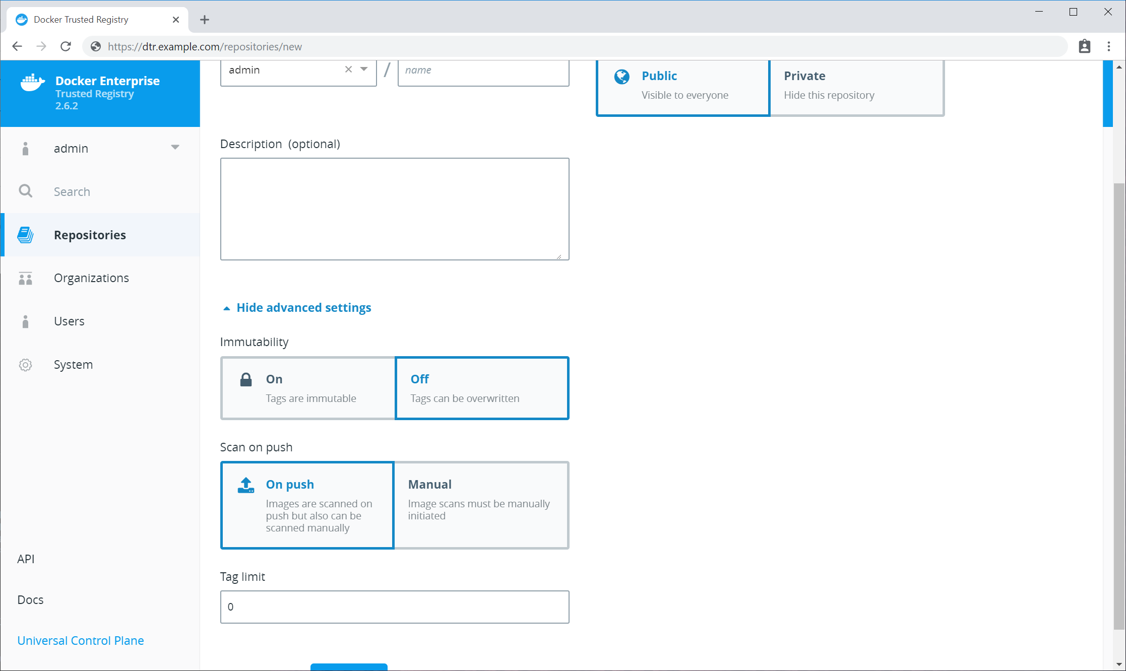
Any repositories that existed before scanning was enabled are set to
Scan manually mode by default. If these repositories are still in
use, you can change this setting from each repository’s Settings
page.
Note
To change an individual repository’s scanning mode, you must have write or admin access to the repo.
To change an individual repository’s scanning mode:
Navigate to the repository, and click the Settings tab.
Scroll down to the Image scanning section.
Select the desired scanning mode.
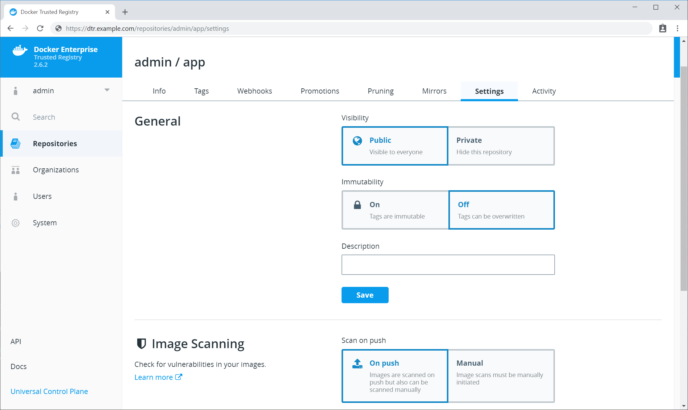
Update the CVE scanning database
Docker Security Scanning indexes the components in your MSR images and compares them against a known CVE database. When new vulnerabilities are reported, Docker Security Scanning matches the components in new CVE reports to the indexed components in your images, and quickly generates an updated report.
Users with administrator access to MSR can check when the CVE database was last updated from the Security tab in the MSR Settings pages.
By default Docker Security Scanning checks automatically for updates to the vulnerability database, and downloads them when available. If your installation does not have access to the public internet, use the Offline mode instructions below.
To ensure that MSR can access these updates, make sure that the host can
reach https://dss-cve-updates.docker.com/ on port 443 using https.
MSR checks for new CVE database updates at 3:00 AM UTC every day. If an update is found it is downloaded and applied without interrupting any scans in progress. Once the update is complete, the security scanning system looks for new vulnerabilities in the indexed components.
To set the update mode to Online:
- Log in to MSR as a user with administrator rights.
- Click Settings in the left navigation and click Security.
- Click Online.
Your choice is saved automatically.
Tip
MSR also checks for CVE database updates when scanning is first enabled, and when you switch update modes. If you need to check for a CVE database update immediately, you can briefly switch modes from online to offline and back again.
To update the CVE database for your MSR instance when it cannot contact
the update server, you download and install a .tar file that
contains the database updates. To download the file:
Log in to Docker Hub.
If you are a member of an Organization managing licenses using Docker Hub, make sure your account is a member of the
Ownersteam. Only Owners can view and manage licenses and other entitlements for Organizations from Docker Hub.In the top right corner, click your user account icon, and select My Content.
If necessary, select an organization account from the Accounts menu at the upper right.
Locate your Docker EE Advanced subscription or trial.
Click Setup button.
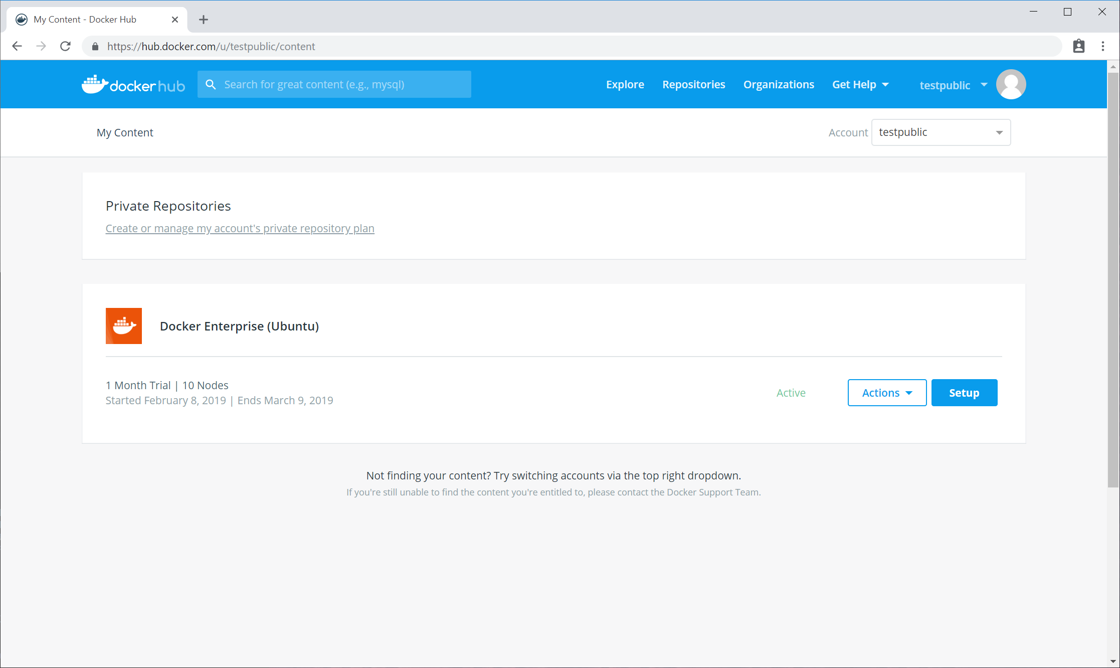
Click Download CVE Vulnerability Database link to download the database file.
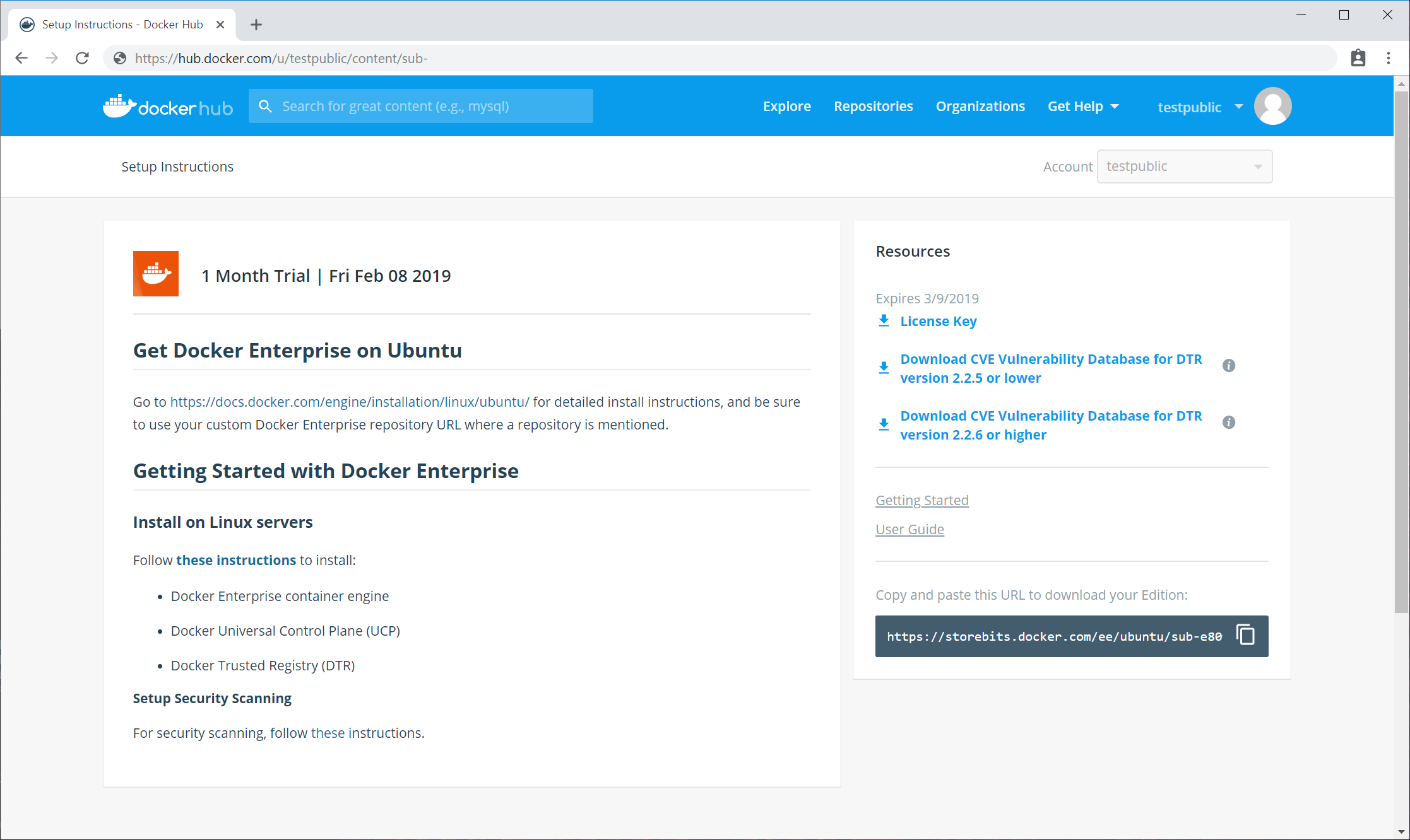
To manually update the MSR CVE database from a .tar file:
- Log in to MSR as a user with administrator rights.
- Click Settings in the left navigation and click Security.
- Click Upload .tar database file.
- Browse to the latest
.tarfile that you received, and click Open.
MSR installs the new CVE database, and begins checking already indexed images for components that match new or updated vulnerabilities.
Tip
The Upload button is unavailable while MSR applies CVE database updates.
Enable or disable automatic database updates
To change the update mode:
- Log in to MSR as a user with administrator rights.
- Click Settings in the left navigation and click Security.
- Click Online/Offline.
Your choice is saved automatically.
Deploy caches
MSR cache fundamentals
The further away you are from the geographical location where MSR is deployed, the longer it will take to pull and push images. This happens because the files being transferred from MSR to your machine need to travel a longer distance, across multiple networks.

To decrease the time to pull an image, you can deploy MSR caches geographically closer to users.
Caches are transparent to users, since users still log in and pull images using the MSR URL address. MSR checks if users are authorized to pull the image, and redirects the request to the cache.

In this example, MSR is deployed on a datacenter in the United States, and a cache is deployed in the Asia office.
Users in the Asia office update their user profile within MSR to fetch from the cache in their office. They pull an image using:
# Log in to DTR
docker login dtr.example.org
# Pull image
docker image pull dtr.example.org/website/ui:3-stable
MSR authenticates the request and checks if the user has permission to pull the image they are requesting. If they have permissions, they get an image manifest containing the list of image layers to pull and redirecting them to pull the images from the Asia cache.
When users request those image layers from the Asia cache, the cache pulls them from MSR and keeps a copy that can be used to serve to other users without having to pull the image layers from MSR again.
Use caches if you:
- Want to make image pulls faster for users in different geographical regions.
- Want to manage user permissions from a central place.
If you need users to be able to push images faster, or you want to implement RBAC policies based on different regions, do not use caches. Instead, deploy multiple MSR clusters and implement mirroring policies between them.

With mirroring policies you can set up a development pipeline where images are automatically pushed between different MSR repositories, or across MSR deployments.
As an example you can set up a development pipeline with three different stages. Developers can push and pull images from the development environment, only pull from QA, and have no access to Production.
With multiple MSR deployments you can control the permissions developers have for each deployment, and you can create policies to automatically push images from one deployment to the next. Learn more about deployment policies.
Cache deployment strategy
The main reason to use a MSR cache is so that users can pull images from a service that’s geographically closer to them.
In this example a company has developers spread across three locations: United States, Asia, and Europe. Developers working in the US office can pull their images from MSR without problem, but developers in the Asia and Europe offices complain that it takes them a long time to pulls images.

To address that, you can deploy MSR caches in the Asia and Europe offices, so that developers working from there can pull images much faster.
To deploy the MSR caches for this scenario, you need three datacenters:
- The US datacenter runs MSR configured for high availability.
- The Asia datacenter runs a MSR cache.
- The Europe datacenter runs another MSR cache.

Both caches are configured to fetch images from MSR.
Before deploying a MSR cache in a datacenter, make sure you:
- Provision multiple nodes and install Docker on them.
- Join the nodes into a Swarm.
- Have one or more dedicated worker nodes just for running the MSR cache.
- Have TLS certificates to use for securing the cache.
- Have a shared storage system, if you want the cache to be highly available.
If you only plan on running a MSR cache on this datacenter, you just need Docker EE Basic, which only includes the Docker Engine.
If you plan on running other workloads on this datacenter, consider deploying Docker EE Standard or Advanced. This way you can enforce fine-grain control over cluster resources, and makes it easier to monitor and manage your applications.
You can customize the port used by the MSR cache, so you’ll have to configure your firewall rules to make sure users can access the cache using the port you chose.
By default the documentation guides you in deploying caches that are exposed on port 443/TCP using the swarm routing mesh.
Deploy a MSR cache with Swarm
This example guides you in deploying a MSR cache, assuming that you’ve got a MSR deployment up and running. It also assumes that you’ve provisioned multiple nodes and joined them into a swarm.

Cache for Asia
The MSR cache is going to be deployed as a Docker service, so that Docker automatically takes care of scheduling and restarting the service if something goes wrong.
We’ll manage the cache configuration using a Docker configuration, and the TLS certificates using Docker secrets. This allows you to manage the configurations securely and independently of the node where the cache is actually running.
To make sure the MSR cache is performant, it should be deployed on a node dedicated just for it. Start by labelling the node where you want to deploy the cache, so that you target the deployment to that node.
Use SSH to log in to a manager node of the swarm where you want to deploy the MSR cache. If you’re using MKE to manage that swarm, use a client bundle to configure your Docker CLI client to connect to the swarm.
docker node update --label-add dtr.cache=true <node-hostname>
Create a file structure that looks like this:
├── docker-stack.yml # Stack file to deploy cache with a single command
├── config.yml # The cache configuration file
└── certs
├── cache.cert.pem # The cache public key certificate
├── cache.key.pem # The cache private key
└── dtr.cert.pem # DTR CA certificate
Then add the following content to each of the files:
With this configuration, the cache fetches image layers from MSR and keeps a local copy for 24 hours. After that, if a user requests that image layer, the cache fetches it again from MSR.
The cache is configured to persist data inside its container. If something goes wrong with the cache service, Docker automatically redeploys a new container, but previously cached data is not persisted. You can customize the storage parameters, if you want to store the image layers using a persistent storage backend.
Also, the cache is configured to use port 443. If you’re already using that port in the swarm, update the deployment and configuration files to use another port. Don’t forget to create firewall rules for the port you choose.
Now that everything is set up, you can deploy the cache by running:
docker stack deploy --compose-file docker-stack.yml dtr-cache
You can check if the cache has been successfully deployed by running:
docker stack ps dtr-cache
Docker should show the dtr-cache stack is running.
Now that you’ve deployed a cache, you need to configure MSR to know
about it. This is done using the POST /api/v0/content_caches API.
You can use the MSR interactive API documentation to use this API.
In the MSR web UI, click the top-right menu, and choose API docs.
Navigate to the POST /api/v0/content_caches line and click it to
expand. In the body field include:
{
"name": "region-asia",
"host": "https://<cache-url>:<cache-port>"
}
Click the Try it out! button to make the API call.
Now that you’ve registered the cache with MSR, users can configure their user profile to pull images from MSR or the cache.
In the MSR web UI, navigate to your Account, click the Settings tab, and change the Content Cache settings to use the cache you deployed.

If you need to set this for multiple users at the same time, use the
/api/v0/accounts/{username}/settings API endpoint.
Now when you pull images, you’ll be using the cache.
To validate that the cache is working as expected:
- Push an image to MSR.
- Make sure your user account is configured to use the cache.
- Delete the image from your local system.
- Pull the image from MSR.
To validate that the cache is actually serving your request, and to troubleshoot misconfigurations, check the logs for the cache service by running:
docker service logs --follow dtr-cache_cache
The most common causes of configuration are due to TLS authentication:
- MSR not trusting the cache TLS certificates.
- The cache not trusting MSR TLS certificates.
- Your machine not trusting MSR or the cache.
When this happens, check the cache logs to troubleshoot the misconfiguration.
The certificates and private keys are now managed by Docker in a secure way. Don’t forget to delete sensitive files you’ve created on disk, like the private keys for the cache:
rm -rf certs
Deploy a MSR cache with Kubernetes
This example guides you through deploying a MSR cache, assuming that you’ve got a MSR deployment up and running. The below guide has been tested on Mirantis Kubernetes Engine 3.1, however it should work on any Kubernetes Cluster 1.8 or higher.
The MSR cache is going to be deployed as a Kubernetes Deployment, so that Kubernetes automatically takes care of scheduling and restarting the service if something goes wrong.
We’ll manage the cache configuration using a Kubernetes Config Map, and the TLS certificates using Kubernetes secrets. This allows you to manage the configurations securely and independently of the node where the cache is actually running.
At the end of this exercise you should have the following file structure on your workstation:
├── dtrcache.yaml # Yaml file to deploy cache with a single command
├── config.yaml # The cache configuration file
└── certs
├── cache.cert.pem # The cache public key certificate, including any intermediaries
├── cache.key.pem # The cache private key
└── dtr.cert.pem # DTR CA certificate
The MSR cache will be deployed with a TLS endpoint. For this you will need to generate a TLS ceritificate and key from a certificate authority. The way you expose the MSR Cache will change the SANs required for this certificate.
For example:
- If you are deploying the MSR Cache with an Ingress Object you will need to use an external MSR cache address which resolves to your ingress controller as part of your certificate.
- If you are exposing the MSR cache through a Kubernetes Cloud Provider then you will need the external Loadbalancer address as part of your certificate.
- If you are exposing the MSR Cache through a Node Port or a Host Port you will need to use a node’s FQDN as a SAN in your certificate.
On your workstation, create a directory called certs. Within it
place the newly created certificate cache.cert.pem and key
cache.key.pem for your MSR cache. Also place the certificate
authority (including any intermedite certificate authorities) of the
certificate from your MSR deployment. This could be sourced from the
main MSR deployment using curl.
$ curl -s https://<msr-fqdn>/ca -o certs/dtr.cert.pem`.
The MSR Cache will take its configuration from a file mounted into the container. Below is an example configuration file for the MSR Cache. This yaml should be customised for your environment with the relevant external msr cache, worker node or external loadbalancer FQDN.
With this configuration, the cache fetches image layers from MSR and keeps a local copy for 24 hours. After that, if a user requests that image layer, the cache will fetch it again from MSR.
The cache, by default, is configured to store image data inside its container. Therefore if something goes wrong with the cache service, and Kubernetes deploys a new pod, cached data is not persisted. Data will not be lost as it is still stored in the primary MSR. You can customize the storage parameters, if you want the cached images to be backended by persistent storage.
Note
Kubernetes Peristent Volumes or Persistent Volume Claims would have to be used to provide persistent backend storage capabilities for the cache.
cat > config.yaml <<EOF
version: 0.1
log:
level: info
storage:
delete:
enabled: true
filesystem:
rootdirectory: /var/lib/registry
http:
addr: 0.0.0.0:443
secret: generate-random-secret
host: https://<external-fqdn-msrcache> # Could be DTR Cache / Loadbalancer / Worker Node external FQDN
tls:
certificate: /certs/cache.cert.pem
key: /certs/cache.key.pem
middleware:
registry:
- name: downstream
options:
blobttl: 24h
upstreams:
- https://<msr-url> # URL of the Main DTR Deployment
cas:
- /certs/dtr.cert.pem
EOF
The Kubernetes Manifest file to deploy the MSR Cache is independent of how you choose to expose the MSR cache within your environment. The below example has been tested to work on Mirantis Kubernetes Engine 3.1, however it should work on any Kubernetes Cluster 1.8 or higher.
cat > dtrcache.yaml <<EOF
apiVersion: apps/v1beta2
kind: Deployment
metadata:
name: dtr-cache
namespace: dtr
spec:
replicas: 1
selector:
matchLabels:
app: dtr-cache
template:
metadata:
labels:
app: dtr-cache
annotations:
seccomp.security.alpha.kubernetes.io/pod: docker/default
spec:
containers:
- name: dtr-cache
image: docker/dtr-content-cache:2.7.5
command: ["bin/sh"]
args:
- start.sh
- /config/config.yaml
ports:
- name: https
containerPort: 443
volumeMounts:
- name: dtr-certs
readOnly: true
mountPath: /certs/
- name: dtr-cache-config
readOnly: true
mountPath: /config
volumes:
- name: dtr-certs
secret:
secretName: dtr-certs
- name: dtr-cache-config
configMap:
defaultMode: 0666
name: dtr-cache-config
EOF
At this point you should have a file structure on your workstation which looks like this:
├── dtrcache.yaml # Yaml file to deploy cache with a single command
├── config.yaml # The cache configuration file
└── certs
├── cache.cert.pem # The cache public key certificate
├── cache.key.pem # The cache private key
└── dtr.cert.pem # DTR CA certificate
You will also need the kubectl command line tool configured to talk
to your Kubernetes cluster, either through a Kubernetes Config file or a
Mirantis Kubernetes Engine client bundle.
First we will create a Kubernetes namespace to logically separate all of our MSR cache components.
$ kubectl create namespace dtr
Create the Kubernetes Secrets, containing the MSR cache TLS certificates, and a Kubernetes ConfigMap containing the MSR cache configuration file.
$ kubectl -n dtr create secret generic dtr-certs \
--from-file=certs/dtr.cert.pem \
--from-file=certs/cache.cert.pem \
--from-file=certs/cache.key.pem
$ kubectl -n dtr create configmap dtr-cache-config \
--from-file=config.yaml
Finally create the Kubernetes Deployment.
$ kubectl create -f dtrcache.yaml
You can check if the deployment has been successful by checking the
running pods in your cluster: kubectl -n dtr get pods
If you need to troubleshoot your deployment, you can use
kubectl -n dtr describe pods <pods> and / or
kubectl -n dtr logs <pods>.
For external access to the MSR cache we need to expose the Cache Pods to the outside world. In Kubernetes there are multiple ways for you to expose a service, dependent on your infrastructure and your environment. For more information, see Publishing services - service types on the Kubernetes docs. It is important though that you are consistent in exposing the cache through the same interface you created a certificate for previously. Otherwise the TLS certificate may not be valid through this alternative interface.
MSR Cache Exposure
You only need to expose your MSR cache through one external interface.
The first example exposes the MSR cache through NodePort. In this example you would have added a worker node’s FQDN to the TLS Certificate in step 1. Here you will be accessing the MSR cache through an exposed port on a worker node’s FQDN.
cat > dtrcacheservice.yaml <<EOF
apiVersion: v1
kind: Service
metadata:
name: dtr-cache
namespace: dtr
spec:
type: NodePort
ports:
- name: https
port: 443
targetPort: 443
protocol: TCP
selector:
app: dtr-cache
EOF
kubectl create -f dtrcacheservice.yaml
To find out which port the MSR cache has been exposed on, you will need to run:
$ kubectl -n dtr get services
You can test that your MSR cache is externally reachable by using
curl to hit the API endpoint, using both a worker node’s external
address, and the NodePort.
curl -X GET https://<workernodefqdn>:<nodeport>/v2/_catalog
{"repositories":[]}
This second example will expose the MSR cache through an ingress object. In this example you will need to create a DNS rule in your environment that will resolve a MSR cache external FQDN address to the address of your ingress controller. You should have also specified the same MSR cache external FQDN address within the MSR cache certificate in step 1.
Note
An ingress controller is a prerequisite for this example. If you have not deployed an ingress controller on your cluster, see Layer 7 Routing for MKE. This ingress controller will also need to support SSL passthrough.
cat > dtrcacheservice.yaml <<EOF
kind: Service
apiVersion: v1
metadata:
name: dtr-cache
namespace: dtr
spec:
selector:
app: dtr-cache
ports:
- protocol: TCP
port: 443
targetPort: 443
---
apiVersion: extensions/v1beta1
kind: Ingress
metadata:
name: dtr-cache
namespace: dtr
annotations:
nginx.ingress.kubernetes.io/ssl-passthrough: "true"
nginx.ingress.kubernetes.io/secure-backends: "true"
spec:
tls:
- hosts:
- <external-msr-cache-fqdn> # Replace this value with your external DTR Cache address
rules:
- host: <external-msr-cache-fqdn> # Replace this value with your external DTR Cache address
http:
paths:
- backend:
serviceName: dtr-cache
servicePort: 443
EOF
kubectl create -f dtrcacheservice.yaml
You can test that your MSR cache is externally reachable by using curl to hit the API endpoint. The address should be the one you have defined above in the serivce definition file.
curl -X GET https://external-dtr-cache-fqdn/v2/_catalog
{"repositories":[]}
Configure caches for high availability
If you’re deploying a MSR cache in a zone with few users and with no uptime SLAs, a single cache service is enough for you.
But if you want to make sure your MSR cache is always available to users and is highly performant, you should configure your cache deployment for high availability.

- Multiple nodes, one for each cache replica.
- A load balancer.
- Shared storage system that has read-after-write consistency.
The way you deploy a MSR cache is the same, whether you’re deploying a single replica or multiple ones. The difference is that you should configure the replicas to store data using a shared storage system.
When using a shared storage system, once an image layer is cached, any replica is able to serve it to users without having to fetch a new copy from MSR.
MSR caches support the following storage systems: * Alibaba Cloud Object Storage Service * Amazon S3 * Azure Blob Storage * Google Cloud Storage * NFS * Openstack Swift
If you’re using NFS as a shared storage system, make sure the shared directory is configured with:
/dtr-cache *(rw,root_squash,no_wdelay)
This ensures read-after-write consistency for NFS.
You should also mount the NFS directory on each node where you’ll deploy a MSR cache replica.
Use SSH to log in to a manager node of the swarm where you want to deploy the MSR cache.
If you’re using MKE to manage that swarm you can also use a client bundle to configure your Docker CLI client to connect to that swarm.
Label each node that is going to run the cache replica, by running:
docker node update --label-add dtr.cache=true <node-hostname>
Create the cache configuration files by following the instructions for deploying a single cache replica.
Make sure you adapt the storage object, using the configuration
options for the shared storage of your choice.
The last step is to deploy a load balancer of your choice to load-balance requests across the multiple replicas you deployed.
MSR cache configuration reference
MSR caches are based on Docker Registry, and use the same configuration file format.
The MSR cache extends the Docker Registry configuration file format by
introducing a new middleware called downstream that has three
configuration options: blobttl, upstreams, and cas:
# Settings that you would include in a
# Docker Registry configuration file followed by
middleware:
registry:
- name: downstream
options:
blobttl: 24h
upstreams:
- <Externally-reachable address for upstream registry or content cache in format scheme://host:port>
cas:
- <Absolute path to next-hop upstream registry or content cache CA certificate in the container's filesystem>
Below you can find the description for each parameter, specific to MSR caches.
| Parameter | Required | Description |
|---|---|---|
blobttl |
No | A positive integer and an optional unit of time suffix to determine the
TTL (Time to Live) value for blobs in the cache. If blobttl is
configured, storage.delete.enabled must be set to true.
Acceptable units of time are:
- ns (nanoseconds)
- us (microseconds)
- ms (milliseconds)
- s (seconds)
- m (minutes)
- h (hours)
If you omit the suffix, the system interprets the value as nanoseconds. |
cas |
No | An optional list of absolute paths to PEM-encoded CA certificates of upstream registries or content caches. |
upstreams |
Yes | A list of externally-reachable addresses for upstream registries of content caches. If more than one host is specified, it will pull from registries in round-robin order. |
Garbage collection
You can configure the Mirantis Secure Registry (MSR) to automatically delete unused image layers, thus saving you disk space. This process is also known as garbage collection.
How MSR deletes unused layers
First you configure MSR to run a garbage collection job on a fixed schedule. At the scheduled time, MSR:
- Identifies and marks unused image layers.
- Deletes the marked image layers.
MSR uses online garbage collection. This allows MSR to run garbage collection without setting MSR to read-only/offline mode. In previous versions, garbage collection would set MSR to read-only/offline mode so MSR would reject pushes. Online garbage collection was an experimental feature in v2.5.
Schedule garbage collection
In your browser, navigate to https://<msr-url> and log in with your
credentials. Select System on the left navigation pane, and then
click the Garbage collection tab to schedule garbage collection.
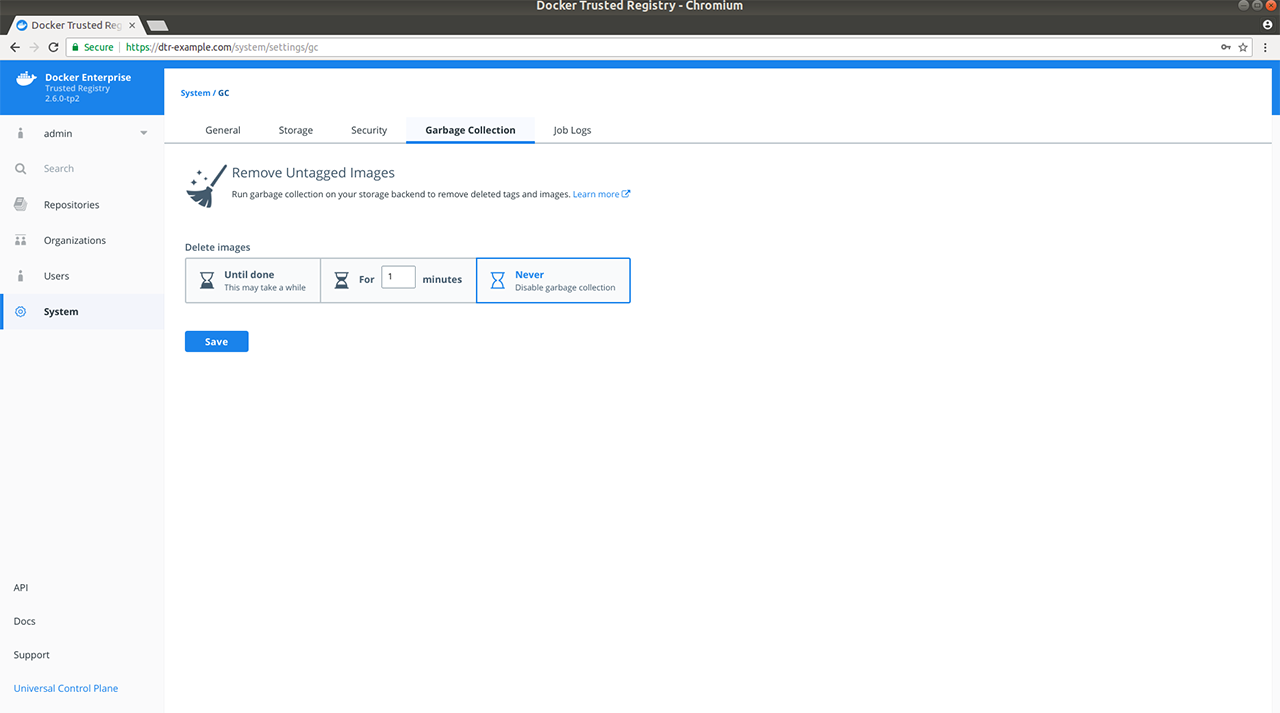
Select for how long the garbage collection job should run:
- Until done: Run the job until all unused image layers are deleted.
- For x minutes: Only run the garbage collection job for a maximum of x minutes at a time.
- Never: Never delete unused image layers.
If you select Until done or For x minutes, you can specify a recurring schedule in UTC (Coordinated Universal Time) with the following options:
- Custom cron schedule - (Hour, Day of Month, Month, Weekday)
- Daily at midnight UTC
- Every Saturday at 1am UTC
- Every Sunday at 1am UTC
- Do not repeat
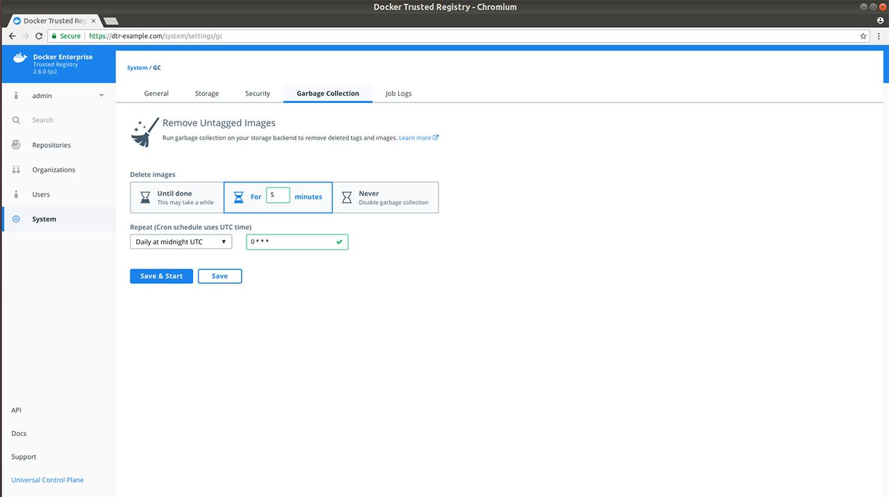
Once everything is configured you can choose to Save & Start to run the garbage collection job immediately, or just Save to run the job on the next scheduled interval.
Review the garbage collection job log
In v2.5, you were notified with a banner under main navigation that no one can push images while a garbage collection job is running. With v2.6, this is no longer the case since garbage collection now happens while MSR is online and writable.
If you clicked Save & Start previously, verify that the garbage collection routine started by navigating to Job Logs.
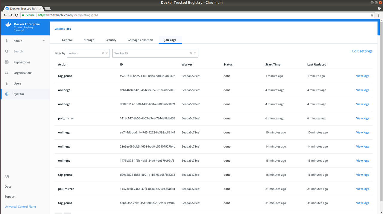
Under the hood
Each image stored in MSR is made up of multiple files:
- A list of image layers that are unioned which represents the image filesystem
- A configuration file that contains the architecture of the image and other metadata
- A manifest file containing the list of all layers and configuration file for an image
All these files are tracked in MSR’s metadata store in RethinkDB. These files are tracked in a content-addressable way such that a file corresponds to a cryptographic hash of the file’s content. This means that if two image tags hold exactly the same content, MSR only stores the image content once while making hash collisions nearly impossible, even if the tag name is different.
As an example, if wordpress:4.8 and wordpress:latest have the
same content, the content will only be stored once. If you delete one of
these tags, the other won’t be deleted.
This means that when you delete an image tag, MSR cannot delete the underlying files of that image tag since other tags may also use the same files.
To facilitate online garbage collection, MSR makes a couple of changes to how it uses the storage backend:
- Layer links – the references within repository directories to their associated blobs – are no longer in the storage backend. That is because MSR stores these references in RethinkDB instead to enumerate through them during the marking phase of garbage collection.
- Any layers created after an upgrade to 2.6 are no longer content-addressed in the storage backend. Many cloud provider backends do not give the sequential consistency guarantees required to deal with the simultaneous deleting and re-pushing of a layer in a predictable manner. To account for this, MSR assigns each newly pushed layer a unique ID and performs the translation from content hash to ID in RethinkDB.
To delete unused files, MSR does the following:
- Establish a cutoff time.
- Mark each referenced manifest file with a timestamp. When manifest files are pushed to MSR, they are also marked with a timestamp.
- Sweep each manifest file that does not have a timestamp after the cutoff time.
- If a file is never referenced – which means no image tag uses it – delete the file.
- Repeat the process for blob links and blob descriptors.
Where to go next
Allow users to create repositories when pushing
By default MSR only allows pushing images if the repository exists, and you have write access to the repository.
As an example, if you try to push to msr.example.org/library/java:9,
and the library/java repository doesn’t exist yet, your push fails.
You can configure MSR to allow pushing to repositories that don’t exist yet. As an administrator, log into the MSR web UI, navigate to the Settings page, and enable Create repository on push.
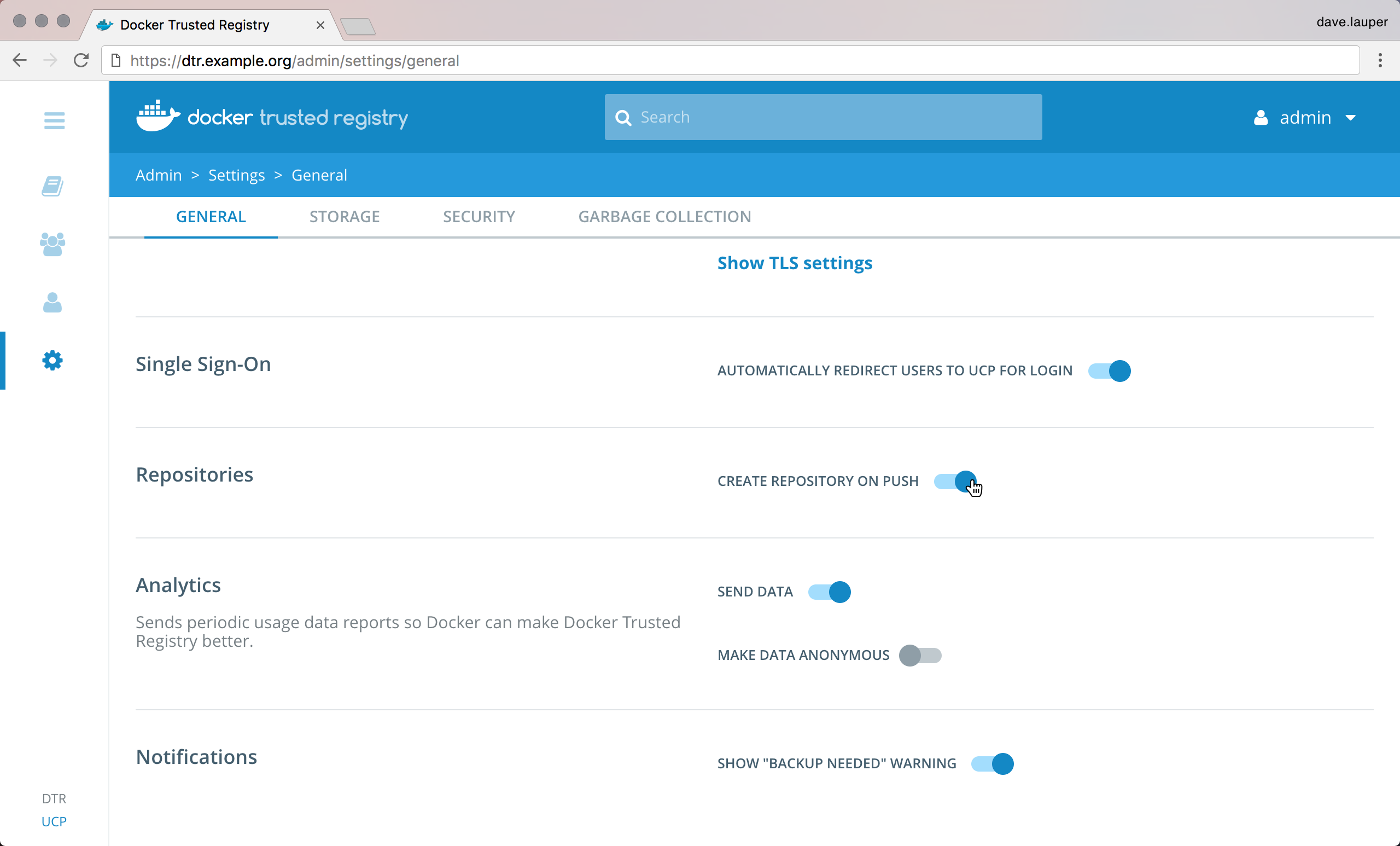
From now on, when a user pushes to their personal sandbox
(<user-name>/<repository>), or if the user is an administrator for
the organization (<org>/<repository>), MSR will create a repository
if it doesn’t exist yet. In that case, the repository is created as
private.
Use the CLI to enable pushing to repositories that don’t exist yet
curl --user <admin-user>:<password> \
--request POST "<msr-url>/api/v0/meta/settings" \
--header "accept: application/json" \
--header "content-type: application/json" \
--data "{ \"createRepositoryOnPush\": true}"
Use a web proxy
Mirantis Secure Registry makes outgoing connections to check for new versions, automatically renew its license, and update its vulnerability database. If MSR can’t access the internet, then you’ll have to manually apply updates.
One option to keep your environment secure while still allowing MSR access to the internet is to use a web proxy. If you have an HTTP or HTTPS proxy, you can configure MSR to use it. To avoid downtime you should do this configuration outside business peak hours.
As an administrator, log into a node where MSR is deployed, and run:
docker run -it --rm \
docker/dtr:2.7.5 reconfigure \
--http-proxy http://<domain>:<port> \
--https-proxy https://<doman>:<port> \
--ucp-insecure-tls
To confirm how MSR is configured, check the Settings page on the web UI.
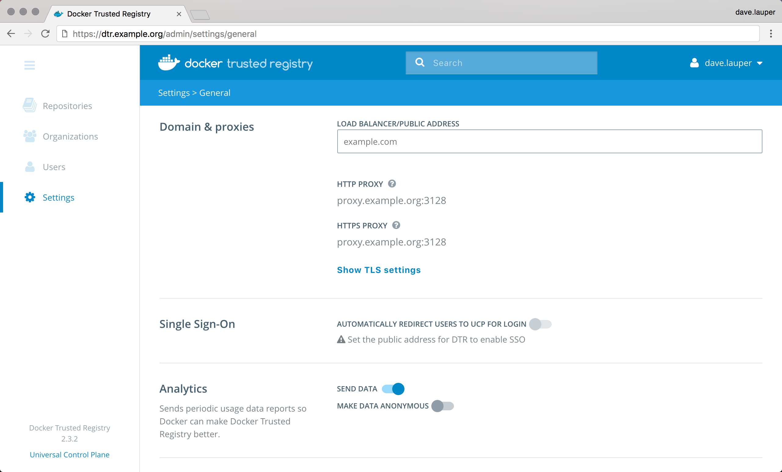
If by chance the web proxy requires authentication you can submit the username and password, in the command, as shown below:
docker run -it --rm \
docker/dtr:2.7.5 reconfigure \
--http-proxy username:password@<domain>:<port> \
--https-proxy username:password@<doman>:<port> \
--ucp-insecure-tls
Note
MSR will hide the password portion of the URL, when it is displayed in the MSR UI.
Where to go next
Manage users
Authentication and authorization in MSR
With MSR you get to control which users have access to your image repositories.
By default, anonymous users can only pull images from public repositories. They can’t create new repositories or push to existing ones. You can then grant permissions to enforce fine-grained access control to image repositories. For that:
Start by creating a user.
Users are shared across MKE and MSR. When you create a new user in Mirantis Kubernetes Engine, that user becomes available in MSR and vice versa. Registered users can create and manage their own repositories.
You can also integrate with an LDAP service to manage users from a single place.
Extend the permissions by adding the user to a team.
To extend a user’s permission and manage their permissions over repositories, you add the user to a team. A team defines the permissions users have for a set of repositories.
Organizations and teams
When a user creates a repository, only that user can make changes to the repository settings, and push new images to it.
Organizations take permission management one step further, since they allow multiple users to own and manage a common set of repositories. This is useful when implementing team workflows. With organizations you can delegate the management of a set of repositories and user permissions to the organization administrators.
An organization owns a set of repositories, and defines a set of teams. With teams you can define fine-grain permissions that a team of user has for a set of repositories.

In this example, the ‘Whale’ organization has three repositories and two teams:
- Members of the blog team can only see and pull images from the whale/java repository,
- Members of the billing team can manage the whale/golang repository, and push and pull images from the whale/java repository.
Where to go next
Create and manage users
When using the built-in authentication, you can create users to grant them fine-grained permissions.
Users are shared across MKE and MSR. When you create a new user in Mirantis Kubernetes Engine, that user becomes available in MSR and vice versa.
To create a new user, go to the MSR web UI, and navigate to the Users page.
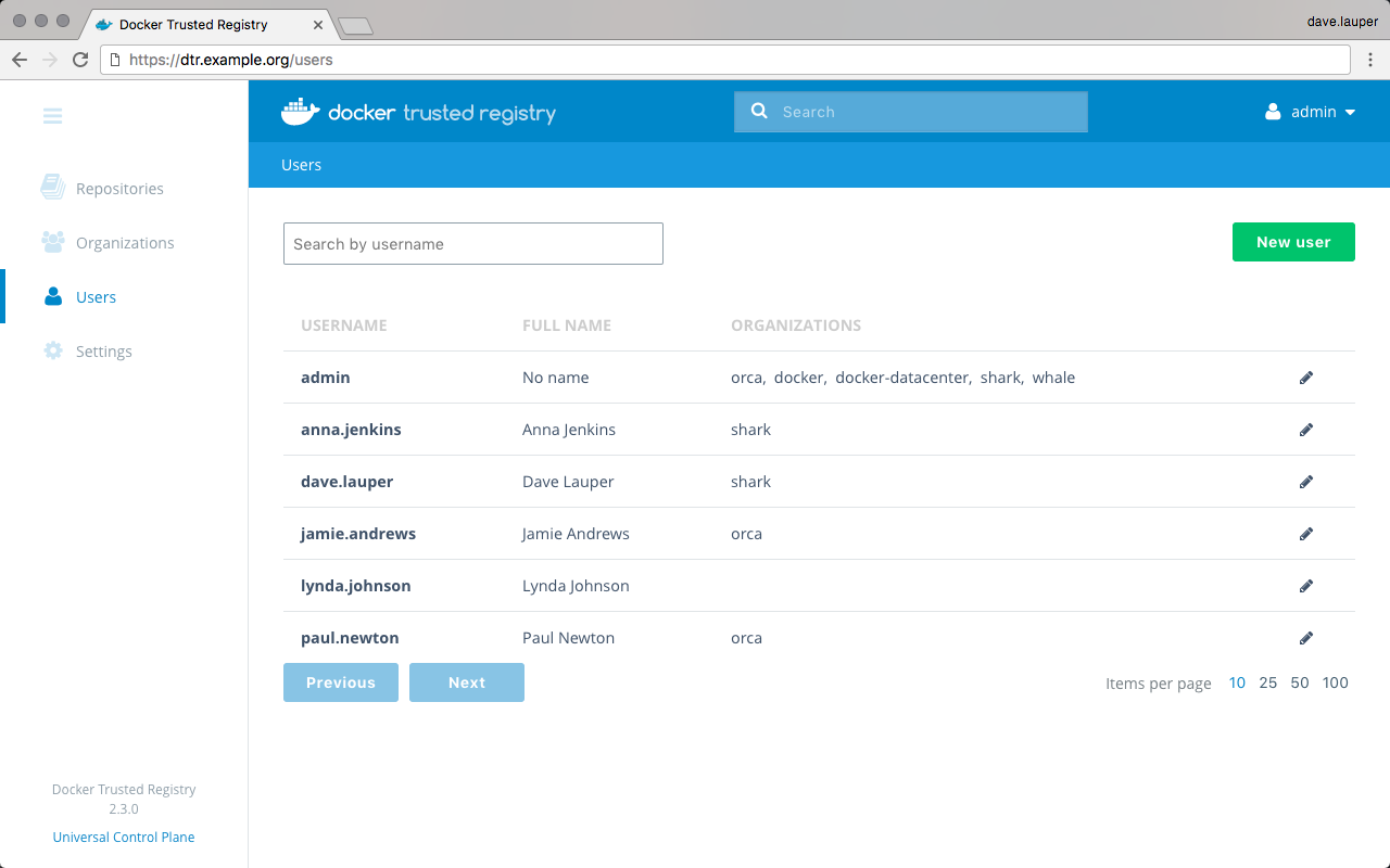
Click the New user button, and fill-in the user information.

Check the Trusted Registry admin option, if you want to grant permissions for the user to be a MKE and MSR administrator.
Where to go next
Create and manage teams
You can extend a user’s default permissions by granting them individual permissions in other image repositories, by adding the user to a team. A team defines the permissions a set of users have for a set of repositories.
To create a new team, go to the MSR web UI, and navigate to the Organizations page. Then click the organization where you want to create the team. In this example, we’ll create the ‘billing’ team under the ‘whale’ organization.
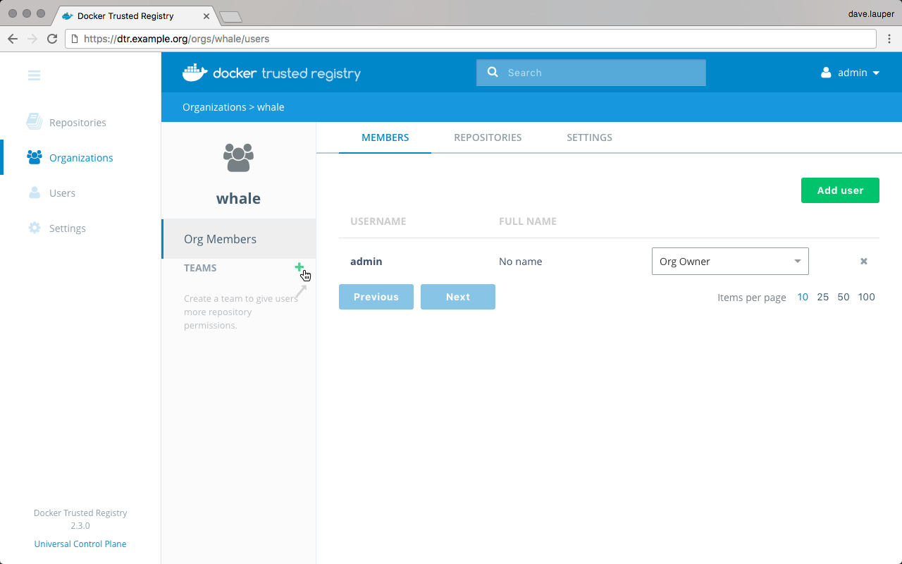
Click ‘+’ to create a new team, and give it a name.
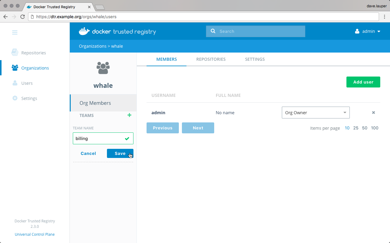
Add users to a team
Once you have created a team, click the team name, to manage its settings. The first thing we need to do is add users to the team. Click the Add user button and add users to the team.
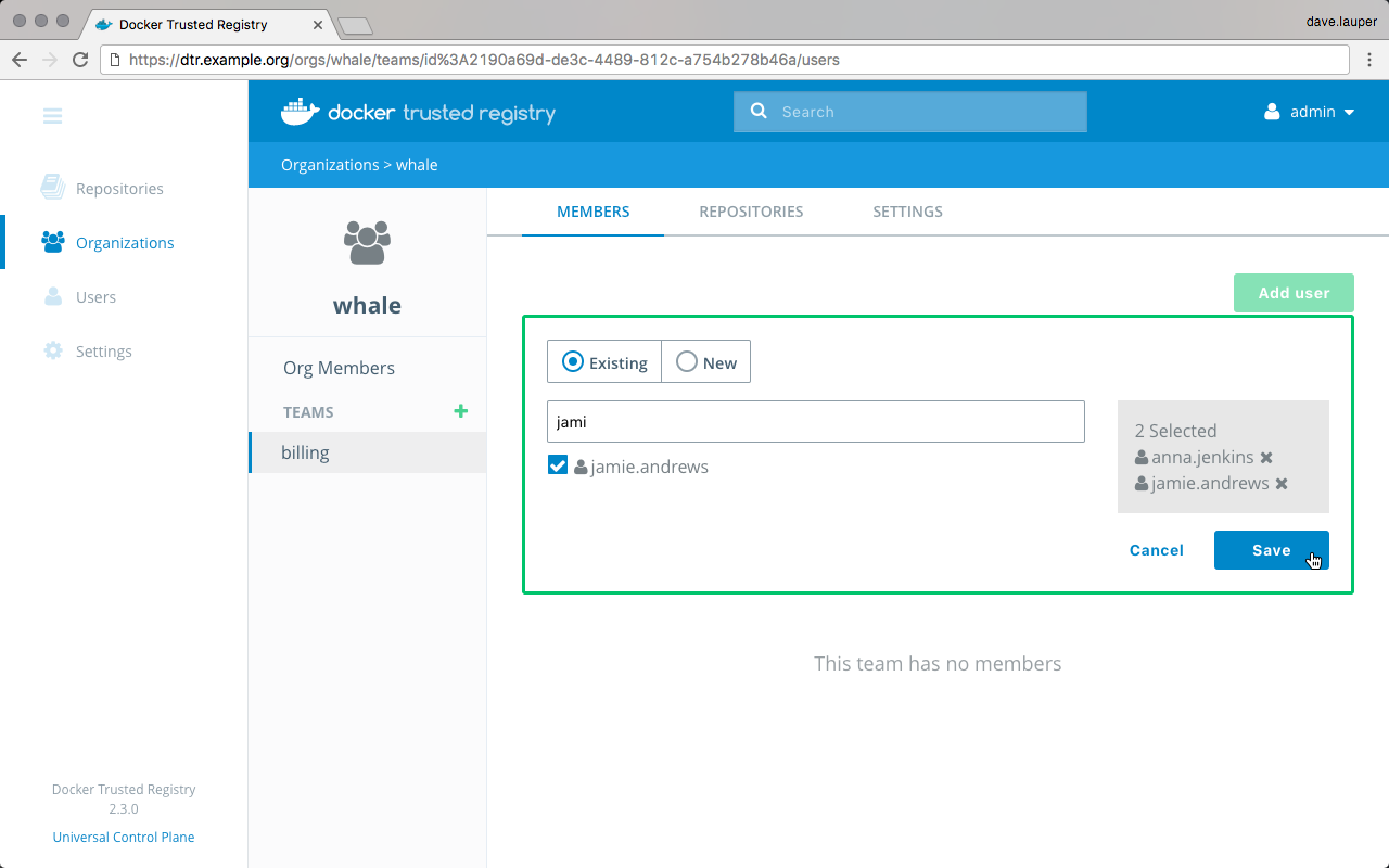
Manage team permissions
The next step is to define the permissions this team has for a set of repositories. Navigate to the Repositories tab, and click the Add repository button.
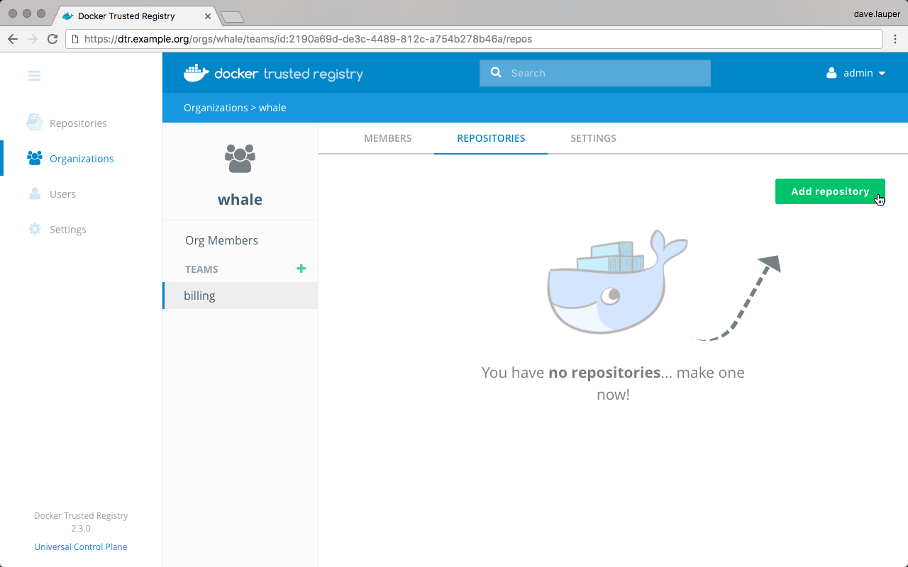
Choose the repositories this team has access to, and what permission levels the team members have.
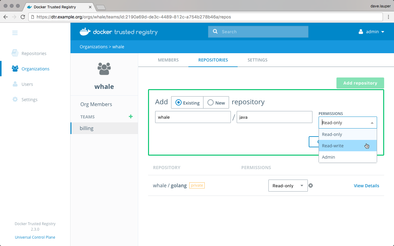
There are three permission levels available:
| Permission level | Description |
|---|---|
| Read only | View repository and pull images. |
| Read & Write | View repository, pull and push images. |
| Admin | Manage repository and change its settings, pull and push images. |
Delete a team
If you’re an organization owner, you can delete a team in that organization. Navigate to the Team, choose the Settings tab, and click Delete.
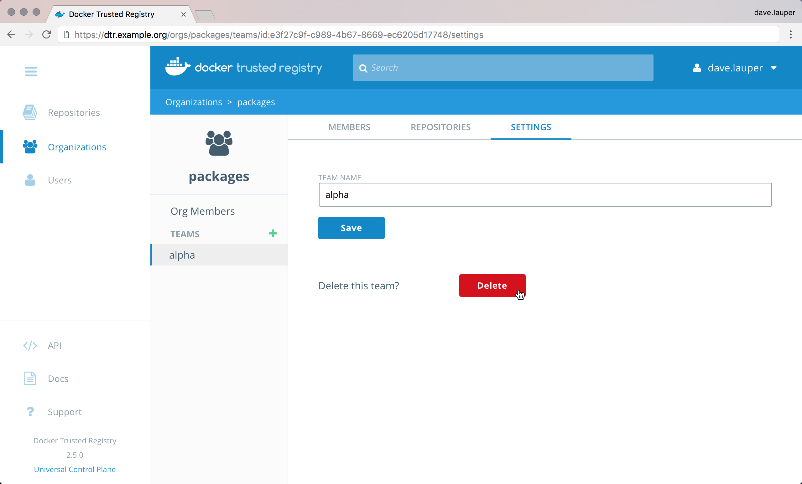
Where to go next
Create and manage organizations
When a user creates a repository, only that user has permissions to make changes to the repository.
For team workflows, where multiple users have permissions to manage a set of common repositories, create an organization. By default, MSR has one organization called ‘docker-datacenter’, that is shared between MKE and MSR.
To create a new organization, navigate to the MSR web UI, and go to the Organizations page.
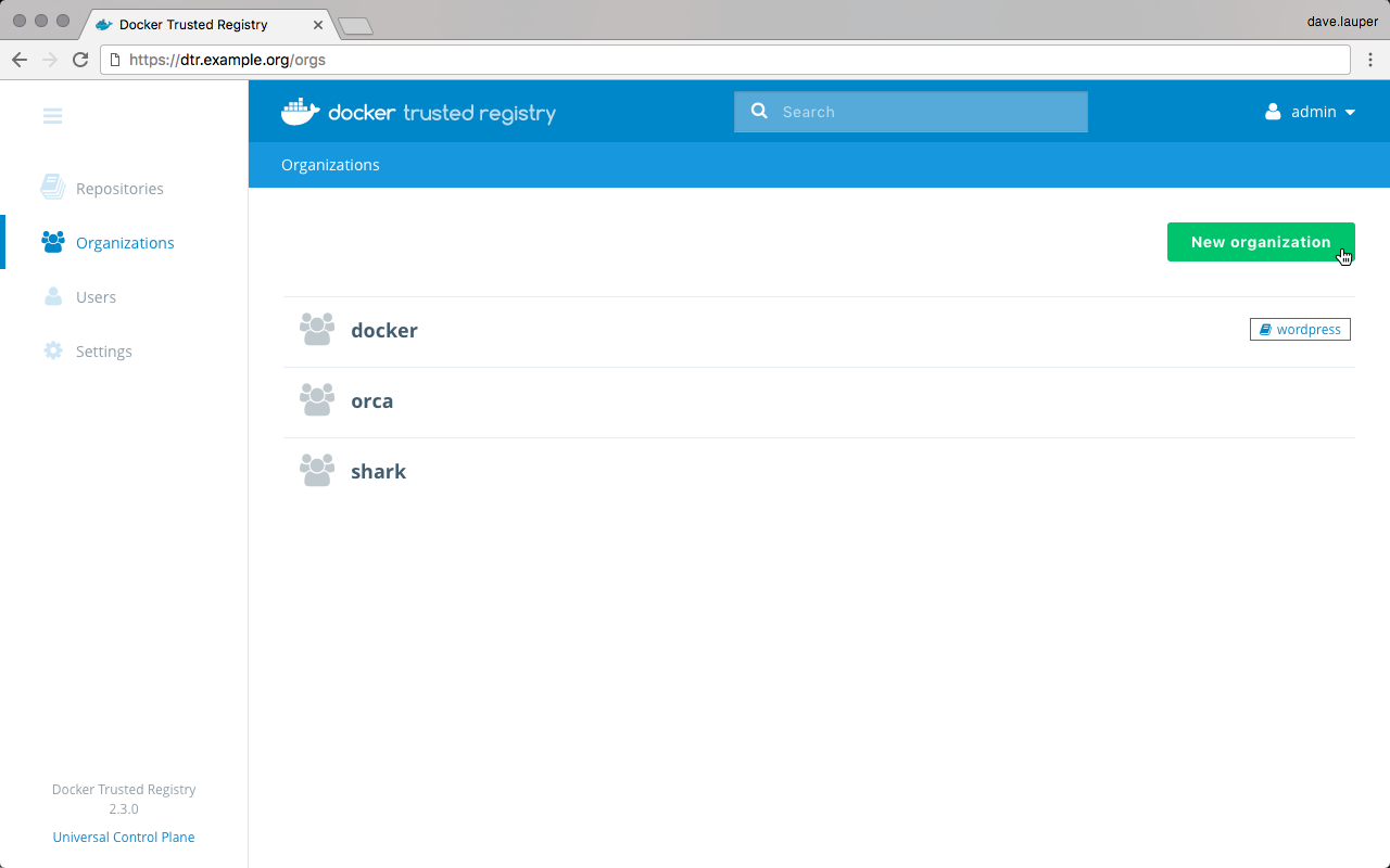
Click the New organization button, and choose a meaningful name for the organization.
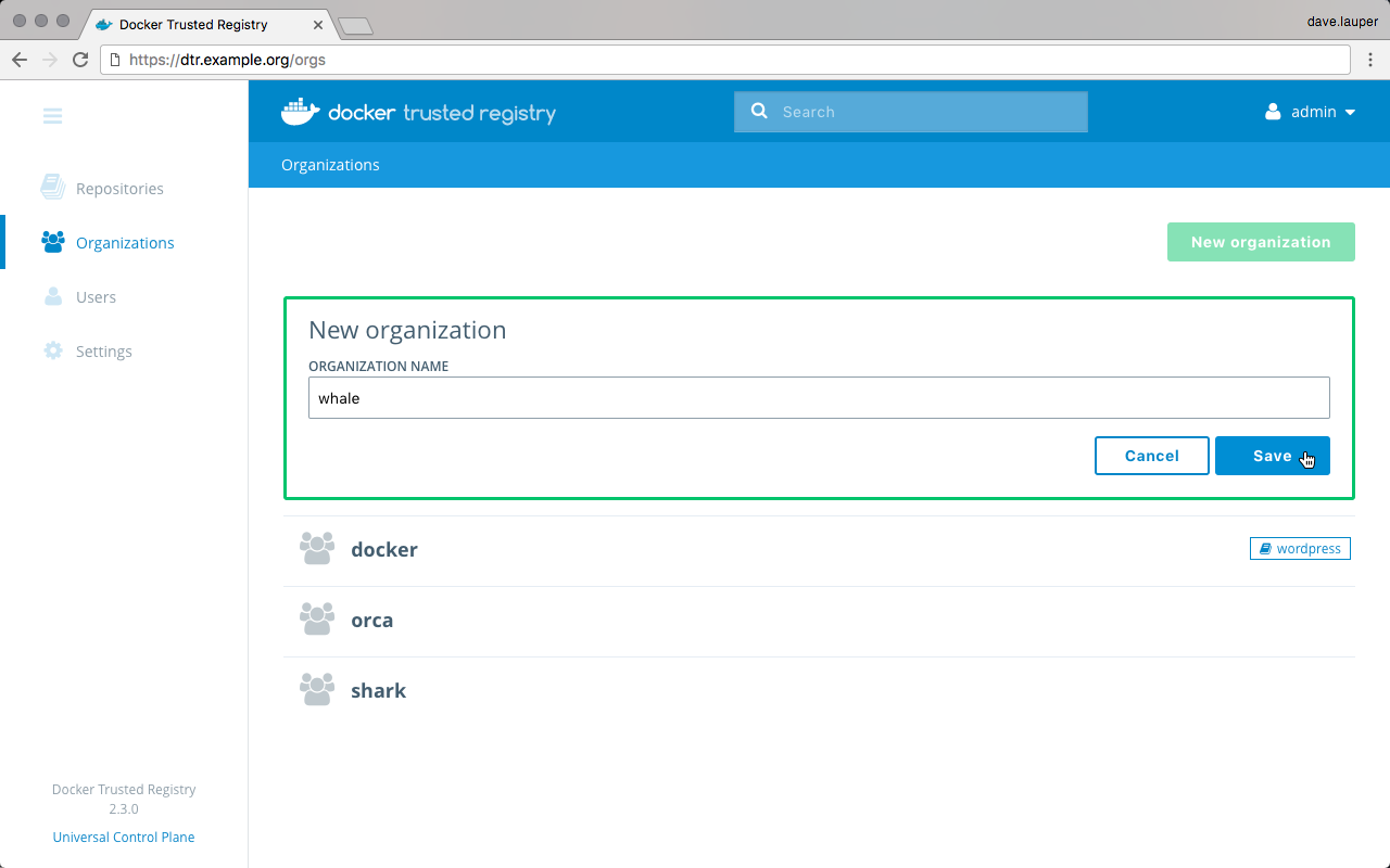
Repositories owned by this organization will contain the organization name, so to pull an image from that repository, you’ll use:
docker pull <msr-domain-name>/<organization>/<repository>:<tag>
Click Save to create the organization, and then click the organization to define which users are allowed to manage this organization. These users will be able to edit the organization settings, edit all repositories owned by the organization, and define the user permissions for this organization.
For this, click the Add user button, select the users that you want to grant permissions to manage the organization, and click Save. Then change their permissions from ‘Member’ to Org Owner.
Where to go next
Permission levels
Mirantis Secure Registry allows you to define fine-grain permissions over image repositories.
Administrators
Users are shared across MKE and MSR. When you create a new user in Mirantis Kubernetes Engine, that user becomes available in MSR and vice versa. When you create a trusted admin in MSR, the admin has permissions to manage:
- Users across MKE and MSR
- MSR repositories and settings
- MKE resources and settings
Team permission levels
Teams allow you to define the permissions a set of user has for a set of repositories. Three permission levels are available:
| Repository operation | read | read-write | admin |
|---|---|---|---|
| View/ browse | x | x | x |
| Pull | x | x | x |
| Push | x | x | |
| Start a scan | x | x | |
| Delete tags | x | x | |
| Edit description | x | ||
| Set public or private | x | ||
| Manage user access | x | ||
| Delete repository | x |
Team permissions are additive. When a user is a member of multiple teams, they have the highest permission level defined by those teams.
Overall permissions
Here’s an overview of the permission levels available in MSR:
- Anonymous or unauthenticated Users: Can search and pull public repositories.
- Authenticated Users: Can search and pull public repos, and create and manage their own repositories.
- Team Member: Everything a user can do, plus the permissions granted by the team the user is a member of.
- Organization Owner: Can manage repositories and teams for the organization.
- Admin: Can manage anything across MKE and MSR.
Where to go next
Manage webhooks
You can configure MSR to automatically post event notifications to a webhook URL of your choosing. This lets you build complex CI and CD pipelines with your Docker images. The following is a complete list of event types you can trigger webhook notifications for via the web interface or the API.
Webhook types
| Event Type | Scope | Access Level | Availability |
|---|---|---|---|
Tag pushed to repository
(TAG_PUSH) |
Individual repositories | Repository admin | Web UI & API |
Tag pulled from repository
(TAG_PULL) |
Individual repositories | Repository admin | Web UI & API |
Tag deleted from repository
(TAG_DELETE) |
Individual repositories | Repository admin | Web UI & API |
| Manifest pushed to repository | Individual repositories | Repository admin | Web UI & API |
Manifest pulled from
repository
(MANIFEST_PULL) |
Individual repositories | Repository admin | Web UI & API |
Manifest deleted from
repository
(MANIFEST_DELETE) |
Individual repositories | Repository admin | Web UI & API |
Security scan completed
(SCAN_COMPLETED) |
Individual repositories | Repository admin | Web UI & API |
Security scan failed
(SCAN_FAILED) |
Individual repositories | Repository admin | Web UI & API |
Image promoted from
repository (PROMOTION) |
Individual repositories | Repository admin | Web UI & API |
Image mirrored from
repository
(PUSH_MIRRORING) |
Individual repositories | Repository admin | Web UI & API |
Image mirrored from remote
repository
(POLL_MIRRORING) |
Individual repositories | Repository admin | Web UI & API |
Repository created, updated,
or deleted
(REPO_CREATED,
REPO_UPDATED, and
REPO_DELETED) |
Namespaces / Organizations | Namespace / Org owners | API Only |
| Security scanner update completed (` SCANNER_UPDATE_COMPLETED`) | Global | MSR admin | API Only |
You must have admin privileges to a repository or namespace in order to subscribe to its webhook events. For example, a user must be an admin of repository “foo/bar” to subscribe to its tag push events. A MSR admin can subscribe to any event.
Where to go next
Manage repository webhooks with the web interface
Prerequisites
- You must have admin privileges to the repository in order to create a webhook.
- See Webhook types for a list of events you can trigger notifications for using the web interface.
Create a webhook for your repository
In your browser, navigate to
https://<msr-url>and log in with your credentials.Select Repositories from the left navigation pane, and then click on the name of the repository that you want to view. Note that you will have to click on the repository name following the
/after the specific namespace for your repository.Select the Webhooks tab, and click New Webhook.
From the drop-down list, select the event that will trigger the webhook.
Set the URL which will receive the JSON payload. Click Test next to the Webhook URL field, so that you can validate that the integration is working. At your specified URL, you should receive a JSON payload for your chosen event type notification.
{ "type": "TAG_PUSH", "createdAt": "2019-05-15T19:39:40.607337713Z", "contents": { "namespace": "foo", "repository": "bar", "tag": "latest", "digest": "sha256:b5bb9d8014a0f9b1d61e21e796d78dccdf1352f23cd32812f4850b878ae4944c", "imageName": "foo/bar:latest", "os": "linux", "architecture": "amd64", "author": "", "pushedAt": "2015-01-02T15:04:05Z" }, "location": "/repositories/foo/bar/tags/latest" }
Expand “Show advanced settings” to paste the TLS certificate associated with your webhook URL. For testing purposes, you can test over HTTP instead of HTTPS.
Click Create to save. Once saved, your webhook is active and starts sending POST notifications whenever your chosen event type is triggered.
As a repository admin, you can add or delete a webhook at any point. Additionally, you can create, view, and delete webhooks for your organization or trusted registry using the API.
Where to go next
Manage repository webhooks with the API
Prerequisite
See Webhook types for a list of events you can trigger notifications for via the API.
API Base URL
Your MSR hostname serves as the base URL for your API requests.
Swagger API explorer
From the MSR web interface, click API on the bottom left navigation pane to explore the API resources and endpoints. Click Execute to send your API request.
API requests via curl
You can use curl to send
HTTP or HTTPS API requests. Note that you will have to specify
skipTLSVerification: true on your request in order to test the
webhook endpoint over HTTP.
curl -u test-user:$TOKEN -X POST "https://dtr-example.com/api/v0/webhooks" -H "accept: application/json" -H "content-type: application/json" -d "{ \"endpoint\": \"https://webhook.site/441b1584-949d-4608-a7f3-f240bdd31019\", \"key\": \"maria-testorg/lab-words\", \"skipTLSVerification\": true, \"type\": \"TAG_PULL\"}"
{
"id": "b7bf702c31601efb4796da59900ddc1b7c72eb8ca80fdfb1b9fecdbad5418155",
"type": "TAG_PULL",
"key": "maria-testorg/lab-words",
"endpoint": "https://webhook.site/441b1584-949d-4608-a7f3-f240bdd31019",
"authorID": "194efd8e-9ee6-4d43-a34b-eefd9ce39087",
"createdAt": "2019-05-22T01:55:20.471286995Z",
"lastSuccessfulAt": "0001-01-01T00:00:00Z",
"inactive": false,
"tlsCert": "",
"skipTLSVerification": true
}
Subscribe to events
To subscribe to events, send a POST request to /api/v0/webhooks
with the following JSON payload:
{
"type": "TAG_PUSH",
"key": "foo/bar",
"endpoint": "https://example.com"
}
The keys in the payload are:
type: The event type to subcribe to.key: The namespace/organization or repo to subscribe to. For example, “foo/bar” to subscribe to pushes to the “bar” repository within the namespace/organization “foo”.endpoint: The URL to send the JSON payload to.
Normal users must supply a “key” to scope a particular webhook event to a repository or a namespace/organization. MSR admins can choose to omit this, meaning a POST event notification of your specified type will be sent for all MSR repositories and namespaces.
Whenever your specified event type occurs, MSR will send a POST request to the given endpoint with a JSON-encoded payload. The payload will always have the following wrapper:
{
"type": "...",
"createdAt": "2012-04-23T18:25:43.511Z",
"contents": {...}
}
typerefers to the event type received at the specified subscription endpoint.contentsrefers to the payload of the event itself. Each event is different, therefore the structure of the JSON object incontentswill change depending on the event type. See Content structure for more details.
Before subscribing to an event, you can view and test your endpoints
using fake data. To send a test payload, send POST request to
/api/v0/webhooks/test with the following payload:
{
"type": "...",
"endpoint": "https://www.example.com/"
}
Change type to the event type that you want to receive. MSR will
then send an example payload to your specified endpoint. The example
payload sent is always the same.
Content structure
Comments after (//) are for informational purposes only, and the
example payloads have been clipped for brevity.
Tag push
{
"namespace": "", // (string) namespace/organization for the repository
"repository": "", // (string) repository name
"tag": "", // (string) the name of the tag just pushed
"digest": "", // (string) sha256 digest of the manifest the tag points to (eg. "sha256:0afb...")
"imageName": "", // (string) the fully-qualified image name including DTR host used to pull the image (eg. 10.10.10.1/foo/bar:tag)
"os": "", // (string) the OS for the tag's manifest
"architecture": "", // (string) the architecture for the tag's manifest
"author": "", // (string) the username of the person who pushed the tag
"pushedAt": "", // (string) JSON-encoded timestamp of when the push occurred
...
}
Tag delete
{
"namespace": "", // (string) namespace/organization for the repository
"repository": "", // (string) repository name
"tag": "", // (string) the name of the tag just deleted
"digest": "", // (string) sha256 digest of the manifest the tag points to (eg. "sha256:0afb...")
"imageName": "", // (string) the fully-qualified image name including DTR host used to pull the image (eg. 10.10.10.1/foo/bar:tag)
"os": "", // (string) the OS for the tag's manifest
"architecture": "", // (string) the architecture for the tag's manifest
"author": "", // (string) the username of the person who deleted the tag
"deletedAt": "", // (string) JSON-encoded timestamp of when the delete occurred
...
}
Manifest push
{
"namespace": "", // (string) namespace/organization for the repository
"repository": "", // (string) repository name
"digest": "", // (string) sha256 digest of the manifest (eg. "sha256:0afb...")
"imageName": "", // (string) the fully-qualified image name including DTR host used to pull the image (eg. 10.10.10.1/foo/bar@sha256:0afb...)
"os": "", // (string) the OS for the manifest
"architecture": "", // (string) the architecture for the manifest
"author": "", // (string) the username of the person who pushed the manifest
...
}
Manifest delete
{
"namespace": "", // (string) namespace/organization for the repository
"repository": "", // (string) repository name
"digest": "", // (string) sha256 digest of the manifest (eg. "sha256:0afb...")
"imageName": "", // (string) the fully-qualified image name including DTR host used to pull the image (eg. 10.10.10.1/foo/bar@sha256:0afb...)
"os": "", // (string) the OS for the manifest
"architecture": "", // (string) the architecture for the manifest
"author": "", // (string) the username of the person who deleted the manifest
"deletedAt": "", // (string) JSON-encoded timestamp of when the delete occurred
...
}
Security scan completed
{
"namespace": "", // (string) namespace/organization for the repository
"repository": "", // (string) repository name
"tag": "", // (string) the name of the tag scanned
"imageName": "", // (string) the fully-qualified image name including DTR host used to pull the image (eg. 10.10.10.1/foo/bar:tag)
"scanSummary": {
"namespace": "", // (string) repository's namespace/organization name
"repository": "", // (string) repository name
"tag": "", // (string) the name of the tag just pushed
"critical": 0, // (int) number of critical issues, where CVSS >= 7.0
"major": 0, // (int) number of major issues, where CVSS >= 4.0 && CVSS < 7
"minor": 0, // (int) number of minor issues, where CVSS > 0 && CVSS < 4.0
"last_scan_status": 0, // (int) enum; see scan status section
"check_completed_at": "", // (string) JSON-encoded timestamp of when the scan completed
...
}
}
Security scan failed
{
"namespace": "", // (string) namespace/organization for the repository
"repository": "", // (string) repository name
"tag": "", // (string) the name of the tag scanned
"imageName": "", // (string) the fully-qualified image name including DTR host used to pull the image (eg. 10.10.10.1/foo/bar@sha256:0afb...)
"error": "", // (string) the error that occurred while scanning
...
}
Repository event (created/updated/deleted)
{
"namespace": "", // (string) repository's namespace/organization name
"repository": "", // (string) repository name
"event": "", // (string) enum: "REPO_CREATED", "REPO_DELETED" or "REPO_UPDATED"
"author": "", // (string) the name of the user responsible for the event
"data": {} // (object) when updating or creating a repo this follows the same format as an API response from /api/v0/repositories/{namespace}/{repository}
}
Security scanner update complete
{
"scanner_version": "",
"scanner_updated_at": "", // (string) JSON-encoded timestamp of when the scanner updated
"db_version": 0, // (int) newly updated database version
"db_updated_at": "", // (string) JSON-encoded timestamp of when the database updated
"success": <true|false> // (bool) whether the update was successful
"replicas": { // (object) a map keyed by replica ID containing update information for each replica
"replica_id": {
"db_updated_at": "", // (string) JSON-encoded time of when the replica updated
"version": "", // (string) version updated to
"replica_id": "" // (string) replica ID
},
...
}
}
- 0: Failed. An error occurred checking an image’s layer
- 1: Unscanned. The image has not yet been scanned
- 2: Scanning. Scanning in progress
- 3: Pending: The image will be scanned when a worker is available
- 4: Scanned: The image has been scanned but vulnerabilities have not yet been checked
- 5: Checking: The image is being checked for vulnerabilities
- 6: Completed: The image has been fully security scanned
View and manage existing subscriptions
To view existing subscriptions, send a GET request to
/api/v0/webhooks. As a normal user (i.e., not a MSR admin), this will
show all of your current subscriptions across every
namespace/organization and repository. As a MSR admin, this will show
every webhook configured for your MSR.
The API response will be in the following format:
[
{
"id": "", // (string): UUID of the webhook subscription
"type": "", // (string): webhook event type
"key": "", // (string): the individual resource this subscription is scoped to
"endpoint": "", // (string): the endpoint to send POST event notifications to
"authorID": "", // (string): the user ID resposible for creating the subscription
"createdAt": "", // (string): JSON-encoded datetime when the subscription was created
},
...
]
For more information, view the API documentation.
You can also view subscriptions for a given resource that you are an admin of. For example, if you have admin rights to the repository “foo/bar”, you can view all subscriptions (even other people’s) from a particular API endpoint. These endpoints are:
GET /api/v0/repositories/{namespace}/{repository}/webhooks: View all webhook subscriptions for a repositoryGET /api/v0/repositories/{namespace}/webhooks: View all webhook subscriptions for a namespace/organization
To delete a webhook subscription, send a DELETE request to
/api/v0/webhooks/{id}, replacing {id} with the webhook
subscription ID which you would like to delete.
Only a MSR admin or an admin for the resource with the event subscription can delete a subscription. As a normal user, you can only delete subscriptions for repositories which you manage.
Where to go next
Manage jobs
Job Queue
Mirantis Secure Registry (MSR) uses a job queue to schedule batch jobs. Jobs are added to a cluster-wide job queue, and then consumed and executed by a job runner within MSR.

All MSR replicas have access to the job queue, and have a job runner component that can get and execute work.
How it works
When a job is created, it is added to a cluster-wide job queue and
enters the waiting state. When one of the MSR replicas is ready to
claim the job, it waits a random time of up to 3 seconds to give
every replica the opportunity to claim the task.
A replica claims a job by adding its replica ID to the job. That way,
other replicas will know the job has been claimed. Once a replica claims
a job, it adds that job to an internal queue, which in turn sorts the
jobs by their scheduledAt time. Once that happens, the replica
updates the job status to running, and starts executing it.
The job runner component of each MSR replica keeps a
heartbeatExpiration entry on the database that is shared by all
replicas. If a replica becomes unhealthy, other replicas notice the
change and update the status of the failing worker to dead. Also,
all the jobs that were claimed by the unhealthy replica enter the
worker_dead state, so that other replicas can claim the job.
Job Types
MSR runs periodic and long-running jobs. The following is a complete list of jobs you can filter for via the user interface or the API.
| Job | Description |
|---|---|
| gc | A garbage collection job that deletes layers associated with deleted images. |
| onlinegc | A garbage collection job that deletes layers associated with deleted images without putting the registry in read-only mode. |
| onlinegc_metadata | A garbage collection job that deletes metadata associated with deleted images. |
| onlinegc_joblogs | A garbage collection job that deletes job logs based on a configured job history setting. |
| metadatastoremigration | A necessary migration that enables the onlinegc feature. |
| sleep | Used for testing the correctness of the jobrunner. It sleeps for 60 seconds. |
| false | Used for testing the correctness of the jobrunner. It runs the false
command and immediately fails. |
| tagmigration | Used for synchronizing tag and manifest information between the MSR database and the storage backend. |
| bloblinkmigration | A DTR 2.1 to 2.2 upgrade process that adds references for blobs to repositories in the database. |
| license_update | Checks for license expiration extensions if online license updates are enabled. |
| scan_check | An image security scanning job. This job does not perform the actual
scanning, rather it spawns scan_check_single jobs (one for each
layer in the image). Once all of the scan_check_single jobs are
complete, this job will terminate. |
| scan_check_single | A security scanning job for a particular layer given by the
parameter: SHA256SUM. This job breaks up the layer into components
and checks each component for vulnerabilities. |
| scan_check_all | A security scanning job that updates all of the currently scanned images to display the latest vulnerabilities. |
| update_vuln_db | A job that is created to update MSR’s vulnerability database. It uses an
Internet connection to check for database updates through
https://dss-cve-updates.docker.com/ and updates the
dtr-scanningstore container if there is a new update available. |
| scannedlayermigration | A DTR 2.4 to 2.5 upgrade process that restructures scanned image data. |
| push_mirror_tag | A job that pushes a tag to another registry after a push mirror policy has been evaluated. |
| poll_mirror | A global cron that evaluates poll mirroring policies. |
| webhook | A job that is used to dispatch a webhook payload to a single endpoint. |
| nautilus_update_db | The old name for the update_vuln_db job. This may be visible on old log files. |
| ro_registry | A user-initiated job for manually switching MSR into read-only mode. |
| tag_pruning | A job for cleaning up unnecessary or unwanted repository tags which can be configured by repository admins. For configuration options, see Tag Pruning. |
Job Status
Jobs can have one of the following status values:
| Status | Description |
|---|---|
| waiting | Unclaimed job waiting to be picked up by a worker. |
| running | The job is currently being run by the specified workerID. |
| done | The job has successfully completed. |
| error | The job has completed with errors. |
| cancel_request | The status of a job is monitored by the worker in the database. If the
job status changes to cancel_request, the job is canceled by the worker. |
| cancel | The job has been canceled and was not fully executed. |
| deleted | The job and its logs have been removed. |
| worker_dead | The worker for this job has been declared dead and the job will not
continue. |
| worker_shutdown | The worker that was running this job has been gracefully stopped. |
| worker_resurrection | The worker for this job has reconnected to the database and will cancel this job. |
| Status | Description |
Where to go next
Audit jobs with the web interface
As of DTR 2.2, admins were able to view and audit jobs within MSR using the API. MSR 2.6 enhances those capabilities by adding a Job Logs tab under System settings on the user interface. The tab displays a sortable and paginated list of jobs along with links to associated job logs.
View Jobs List
To view the list of jobs within MSR, do the following:
Navigate to
https://<msr-url>and log in with your MKE credentials.Select System from the left navigation pane, and then click Job Logs. You should see a paginated list of past, running, and queued jobs. By default, Job Logs shows the latest
10jobs on the first page.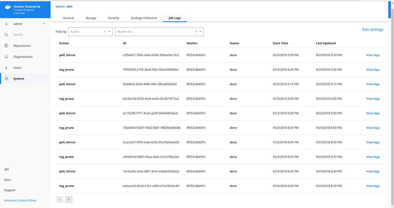
Specify a filtering option. Job Logs lets you filter by:
Action: See Audit Jobs via the API: Job Types for an explanation on the different actions or job types.
Worker ID: The ID of the worker in a MSR replica that is responsible for running the job.
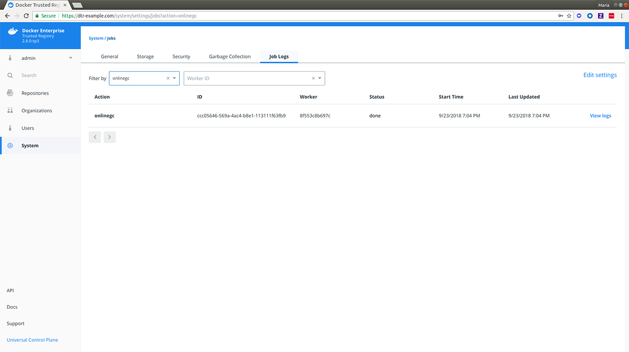
Optional: Click Edit Settings on the right of the filtering options to update your Job Logs settings. See Enable auto-deletion of job logs for more details.
The following is an explanation of the job-related fields displayed in
Job Logs and uses the filtered online_gc action from above.
| Job | Description | Example |
|---|---|---|
| Action | The type of action or job being performed. See Job Types for a full list of job types. | onlinegc |
| ID | The ID of the job. | ccc05646-569a-4ac4-b8e1-113111f63fb9 |
| Worker | The ID of the worker node responsible for running the job. | 8f553c8b697c |
| Status | Current status of the action or job. See Job Status for more details. | done |
| Start Time | Time when the job started. | 9/23/2018 7:04 PM |
| Last Updated | Time when the job was last updated. | 9/23/2018 7:04 PM |
| View Logs | Links to the full logs for the job. | [View Logs] |
View Job-specific Logs
To view the log details for a specific job, do the following:
Click View Logs next to the job’s Last Updated value. You will be redirected to the log detail page of your selected job.

Notice how the job
IDis reflected in the URL while theActionand the abbreviated form of the jobIDare reflected in the heading. Also, the JSON lines displayed are job-specific MSR container logs. See MSR Internal Components for more details.Enter or select a different line count to truncate the number of lines displayed. Lines are cut off from the end of the logs.
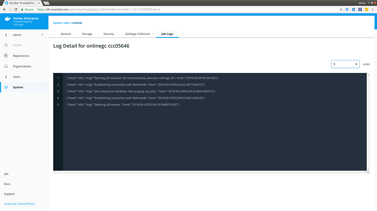
Where to go next
Audit jobs with the API
This covers troubleshooting batch jobs via the API and was introduced in DTR 2.2. Starting in MSR 2.6, admins have the ability to audit jobs using the web interface.
Prerequisite
Each job runner has a limited capacity and will not claim jobs that
require a higher capacity. You can see the capacity of a job runner via
the GET /api/v0/workers endpoint:
{
"workers": [
{
"id": "000000000000",
"status": "running",
"capacityMap": {
"scan": 1,
"scanCheck": 1
},
"heartbeatExpiration": "2017-02-18T00:51:02Z"
}
]
}
This means that the worker with replica ID 000000000000 has a
capacity of 1 scan and 1 scanCheck. Next, review the list of
available jobs:
{
"jobs": [
{
"id": "0",
"workerID": "",
"status": "waiting",
"capacityMap": {
"scan": 1
}
},
{
"id": "1",
"workerID": "",
"status": "waiting",
"capacityMap": {
"scan": 1
}
},
{
"id": "2",
"workerID": "",
"status": "waiting",
"capacityMap": {
"scanCheck": 1
}
}
]
}
If worker 000000000000 notices the jobs in waiting state above,
then it will be able to pick up jobs 0 and 2 since it has the
capacity for both. Job 1 will have to wait until the previous scan
job, 0, is completed. The job queue will then look like:
{
"jobs": [
{
"id": "0",
"workerID": "000000000000",
"status": "running",
"capacityMap": {
"scan": 1
}
},
{
"id": "1",
"workerID": "",
"status": "waiting",
"capacityMap": {
"scan": 1
}
},
{
"id": "2",
"workerID": "000000000000",
"status": "running",
"capacityMap": {
"scanCheck": 1
}
}
]
}
You can get a list of jobs via the GET /api/v0/jobs/ endpoint. Each
job looks like:
{
"id": "1fcf4c0f-ff3b-471a-8839-5dcb631b2f7b",
"retryFromID": "1fcf4c0f-ff3b-471a-8839-5dcb631b2f7b",
"workerID": "000000000000",
"status": "done",
"scheduledAt": "2017-02-17T01:09:47.771Z",
"lastUpdated": "2017-02-17T01:10:14.117Z",
"action": "scan_check_single",
"retriesLeft": 0,
"retriesTotal": 0,
"capacityMap": {
"scan": 1
},
"parameters": {
"SHA256SUM": "1bacd3c8ccb1f15609a10bd4a403831d0ec0b354438ddbf644c95c5d54f8eb13"
},
"deadline": "",
"stopTimeout": ""
}
The JSON fields of interest here are:
id: The ID of the jobworkerID: The ID of the worker in a MSR replica that is running this jobstatus: The current state of the jobaction: The type of job the worker will actually performcapacityMap: The available capacity a worker needs for this job to run
Several of the jobs performed by MSR are run in a recurrent schedule.
You can see those jobs using the GET /api/v0/crons endpoint:
{
"crons": [
{
"id": "48875b1b-5006-48f5-9f3c-af9fbdd82255",
"action": "license_update",
"schedule": "57 54 3 * * *",
"retries": 2,
"capacityMap": null,
"parameters": null,
"deadline": "",
"stopTimeout": "",
"nextRun": "2017-02-22T03:54:57Z"
},
{
"id": "b1c1e61e-1e74-4677-8e4a-2a7dacefffdc",
"action": "update_db",
"schedule": "0 0 3 * * *",
"retries": 0,
"capacityMap": null,
"parameters": null,
"deadline": "",
"stopTimeout": "",
"nextRun": "2017-02-22T03:00:00Z"
}
]
}
The schedule field uses a cron expression following the
(seconds) (minutes) (hours) (day of month) (month) (day of week)
format. For example, 57 54 3 * * * with cron ID
48875b1b-5006-48f5-9f3c-af9fbdd82255 will be run at 03:54:57 on
any day of the week or the month, which is 2017-02-22T03:54:57Z in
the example JSON response above.
Where to go next
Enable auto-deletion of job logs
Mirantis Secure Registry has a global setting for auto-deletion of job logs which allows them to be removed as part of garbage collection. MSR admins can enable auto-deletion of repository events in MSR 2.6 based on specified conditions which are covered below.
Steps
In your browser, navigate to
https://<msr-url>and log in with your MKE credentials.Select System on the left navigation pane which will display the Settings page by default.
Scroll down to Job Logs and turn on Auto-Deletion.
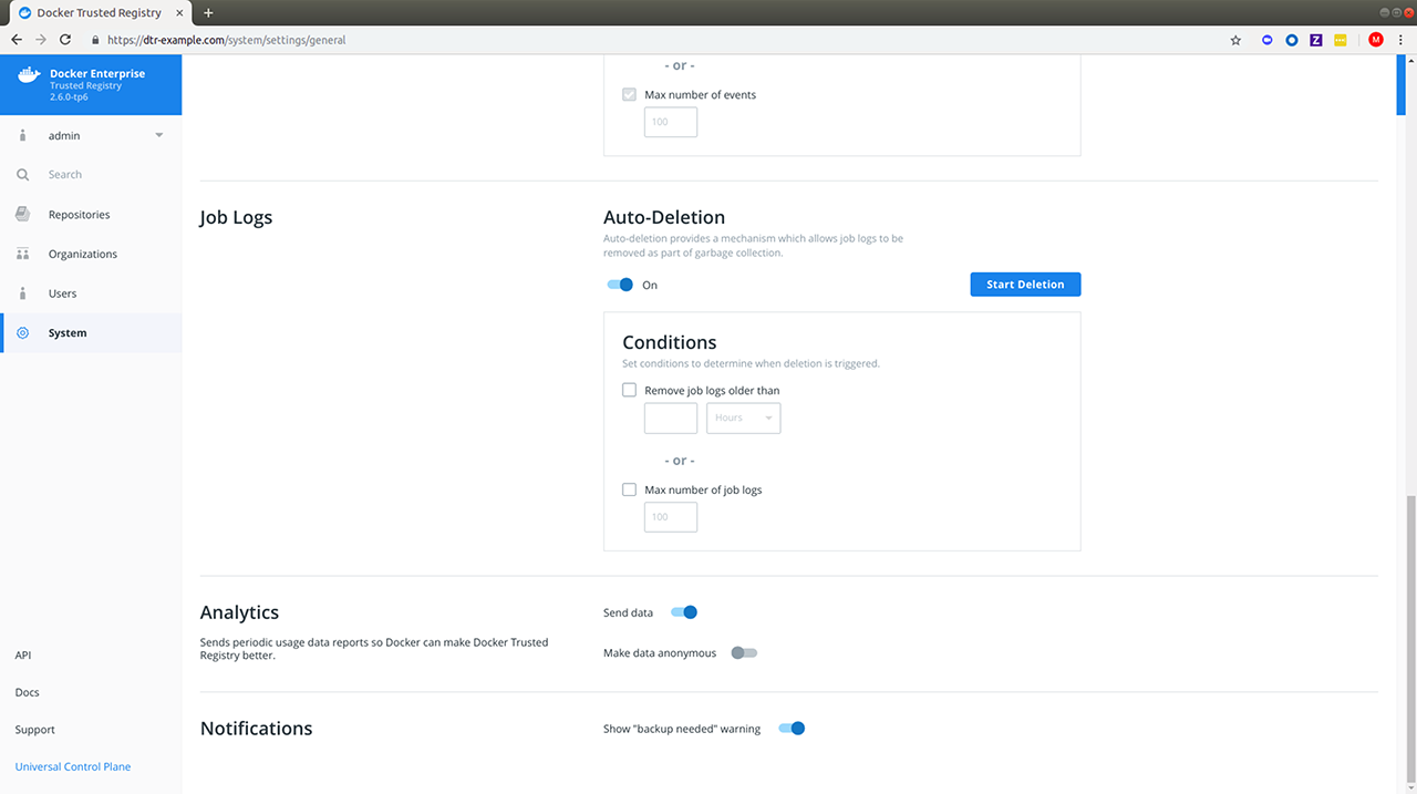
Specify the conditions with which a job log auto-deletion will be triggered.
MSR allows you to set your auto-deletion conditions based on the following optional job log attributes:
Name Description Example Age Lets you remove job logs which are older than your specified number of hours, days, weeks or months 2 monthsMax number of events Lets you specify the maximum number of job logs allowed within MSR. 100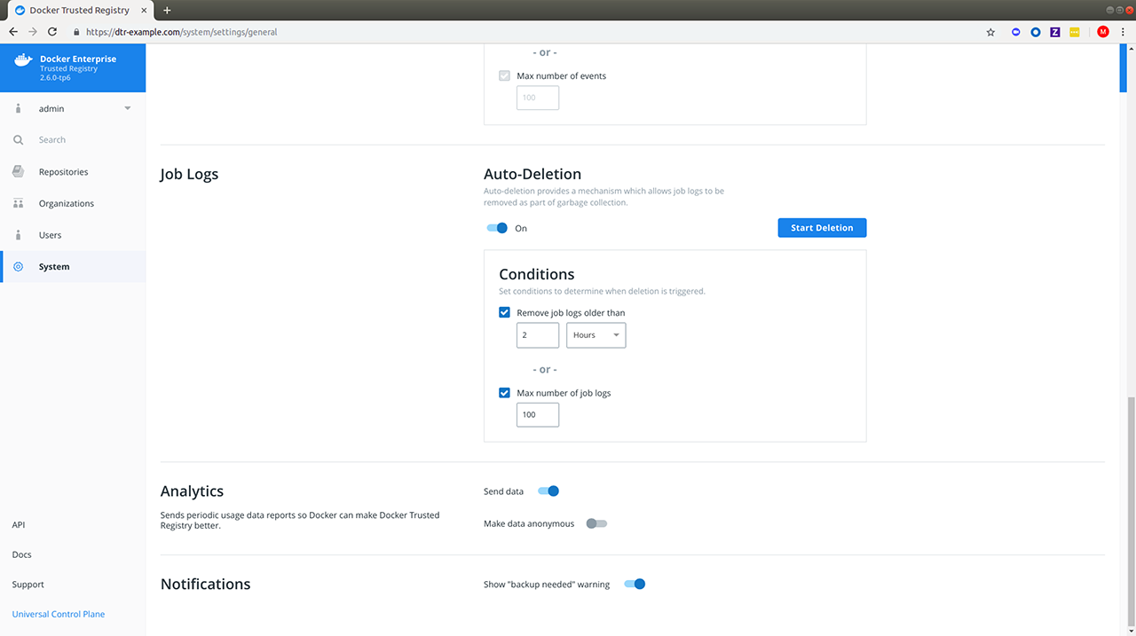
If you check and specify both, job logs will be removed from MSR during garbage collection if either condition is met. You should see a confirmation message right away.
Click Start Deletion if you’re ready. Read more about garbage collection if you’re unsure about this operation.
Navigate to System > Job Logs to confirm that onlinegc_joblogs has started. For a detailed breakdown of individual job logs, see View Job-specific Logs in “Audit Jobs via the Web Interface.”
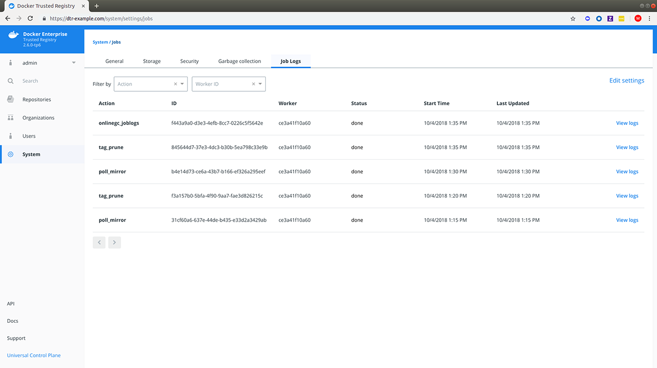
Where to go next
Monitor and troubleshoot
Monitor MSR
Mirantis Secure Registry is a Dockerized application. To monitor it, you can use the same tools and techniques you’re already using to monitor other containerized applications running on your cluster. One way to monitor MSR is using the monitoring capabilities of Mirantis Kubernetes Engine.
In your browser, log in to Mirantis Kubernetes Engine (MKE), and navigate to the Stacks page. If you have MSR set up for high-availability, then all the MSR replicas are displayed.
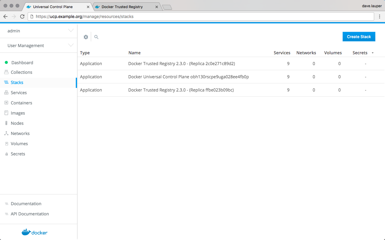
To check the containers for the MSR replica, click the replica you want to inspect, click Inspect Resource, and choose Containers.
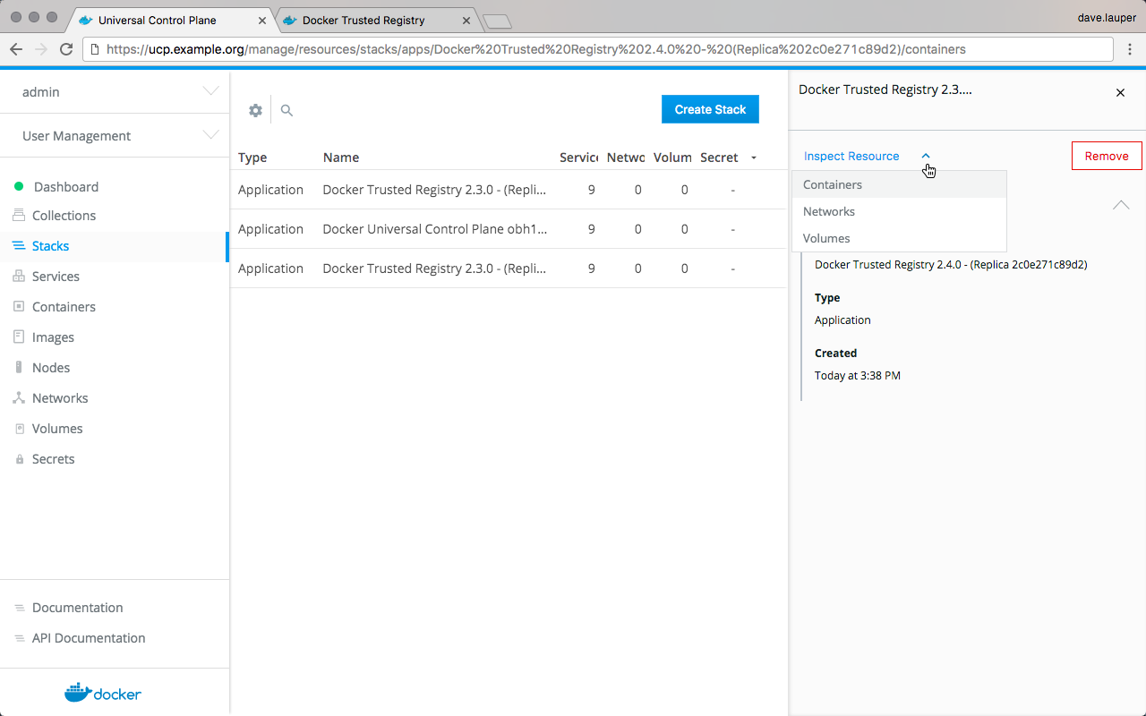
Now you can drill into each MSR container to see its logs and find the root cause of the problem.
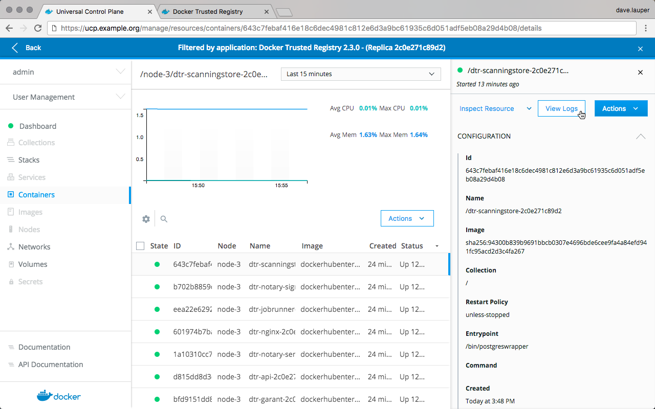
Health check endpoints
MSR also exposes several endpoints you can use to assess if a MSR replica is healthy or not:
/_ping: Checks if the MSR replica is healthy, and returns a simple json response. This is useful for load balancing or other automated health check tasks./nginx_status: Returns the number of connections being handled by the NGINX front-end used by MSR./api/v0/meta/cluster_status: Returns extensive information about all MSR replicas.
Cluster status
The /api/v0/meta/cluster_status endpoint requires administrator
credentials, and returns a JSON object for the entire cluster as observed by
the replica being queried. You can authenticate your requests using HTTP basic
auth.
curl -ksL -u <user>:<pass> https://<msr-domain>/api/v0/meta/cluster_status
{
"current_issues": [
{
"critical": false,
"description": "... some replicas are not ready. The following servers are
not reachable: dtr_rethinkdb_f2277ad178f7",
}],
"replica_health": {
"f2277ad178f7": "OK",
"f3712d9c419a": "OK",
"f58cf364e3df": "OK"
},
}
You can find health status on the current_issues and
replica_health arrays. If this endpoint doesn’t provide meaningful
information when trying to troubleshoot, try troubleshooting using
logs.
Where to go next
Check notary audit logs
Docker Content Trust (DCT) keeps audit logs of changes made to trusted repositories. Every time you push a signed image to a repository, or delete trust data for a repository, DCT logs that information.
These logs are only available from the MSR API.
Get an authentication token
To access the audit logs you need to authenticate your requests using an authentication token. You can get an authentication token for all repositories, or one that is specific to a single repository.
MSR returns a JSON file with a token, even when the user doesn’t have access to the repository to which they requested the authentication token. This token doesn’t grant access to MSR repositories.
The JSON file returned has the following structure:
{
"token": "<token>",
"access_token": "<token>",
"expires_in": "<expiration in seconds>",
"issued_at": "<time>"
}
Changefeed API
Once you have an authentication token you can use the following endpoints to get audit logs:
| URL | Description | Authorization |
|---|---|---|
GET /v2/_trust/changefeed |
Get audit logs for all repositories. | Global scope token |
GET /v2/<msr-url>/<repository>/_trust/changefeed |
Get audit logs for a specific repository. | Repository-specific token |
Both endpoints have the following query string parameters:
| Field name | Required | Type | Description |
|---|---|---|---|
change_id |
Yes | String | A non-inclusive starting change ID from which to start returning results. This will typically be the first or last change ID from the previous page of records requested, depending on which direction your are paging in. The value The value |
records |
Yes | Signed integer | The number of records to return. A negative value indicates the number
of records preceding the change_id should be returned. Records are
always returned sorted from oldest to newest. |
The response is a JSON like:
{
"count": 1,
"records": [
{
"ID": "0a60ec31-d2aa-4565-9b74-4171a5083bef",
"CreatedAt": "2017-11-06T18:45:58.428Z",
"GUN": "dtr.example.org/library/wordpress",
"Version": 1,
"SHA256": "a4ffcae03710ae61f6d15d20ed5e3f3a6a91ebfd2a4ba7f31fc6308ec6cc3e3d",
"Category": "update"
}
]
}
Below is the description for each of the fields in the response:
count |
The number of records returned. |
|---|---|
ID |
The ID of the change record. Should be used in the change_id field
of requests to provide a non-exclusive starting index. It should be
treated as an opaque value that is guaranteed to be unique within an
instance of notary. |
CreatedAt |
The time the change happened. |
GUN |
The MSR repository that was changed. |
Version |
The version that the repository was updated to. This increments every time there’s a change to the trust repository. This is always |
SHA256 |
The checksum of the timestamp being updated to. This can be used with the existing notary APIs to request said timestamp. This is always an empty string for events representing trusted data being removed from the repository |
Category |
The kind of change that was made to the trusted repository. Can be
update, or deletion. |
The results only include audit logs for events that happened more than 60 seconds ago, and are sorted from oldest to newest.
Even though the authentication API always returns a token, the changefeed API validates if the user has access to see the audit logs or not:
- If the user is an admin they can see the audit logs for any repositories,
- All other users can only see audit logs for repositories they have read access.
Example - Get audit logs for all repositories
Before going through this example, make sure that you:
- Are a MSR admin user.
- Configured your machine to trust MSR.
- Created the
library/wordpressrepository. - Installed
jq, to make it easier to parse the JSON responses.
# Pull an image from Docker Hub
docker pull wordpress:latest
# Tag that image
docker tag wordpress:latest <msr-url>/library/wordpress:1
# Log into DTR
docker login <msr-url>
# Push the image to DTR and sign it
DOCKER_CONTENT_TRUST=1 docker push <msr-url>/library/wordpress:1
# Get global-scope authorization token, and store it in TOKEN
export TOKEN=$(curl --insecure --silent \
--user '<user>:<password>' \
'https://<msr-url>/auth/token?realm=dtr&service=dtr&scope=registry:catalog:*' | jq --raw-output .token)
# Get audit logs for all repositories and pretty-print it
# If you pushed the image less than 60 seconds ago, it's possible
# That MSR doesn't show any events. Retry the command after a while.
curl --insecure --silent \
--header "Authorization: Bearer $TOKEN" \
"https://<msr-url>/v2/_trust/changefeed?records=10&change_id=0" | jq .
Example - Get audit logs for a single repository
Before going through this example, make sure that you:
- Configured your machine to trust MSR.
- Created the
library/nginxrepository. - Installed
jq, to make it easier to parse the JSON responses.
# Pull an image from Docker Hub
docker pull nginx:latest
# Tag that image
docker tag nginx:latest <msr-url>/library/nginx:1
# Log into DTR
docker login <msr-url>
# Push the image to DTR and sign it
DOCKER_CONTENT_TRUST=1 docker push <msr-url>/library/nginx:1
# Get global-scope authorization token, and store it in TOKEN
export TOKEN=$(curl --insecure --silent \
--user '<user>:<password>' \
'https://<msr-url>/auth/token?realm=dtr&service=dtr&scope=repository:<msr-url>/<repository>:pull' | jq --raw-output .token)
# Get audit logs for all repositories and pretty-print it
# If you pushed the image less than 60 seconds ago, it's possible that
# Docker Content Trust won't show any events. Retry the command after a while.
curl --insecure --silent \
--header "Authorization: Bearer $TOKEN" \
"https://<msr-url>/v2/<msr-url>/<msr-repo>/_trust/changefeed?records=10&change_id=0" | jq .
Troubleshoot MSR
This guide contains tips and tricks for troubleshooting MSR problems.
Troubleshoot overlay networks
High availability in MSR depends on swarm overlay networking. One way to test if overlay networks are working correctly is to deploy containers to the same overlay network on different nodes and see if they can ping one another.
Use SSH to log into a node and run:
docker run -it --rm \
--net dtr-ol --name overlay-test1 \
--entrypoint sh docker/dtr
Then use SSH to log into another node and run:
docker run -it --rm \
--net dtr-ol --name overlay-test2 \
--entrypoint ping docker/dtr -c 3 overlay-test1
If the second command succeeds, it indicates overlay networking is working correctly between those nodes.
You can run this test with any attachable overlay network and any Docker
image that has sh and ping.
Access RethinkDB directly
MSR uses RethinkDB for persisting data and replicating it across replicas. It might be helpful to connect directly to the RethinkDB instance running on a MSR replica to check the MSR internal state.
Warning
Modifying RethinkDB directly is not supported and may cause problems.
As of v2.5.5, the RethinkCLI has been removed from the
RethinkDB image along with other unused components. You can now run RethinkCLI
from a separate image in the dockerhubenterprise organization. Note that
the commands below are using separate tags for non-interactive and interactive
modes.
Use SSH to log into a node that is running a MSR replica, and run the following:
# List problems in the cluster detected by the current node.
REPLICA_ID=$(docker container ls --filter=name=dtr-rethink --format '{{.Names}}' | cut -d'/' -f2 | cut -d'-' -f3 | head -n 1) && echo 'r.db("rethinkdb").table("current_issues")' | docker run --rm -i --net dtr-ol -v "dtr-ca-${REPLICA_ID}:/ca" -e DTR_REPLICA_ID=$REPLICA_ID dockerhubenterprise/rethinkcli:v2.2.0-ni non-interactive
On a healthy cluster the output will be [].
Starting in DTR 2.5.5, you can run RethinkCLI from a separate image. First, set an environment variable for your MSR replica ID:
REPLICA_ID=$(docker inspect -f '{{.Name}}' $(docker ps -q -f name=dtr-rethink) | cut -f 3 -d '-')
RethinkDB stores data in different databases that contain multiple tables. Run the following command to get into interactive mode and query the contents of the DB:
docker run -it --rm --net dtr-ol -v dtr-ca-$REPLICA_ID:/ca dockerhubenterprise/rethinkcli:v2.3.0 $REPLICA_ID
# List problems in the cluster detected by the current node.
> r.db("rethinkdb").table("current_issues")
[]
# List all the DBs in RethinkDB
> r.dbList()
[ 'dtr2',
'jobrunner',
'notaryserver',
'notarysigner',
'rethinkdb' ]
# List the tables in the dtr2 db
> r.db('dtr2').tableList()
[ 'blob_links',
'blobs',
'client_tokens',
'content_caches',
'events',
'layer_vuln_overrides',
'manifests',
'metrics',
'namespace_team_access',
'poll_mirroring_policies',
'promotion_policies',
'properties',
'pruning_policies',
'push_mirroring_policies',
'repositories',
'repository_team_access',
'scanned_images',
'scanned_layers',
'tags',
'user_settings',
'webhooks' ]
# List the entries in the repositories table
> r.db('dtr2').table('repositories')
[ { enableManifestLists: false,
id: 'ac9614a8-36f4-4933-91fa-3ffed2bd259b',
immutableTags: false,
name: 'test-repo-1',
namespaceAccountID: 'fc3b4aec-74a3-4ba2-8e62-daed0d1f7481',
namespaceName: 'admin',
pk: '3a4a79476d76698255ab505fb77c043655c599d1f5b985f859958ab72a4099d6',
pulls: 0,
pushes: 0,
scanOnPush: false,
tagLimit: 0,
visibility: 'public' },
{ enableManifestLists: false,
id: '9f43f029-9683-459f-97d9-665ab3ac1fda',
immutableTags: false,
longDescription: '',
name: 'testing',
namespaceAccountID: 'fc3b4aec-74a3-4ba2-8e62-daed0d1f7481',
namespaceName: 'admin',
pk: '6dd09ac485749619becaff1c17702ada23568ebe0a40bb74a330d058a757e0be',
pulls: 0,
pushes: 0,
scanOnPush: false,
shortDescription: '',
tagLimit: 1,
visibility: 'public' } ]
Individual DBs and tables are a private implementation detail and may
change in MSR from version to version, but you can always use
dbList() and tableList() to explore the contents and data
structure.
To check on the overall status of your MSR cluster without interacting with RethinkCLI, run the following API request:
curl -u admin:$TOKEN -X GET "https://<msr-url>/api/v0/meta/cluster_status" -H "accept: application/json"
{
"rethink_system_tables": {
"cluster_config": [
{
"heartbeat_timeout_secs": 10,
"id": "heartbeat"
}
],
"current_issues": [],
"db_config": [
{
"id": "339de11f-b0c2-4112-83ac-520cab68d89c",
"name": "notaryserver"
},
{
"id": "aa2e893f-a69a-463d-88c1-8102aafebebc",
"name": "dtr2"
},
{
"id": "bdf14a41-9c31-4526-8436-ab0fed00c2fd",
"name": "jobrunner"
},
{
"id": "f94f0e35-b7b1-4a2f-82be-1bdacca75039",
"name": "notarysigner"
}
],
"server_status": [
{
"id": "9c41fbc6-bcf2-4fad-8960-d117f2fdb06a",
"name": "dtr_rethinkdb_5eb9459a7832",
"network": {
"canonical_addresses": [
{
"host": "dtr-rethinkdb-5eb9459a7832.dtr-ol",
"port": 29015
}
],
"cluster_port": 29015,
"connected_to": {
"dtr_rethinkdb_56b65e8c1404": true
},
"hostname": "9e83e4fee173",
"http_admin_port": "<no http admin>",
"reql_port": 28015,
"time_connected": "2019-02-15T00:19:22.035Z"
},
}
...
]
}
}
Recover from an unhealthy replica
When a MSR replica is unhealthy or down, the MSR web UI displays a warning:
Warning: The following replicas are unhealthy: 59e4e9b0a254; Reasons: Replica reported health too long ago: 2017-02-18T01:11:20Z; Replicas 000000000000, 563f02aba617 are still healthy.
To fix this, you should remove the unhealthy replica from the MSR cluster, and join a new one. Start by running:
docker run -it --rm \
docker/dtr:2.7.5 remove \
--ucp-insecure-tls
And then:
docker run -it --rm \
docker/dtr:2.7.5 join \
--ucp-node <mke-node-name> \
--ucp-insecure-tls
Disaster recovery
Disaster recovery overview
Mirantis Secure Registry is a clustered application. You can join multiple replicas for high availability.
For a MSR cluster to be healthy, a majority of its replicas (n/2 + 1) need to be healthy and be able to communicate with the other replicas. This is also known as maintaining quorum.
This means that there are three failure scenarios possible.
Replica is unhealthy but cluster maintains quorum
One or more replicas are unhealthy, but the overall majority (n/2 + 1) is still healthy and able to communicate with one another.

In this example the MSR cluster has five replicas but one of the nodes stopped working, and the other has problems with the MSR overlay network.
Even though these two replicas are unhealthy the MSR cluster has a majority of replicas still working, which means that the cluster is healthy.
In this case you should repair the unhealthy replicas, or remove them from the cluster and join new ones.
The majority of replicas are unhealthy
A majority of replicas are unhealthy, making the cluster lose quorum, but at least one replica is still healthy, or at least the data volumes for MSR are accessible from that replica.

In this example the MSR cluster is unhealthy but since one replica is still running it’s possible to repair the cluster without having to restore from a backup. This minimizes the amount of data loss.
All replicas are unhealthy
This is a total disaster scenario where all MSR replicas were lost, causing the data volumes for all MSR replicas to get corrupted or lost.

In a disaster scenario like this, you’ll have to restore MSR from an existing backup. Restoring from a backup should be only used as a last resort, since doing an emergency repair might prevent some data loss.
Repair a single replica
When one or more MSR replicas are unhealthy but the overall majority (n/2 + 1) is healthy and able to communicate with one another, your MSR cluster is still functional and healthy.

Given that the MSR cluster is healthy, there’s no need to execute any disaster recovery procedures like restoring from a backup.
Instead, you should:
- Remove the unhealthy replicas from the MSR cluster.
- Join new replicas to make MSR highly available.
Since a MSR cluster requires a majority of replicas to be healthy at all times, the order of these operations is important. If you join more replicas before removing the ones that are unhealthy, your MSR cluster might become unhealthy.
Split-brain scenario
To understand why you should remove unhealthy replicas before joining new ones, imagine you have a five-replica MSR deployment, and something goes wrong with the overlay network connection the replicas, causing them to be separated in two groups.

Because the cluster originally had five replicas, it can work as long as three replicas are still healthy and able to communicate (5 / 2 + 1 = 3). Even though the network separated the replicas in two groups, MSR is still healthy.
If at this point you join a new replica instead of fixing the network problem or removing the two replicas that got isolated from the rest, it’s possible that the new replica ends up in the side of the network partition that has less replicas.

When this happens, both groups now have the minimum amount of replicas needed to establish a cluster. This is also known as a split-brain scenario, because both groups can now accept writes and their histories start diverging, making the two groups effectively two different clusters.
Remove replicas
To remove unhealthy replicas, you’ll first have to find the replica ID of one of the replicas you want to keep, and the replica IDs of the unhealthy replicas you want to remove.
You can find the list of replicas by navigating to Shared Resources > Stacks or Swarm > Volumes (when using swarm mode) on the MKE web interface, or by using the MKE client bundle to run:
docker ps --format "{{.Names}}" | grep dtr
# The list of DTR containers with <node>/<component>-<replicaID>, e.g.
# node-1/dtr-api-a1640e1c15b6
Another way to determine the replica ID is to SSH into a MSR node and run the following:
REPLICA_ID=$(docker inspect -f '{{.Name}}' $(docker ps -q -f name=dtr-rethink) | cut -f 3 -d '-')
&& echo $REPLICA_ID
Then use the MKE client bundle to remove the unhealthy replicas:
docker run -it --rm docker/dtr:2.7.5 remove \
--existing-replica-id <healthy-replica-id> \
--replica-ids <unhealthy-replica-id> \
--ucp-insecure-tls \
--ucp-url <mke-url> \
--ucp-username <user> \
--ucp-password <password>
You can remove more than one replica at the same time, by specifying multiple IDs with a comma.

Join replicas
Once you’ve removed the unhealthy nodes from the cluster, you should join new ones to make sure your cluster is highly available.
Use your MKE client bundle to run the following command which prompts you for the necessary parameters:
docker run -it --rm \
docker/dtr:2.7.5 join \
--ucp-node <mke-node-name> \
--ucp-insecure-tls
Where to go next
Repair a cluster
For a MSR cluster to be healthy, a majority of its replicas (n/2 + 1) need to be healthy and be able to communicate with the other replicas. This is known as maintaining quorum.
In a scenario where quorum is lost, but at least one replica is still accessible, you can use that replica to repair the cluster. That replica doesn’t need to be completely healthy. The cluster can still be repaired as the MSR data volumes are persisted and accessible.

Repairing the cluster from an existing replica minimizes the amount of data lost. If this procedure doesn’t work, you’ll have to restore from an existing backup.
Diagnose an unhealthy cluster
When a majority of replicas are unhealthy, causing the overall MSR
cluster to become unhealthy, operations like docker login,
docker pull, and docker push present internal server error.
Accessing the /_ping endpoint of any replica also returns the same
error. It’s also possible that the MSR web UI is partially or fully
unresponsive.
Perform an emergency repair
Use the mirantis/dtr emergency-repair command to try to repair an
unhealthy MSR cluster, from an existing replica.
This command checks the data volumes for the MSR replica are uncorrupted, redeploys all internal MSR components and reconfigured them to use the existing volumes. It also reconfigures MSR removing all other nodes from the cluster, leaving MSR as a single-replica cluster with the replica you chose.
Start by finding the ID of the MSR replica that you want to repair from. You can find the list of replicas by navigating to Shared Resources > Stacks or Swarm > Volumes (when using swarm mode) on the MKE web interface, or by using a MKE client bundle to run:
docker ps --format "{{.Names}}" | grep dtr
# The list of DTR containers with <node>/<component>-<replicaID>, e.g.
# node-1/dtr-api-a1640e1c15b6
Another way to determine the replica ID is to SSH into a MSR node and run the following:
REPLICA_ID=$(docker inspect -f '{{.Name}}' $(docker ps -q -f name=dtr-rethink) | cut -f 3 -d '-')
&& echo $REPLICA_ID
Then, use your MKE client bundle to run the emergency repair command:
docker run -it --rm docker/dtr:2.7.5 emergency-repair \
--ucp-insecure-tls \
--existing-replica-id <replica-id>
If the emergency repair procedure is successful, your MSR cluster now has a single replica. You should now join more replicas for high availability.

If the emergency repair command fails, try running it again using a different replica ID. As a last resort, you can restore your cluster from an existing backup.
Where to go next
Create a backup
Data managed by MSR
Mirantis Secure Registry maintains data about:
| Data | Description |
|---|---|
| Con figurations | The MSR cluster configurations |
| Repository metadata | The metadata about the repositories and images deployed |
| Access control to repos and images | Permissions for teams and repositories |
| Notary data | Notary tags and signatures |
| Scan results | Security scanning results for images |
| C ertificates and keys | The certificates, public keys, and private keys that are used for mutual TLS communication |
| Images content | The images you push to MSR. This can be stored on the file system of the node running MSR, or other storage system, depending on the configuration |
This data is persisted on the host running MSR, using named volumes.
To perform a backup of a MSR node, run the mirantis/dtr backup <msr-cli-backup> command. This command backs up the following data:
| Data | Backed up | Description |
|---|---|---|
| Configurations | yes | MSR settings |
| Repository metadata | yes | Metadata such as image architecture and size |
| Access control to repos and images | yes | Data about who has access to which images |
| Notary data | yes | Signatures and digests for images that are signed |
| Scan results | yes | Information about vulnerabilities in your images |
| Certificates and keys | yes | TLS certificates and keys used by MSR |
| Image content | no | Needs to be backed up separately, depends on MSR configuration |
| Users, orgs, teams | no | Create a MKE backup to back up this data |
| Vulnerability database | no | Can be redownloaded after a restore |
Back up MSR data
To create a backup of MSR, you need to:
- Back up image content
- Back up MSR metadata
You should always create backups from the same MSR replica, to ensure a smoother restore. If you have not previously performed a backup, the web interface displays a warning for you to do so:
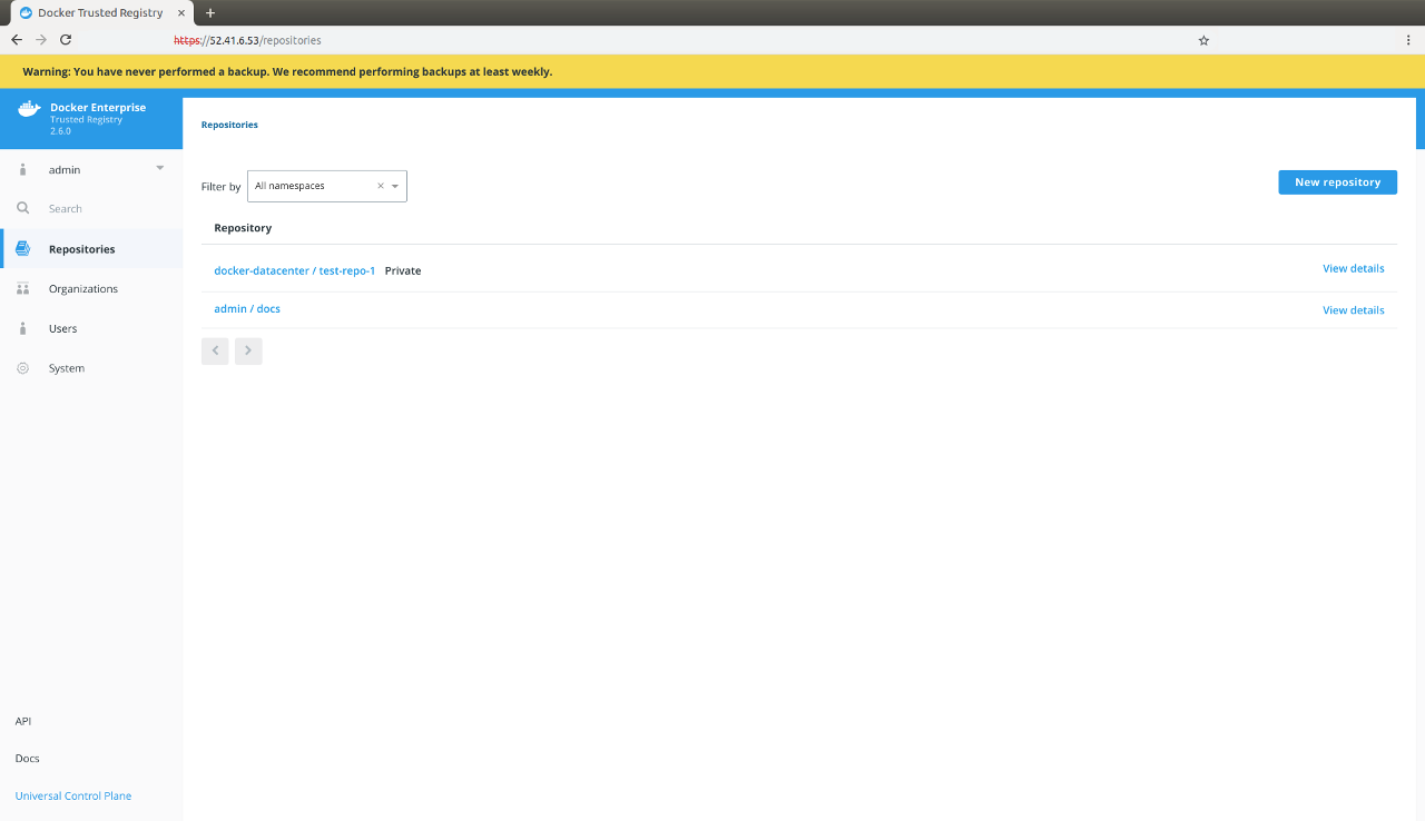
Since you need your MSR replica ID during a backup, the following covers a few ways for you to determine your replica ID:
You can find the list of replicas by navigating to Shared Resources > Stacks or Swarm > Volumes (when using swarm mode) on the MKE web interface.
From a terminal using a MKE client bundle, run:
docker ps --format "{{.Names}}" | grep dtr
# The list of MSR containers with <node>/<component>-<replicaID>, e.g.
# node-1/dtr-api-a1640e1c15b6
Another way to determine the replica ID is to log into a MSR node using SSH and run the following:
REPLICA_ID=$(docker ps --format '{{.Names}}' -f name=dtr-rethink | cut -f 3 -d '-') && echo $REPLICA_ID
Since you can configure the storage backend that MSR uses to store images, the way you back up images depends on the storage backend you’re using.
If you’ve configured MSR to store images on the local file system or NFS
mount, you can back up the images by using SSH to log into a MSR node,
and creating a tar archive of the msr-registry
volume.
sudo tar -cf dtr-image-backup-$(date +%Y%m%d-%H_%M_%S).tar \
/var/lib/docker/volumes/dtr-registry-$(docker ps --format '{{.Names}}' -f name=dtr-rethink | cut -f 3 -d '-')
DTR_VERSION=$(docker container inspect $(docker container ps -f name=dtr-registry -q) | \
grep -m1 -Po '(?<=DTR_VERSION=)\d.\d.\d'); \
REPLICA_ID=$(docker ps --format '{{.Names}}' -f name=dtr-rethink | cut -f 3 -d '-'); \
read -p 'ucp-url (The MKE URL including domain and port): ' UCP_URL; \
read -p 'ucp-username (The MKE administrator username): ' UCP_ADMIN; \
read -sp 'ucp password: ' UCP_PASSWORD; \
docker run --log-driver none -i --rm \
--env UCP_PASSWORD=$UCP_PASSWORD \
docker/dtr:$DTR_VERSION backup \
--ucp-username $UCP_ADMIN \
--ucp-url $UCP_URL \
--ucp-ca "$(curl https://${UCP_URL}/ca)" \
--existing-replica-id $REPLICA_ID > dtr-metadata-${DTR_VERSION}-backup-$(date +%Y%m%d-%H_%M_%S).tar
<mke-url>is the URL you use to access MKE.<mke-username>is the username of a MKE administrator.<mke-password>is the password for the indicated MKE administrator.
The above chained commands run through the following tasks:
- Sets your MSR version and replica ID. To back up a specific replica, set the
replica ID manually by modifying the
--existing-replica-idflag in the backup command. - Prompts you for your MKE URL (domain and port) and admin username.
- Prompts you for your MKE password without saving it to your disk or printing it on the terminal.
- Retrieves the CA certificate for your specified MKE URL. To skip TLS
verification, replace the
--ucp-caflag with--ucp-insecure-tls. Docker does not recommend this flag for production environments. - Includes MSR version and timestamp to your
tarbackup file.
You can learn more about the supported flags in the MSR backup reference documentation.
By default, the backup command does not pause the MSR replica being
backed up to prevent interruptions of user access to MSR. Since the
replica is not stopped, changes that happen during the backup may not be
saved. Use the --offline-backup flag to stop the MSR replica during
the backup procedure. If you set this flag, remove the replica from the
load balancing pool to avoid user interruption.
Also, the backup contains sensitive information like private keys, so you can encrypt the backup by running:
gpg --symmetric {{ metadata_backup_file }}
This prompts you for a password to encrypt the backup, copies the backup file and encrypts it.
To validate that the backup was correctly performed, you can print the contents of the tar file created. The backup of the images should look like:
tar -tf {{ images_backup_file }}
dtr-backup-v2.7.5/
dtr-backup-v2.7.5/rethink/
dtr-backup-v2.7.5/rethink/layers/
And the backup of the MSR metadata should look like:
tar -tf {{ metadata_backup_file }}
# The archive should look like this
dtr-backup-v2.7.5/
dtr-backup-v2.7.5/rethink/
dtr-backup-v2.7.5/rethink/properties/
dtr-backup-v2.7.5/rethink/properties/0
If you’ve encrypted the metadata backup, you can use:
gpg -d {{ metadata_backup_file }} | tar -t
You can also create a backup of a MKE cluster and restore it into a new cluster. Then restore MSR on that new cluster to confirm that everything is working as expected.
Restore from backup
Restore MSR data
If your MSR has a majority of unhealthy replicas, the one way to restore it to a working state is by restoring from an existing backup.
To restore MSR, you need to:
- Stop any MSR containers that might be running
- Restore the images from a backup
- Restore MSR metadata from a backup
- Re-fetch the vulnerability database
You need to restore MSR on the same MKE cluster where you’ve created the backup. If you restore on a different MKE cluster, all MSR resources will be owned by users that don’t exist, so you’ll not be able to manage the resources, even though they’re stored in the MSR data store.
When restoring, you need to use the same version of the mirantis/dtr
image that you’ve used when creating the update. Other versions are not
guaranteed to work.
Start by removing any MSR container that is still running:
docker run -it --rm \
docker/dtr:2.7.5 destroy \
--ucp-insecure-tls
If you had MSR configured to store images on the local filesystem, you can extract your backup:
sudo tar -xf {{ image_backup_file }} -C /var/lib/docker/volumes
If you’re using a different storage backend, follow the best practices recommended for that system.
You can restore the MSR metadata with the mirantis/dtr restore
command. This performs a fresh installation of MSR, and reconfigures it
with the configuration created during a backup.
Load your MKE client bundle, and run the following command, replacing the placeholders for the real values:
read -sp 'ucp password: ' UCP_PASSWORD;
This prompts you for the MKE password. Next, run the following to restore MSR from your backup. You can learn more about the supported flags in mirantis/dtr restore.
docker run -i --rm \
--env UCP_PASSWORD=$UCP_PASSWORD \
docker/dtr:2.7.5 restore \
--ucp-url <mke-url> \
--ucp-insecure-tls \
--ucp-username <mke-username> \
--ucp-node <hostname> \
--replica-id <replica-id> \
--dtr-external-url <msr-external-url> < {{ metadata_backup_file }}
Where:
<mke-url>is the url you use to access MKE<mke-username>is the username of a MKE administrator<hostname>is the hostname of the node where you’ve restored the images<replica-id>the id of the replica you backed up<msr-external-url>the url that clients use to access MSR
If you’re using NFS as a storage backend, also include
--nfs-storage-url as part of your restore command, otherwise DTR is
restored but starts using a local volume to persist your Docker images.
Warning
When running DTR 2.5 (with experimental online garbage collection) and MSR
2.6.0 to 2.6.3, there is an issue with reconfiguring and restoring MSR with
--nfs-storage-url which leads to erased tags. Make sure to back up
your MSR metadata before you proceed. To work around
the --nfs-storage-urlflag issue, manually create a storage volume on
each DTR node. To restore DTR from an existing
backup, use mirantis/dtr restore with --dtr-storage-volume and the
new volume.
See Restore to a Local NFS Volume for Docker’s recommended recovery strategy.
If you’re scanning images, you now need to download the vulnerability database.
After you successfully restore MSR, you can join new replicas the same way you would after a fresh installation. Learn more.
Where to go next
MSR user guides
Access MSR
Configure your Mirantis Container Runtime
By default Mirantis Container Runtime uses TLS when pushing and pulling images to an image registry like Mirantis Secure Registry.
If MSR is using the default configurations or was configured to use self-signed certificates, you need to configure your Mirantis Container Runtime to trust MSR. Otherwise, when you try to log in, push to, or pull images from MSR, you’ll get an error:
docker login dtr.example.org
x509: certificate signed by unknown authority
The first step to make your Mirantis Container Runtime trust the certificate authority used by MSR is to get the MSR CA certificate. Then you configure your operating system to trust that certificate.
Configure your host
In your browser navigate to https://<msr-url>/ca to download the TLS
certificate used by MSR. Then add that certificate to macOS
Keychain.
After adding the CA certificate to Keychain, restart Docker Desktop for Mac.
In your browser navigate to https://<msr-url>/ca to download the TLS
certificate used by MSR. Open Windows Explorer, right-click the file
you’ve downloaded, and choose Install certificate.
Then, select the following options:
- Store location: local machine
- Check place all certificates in the following store
- Click Browser, and select Trusted Root Certificate Authorities
- Click Finish
Learn more about managing TLS certificates.
After adding the CA certificate to Windows, restart Docker Desktop for Windows.
# Download the DTR CA certificate
sudo curl -k https://<msr-domain-name>/ca -o /usr/local/share/ca-certificates/<msr-domain-name>.crt
# Refresh the list of certificates to trust
sudo update-ca-certificates
# Restart the Docker daemon
sudo service docker restart
# Download the DTR CA certificate
sudo curl -k https://<msr-domain-name>/ca -o /etc/pki/ca-trust/source/anchors/<msr-domain-name>.crt
# Refresh the list of certificates to trust
sudo update-ca-trust
# Restart the Docker daemon
sudo /bin/systemctl restart docker.service
Log into the virtual machine with ssh:
docker-machine ssh <machine-name>
Create the
bootsync.shfile, and make it executable:sudo touch /var/lib/boot2docker/bootsync.sh sudo chmod 755 /var/lib/boot2docker/bootsync.sh
Add the following content to the
bootsync.shfile. You can use nano or vi for this.#!/bin/sh cat /var/lib/boot2docker/server.pem >> /etc/ssl/certs/ca-certificates.crt
Add the MSR CA certificate to the
server.pemfile:curl -k https://<msr-domain-name>/ca | sudo tee -a /var/lib/boot2docker/server.pem
Run
bootsync.shand restart the Docker daemon:sudo /var/lib/boot2docker/bootsync.sh sudo /etc/init.d/docker restart
Log into MSR
To validate that your Docker daemon trusts MSR, try authenticating against MSR.
docker login dtr.example.org
Where to go next
Configure your Notary client
Configure your Notary client as described in Delegations for content trust.
Use a cache
Mirantis Secure Registry can be configured to have one or more caches. This allows you to choose from which cache to pull images from for faster download times.
If an administrator has set up caches, you can choose which cache to use when pulling images.
In the MSR web UI, navigate to your Account, and check the Content Cache options.
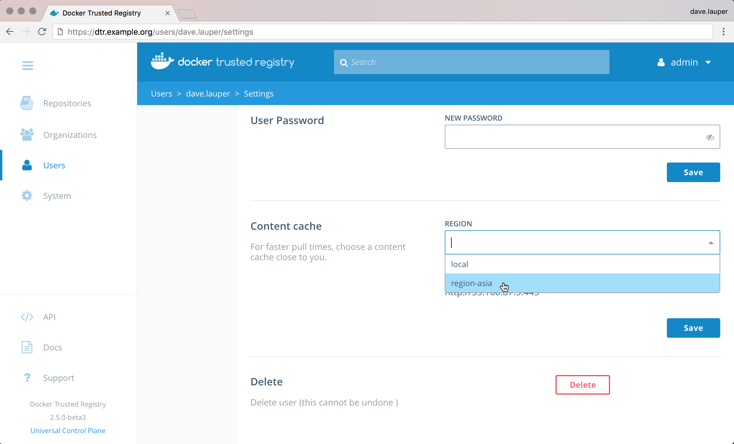
Once you save, your images are pulled from the cache instead of the central MSR.
Manage images
Create a repository
Since MSR is secure by default, you need to create the image repository before being able to push the image to MSR.
In this example, we’ll create the wordpress repository in MSR.
To create an image repository for the first time, log in to
https://<msr-url>with your MKE credentials.Select Repositories from the left navigation pane and click New repository on the upper right corner of the Repositories page.

Select your namespace and enter a name for your repository (upper case letters and some special characters not accepted). You can optionally add a description.
Choose whether your repository is
publicorprivate:Public repositories are visible to all users, but can only be changed by users with write permissions to them.
Private repositories can only be seen by users that have been granted permissions to that repository.
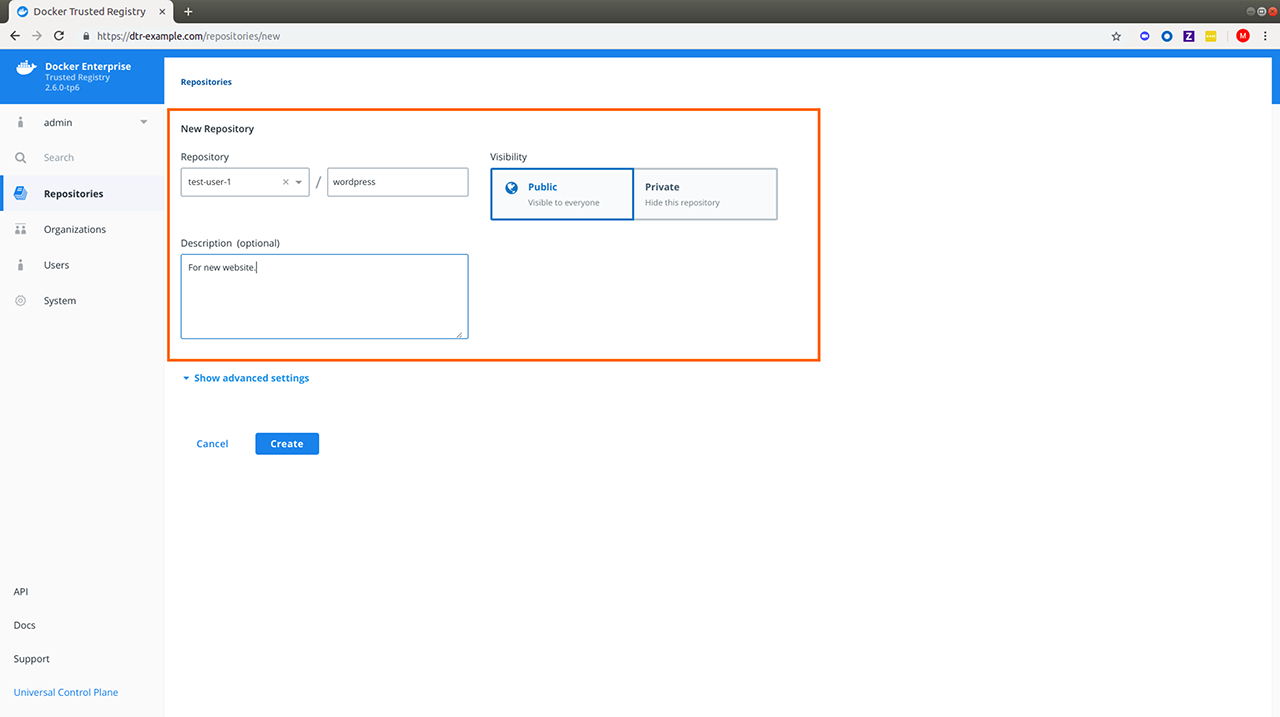
Click Create to create the repository.
When creating a repository in MSR, the full name of the repository becomes
<msr-domain-name>/<user-or-org>/<repository-name>. In this example, the full name of our repository will bedtr-example.com/test-user-1/wordpress.Optional: Click Show advanced settings to make your tags immutable or set your image scanning trigger.
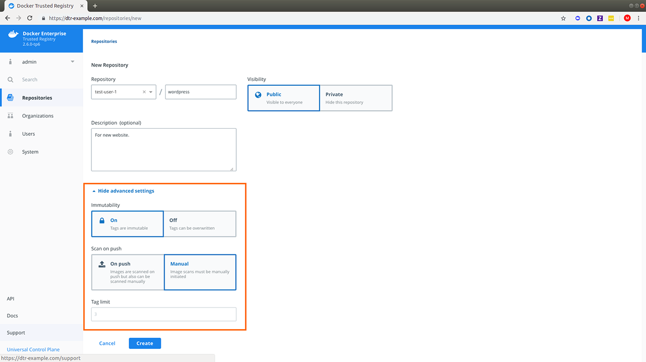
Note
Starting in MSR 2.6, repository admins can enable tag pruning by setting a tag limit. This can only be set if you turn off Immutability and allow your repository tags to be overwritten.
Image name size for MSR
When creating an image name for use with MSR ensure that the organization and repository name has less than 56 characters and that the entire image name which includes domain, organization and repository name does not exceed 255 characters.
The 56-character <user-or-org/repository-name> limit in MSR is due to an underlying limitation in how the image name information is stored within MSR metadata in RethinkDB. RethinkDB currently has a Primary Key length limit of 127 characters.
When MSR stores the above data it appends a sha256sum comprised of 72 characters to the end of the value to ensure uniqueness within the database. If the <user-or-org/repository-name> exceeds 56 characters it will then exceed the 127 character limit in RethinkDB (72+56=128).
Multi-architecture images
While you can enable just-in-time creation of multi-archictecture image repositories when creating a repository via the API, Docker does not recommend using this option. This breaks content trust and causes other issues. To manage Docker image manifests and manifest lists, use the experimental CLI command, docker manifest, instead.
Where to go next
Review repository info
The Repository Info tab includes the following details:
- README (which you can edit if you have admin rights to the repository)
- Docker Pull Command
- Your repository permissions
To learn more about pulling images, see Pull and push images. To review your repository permissions, do the following:
Navigate to
https://<msr-url>and log in with your MKE credentials.Select Repositories on the left navigation pane, and then click on the name of the repository that you want to view. Note that you will have to click on the repository name following the
/after the specific namespace for your repository.
You should see the Info tab by default. Notice Your Permission under Docker Pull Command.
Hover over the question mark next to your permission level to view the list of repository events you have access to.
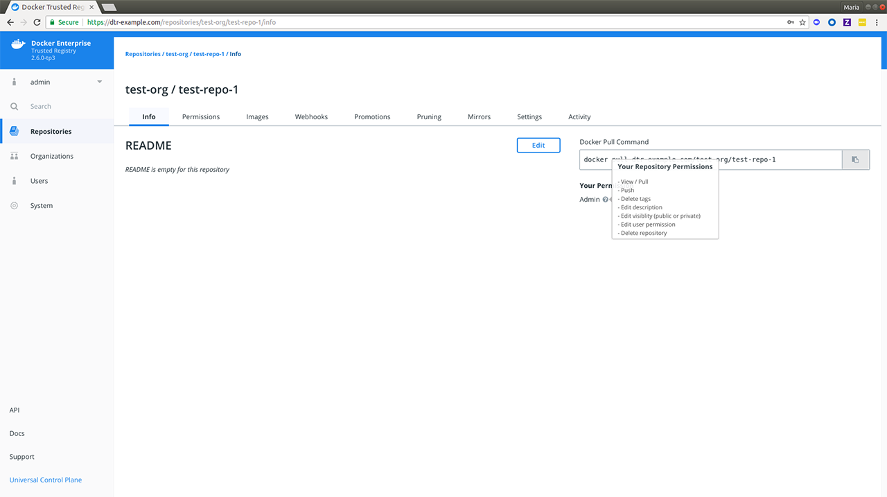
Limitations
Your permissions list may include repository events that are not displayed in the Activity tab. It is also not an exhaustive list of event types displayed on your activity stream. To learn more about repository events, see Audit Repository Events.
Where to go next
Pull and push images
You interact with Mirantis Secure Registry in the same way you interact with Docker Hub or any other registry:
docker login <msr-url>: authenticates you on MSRdocker pull <image>:<tag>: pulls an image from MSRdocker push <image>:<tag>: pushes an image to MSR
Pull an image
Pulling an image from Mirantis Secure Registry is the same as pulling an image from Docker Hub or any other registry. Since MSR is secure by default, you always need to authenticate before pulling images.
In this example, MSR can be accessed at dtr-example.com, and the user was
granted permissions to access the nginx and wordpress
repositories in the library organization.
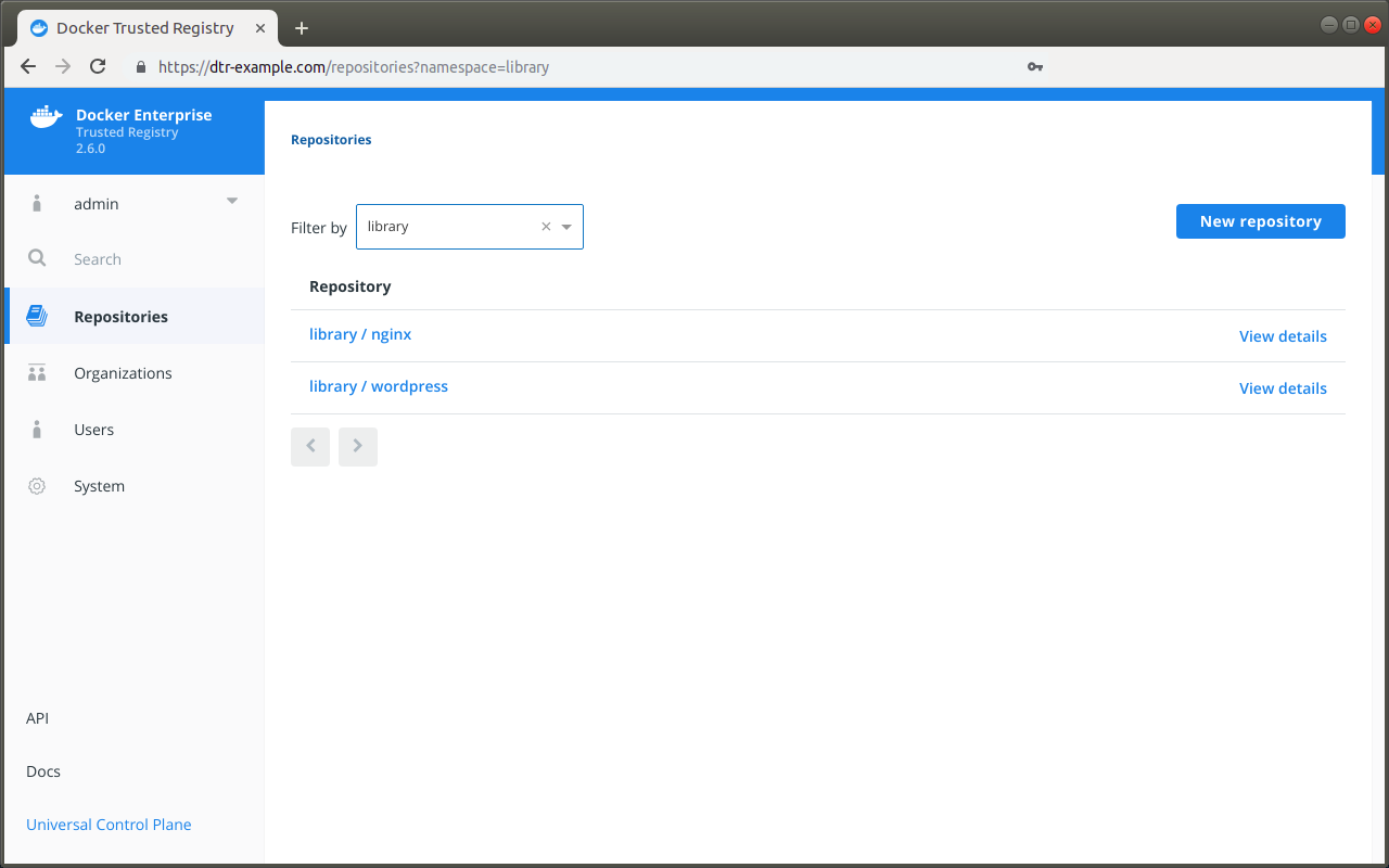
Click on the repository name to see its details.
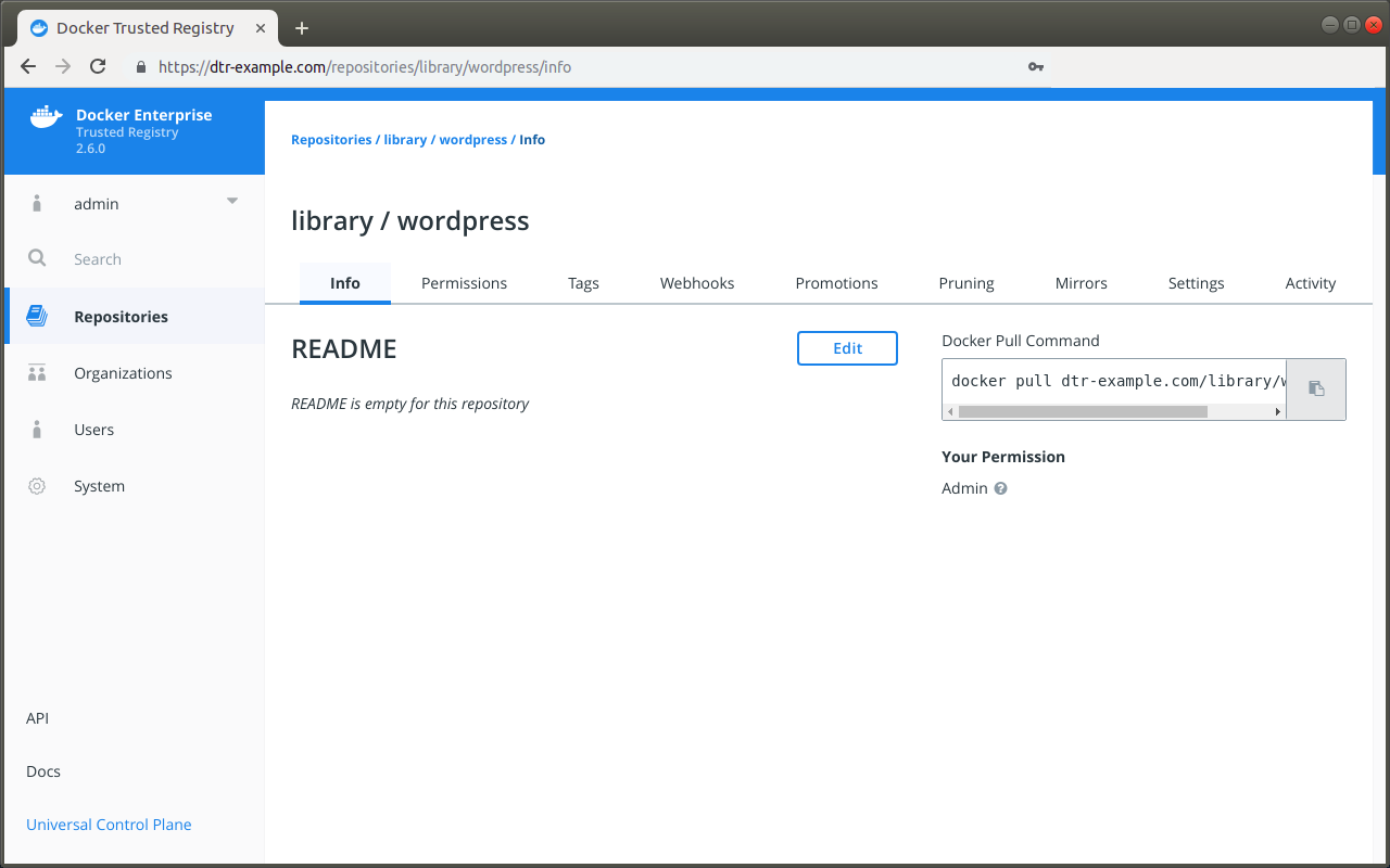
To pull the latest tag of the library/wordpress image, run:
docker login dtr-example.com
docker pull dtr-example.com/library/wordpress:latest
Push an image
Before you can push an image to MSR, you need to create a
repository to store the image. In this example the full
name of our repository is dtr-example.com/library/wordpress.
In this example we’ll pull the wordpress image from Docker Hub and tag with the full MSR and repository name. A tag defines where the image was pulled from, and where it will be pushed to.
# Pull from Docker Hub the latest tag of the wordpress image
docker pull wordpress:latest
# Tag the wordpress:latest image with the full repository name we've created in MSR
docker tag wordpress:latest dtr-example.com/library/wordpress:latest
Now that you have tagged the image, you only need to authenticate and push the image to MSR.
docker login dtr-example.com
docker push dtr-example.com/library/wordpress:latest
On the web interface, navigate to the Tags tab on the repository page to confirm that the tag was successfully pushed.
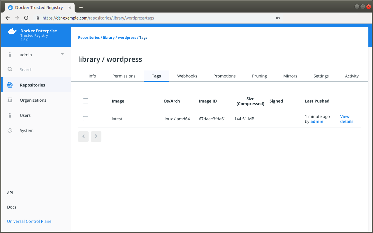
The base layers of the Microsoft Windows base images have restrictions on how they can be redistributed. When you push a Windows image to MSR, Docker only pushes the image manifest and all the layers on top of the Windows base layers. The Windows base layers are not pushed to MSR. This means that:
- MSR won’t be able to scan those images for vulnerabilities since MSR doesn’t have access to the layers (the Windows base layers are scanned by Docker Hub, however).
- When a user pulls a Windows image from MSR, the Windows base layers are automatically fetched from Microsoft and the other layers are fetched from MSR.
This default behavior is recommended for Mirantis Container Runtime installations, but for air-gapped or similarly limited setups Docker can optionally optionally also push the Windows base layers to MSR.
To configure Docker to always push Windows layers to MSR, add the
following to your C:\ProgramData\docker\config\daemon.json
configuration file:
"allow-nondistributable-artifacts": ["<msr-domain>:<msr-port>"]
Where to go next
Delete images
To delete an image, navigate to the Tags tab of the repository page on the MSR web interface. In the Tags tab, select all the image tags you want to delete, and click the Delete button.
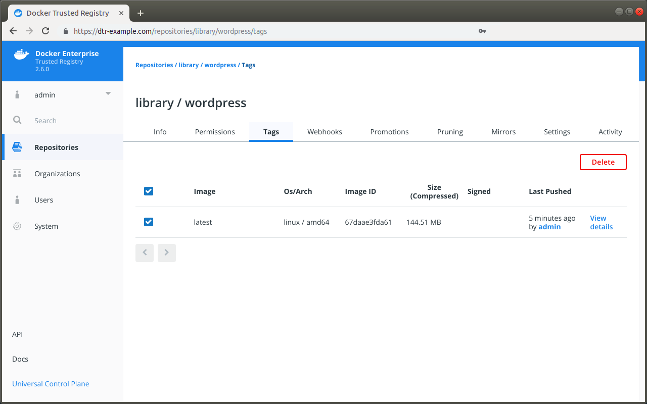
You can also delete all image versions by deleting the repository. To delete a repository, navigate to Settings and click Delete under Delete Repository.
Delete signed images
MSR only allows deleting images if the image has not been signed. You first need to delete all the trust data associated with the image before you are able to delete the image.
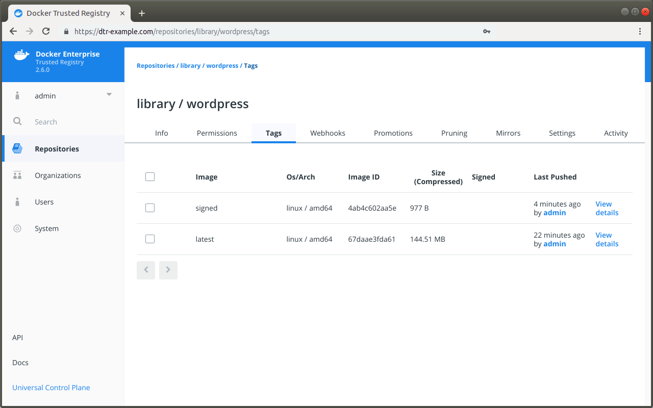
There are three steps to delete a signed image:
- Find which roles signed the image.
- Remove the trust data for each role.
- The image is now unsigned, so you can delete it.
To find which roles signed an image, you first need to learn which roles are trusted to sign the image.
Configure your Notary client and run:
notary delegation list dtr-example.com/library/wordpress
In this example, the repository owner delegated trust to the
targets/releases and targets/qa roles:
ROLE PATHS KEY IDS THRESHOLD
---- ----- ------- ---------
targets/releases "" <all paths> c3470c45cefde5...2ea9bc8 1
targets/qa "" <all paths> c3470c45cefde5...2ea9bc8 1
Now that you know which roles are allowed to sign images in this repository, you can learn which roles actually signed it:
# Check if the image was signed by the "targets" role
notary list dtr-example.com/library/wordpress
# Check if the image was signed by a specific role
notary list dtr-example.com/library/wordpress --roles <role-name>
In this example the image was signed by three roles: targets,
targets/releases, and targets/qa.
Once you know which roles signed an image, you’ll be able to remove trust data for those roles. Only users with private keys that have the roles are able to do this operation.
For each role that signed the image, run:
notary remove dtr-example.com/library/wordpress <tag> \
--roles <role-name> --publish
Once you’ve removed trust data for all roles, MSR shows the image as unsigned. Then you can delete it.
Where to go next
Scan images for vulnerabilities
Mirantis Secure Registry can scan images in your repositories to verify that they are free from known security vulnerabilities or exposures, using Docker Security Scanning. The results of these scans are reported for each image tag in a repository.
Docker Security Scanning is available as an add-on to Mirantis Secure Registry, and an administrator configures it for your MSR instance. If you do not see security scan results available on your repositories, your organization may not have purchased the Security Scanning feature or it may be disabled. See Set up Security Scanning in MSR for more details.
Note
Only users with write access to a repository can manually start a scan. Users with read-only access can view the scan results, but cannot start a new scan.
The Docker Security Scan process
Scans run either on demand when you click the Start a Scan link or Scan
button, or automatically on any docker push to the repository.
First the scanner performs a binary scan on each layer of the image, identifies the software components in each layer, and indexes the SHA of each component in a bill-of-materials. A binary scan evaluates the components on a bit-by-bit level, so vulnerable components are discovered even if they are statically linked or under a different name.
The scan then compares the SHA of each component against the US National Vulnerability Database that is installed on your MSR instance. When this database is updated, MSR reviews the indexed components for newly discovered vulnerabilities.
MSR scans both Linux and Windows images, but by default Docker doesn’t push foreign image layers for Windows images so MSR won’t be able to scan them. If you want MSR to scan your Windows images, configure Docker to always push image layers <pull-and-push-images>, and it will scan the non-foreign layers.
Security scan on push
By default, Docker Security Scanning runs automatically on
docker push to an image repository.
If your MSR instance is configured in this way, you do not need to do
anything once your docker push completes. The scan runs
automatically, and the results are reported in the repository’s Tags
tab after the scan finishes.
Manual scanning
If your repository owner enabled Docker Security Scanning but disabled
automatic scanning, you can manually start a scan for images in
repositories you have write access to.
To start a security scan, navigate to the repository Tags tab on the web interface, click “View details” next to the relevant tag, and click Scan.
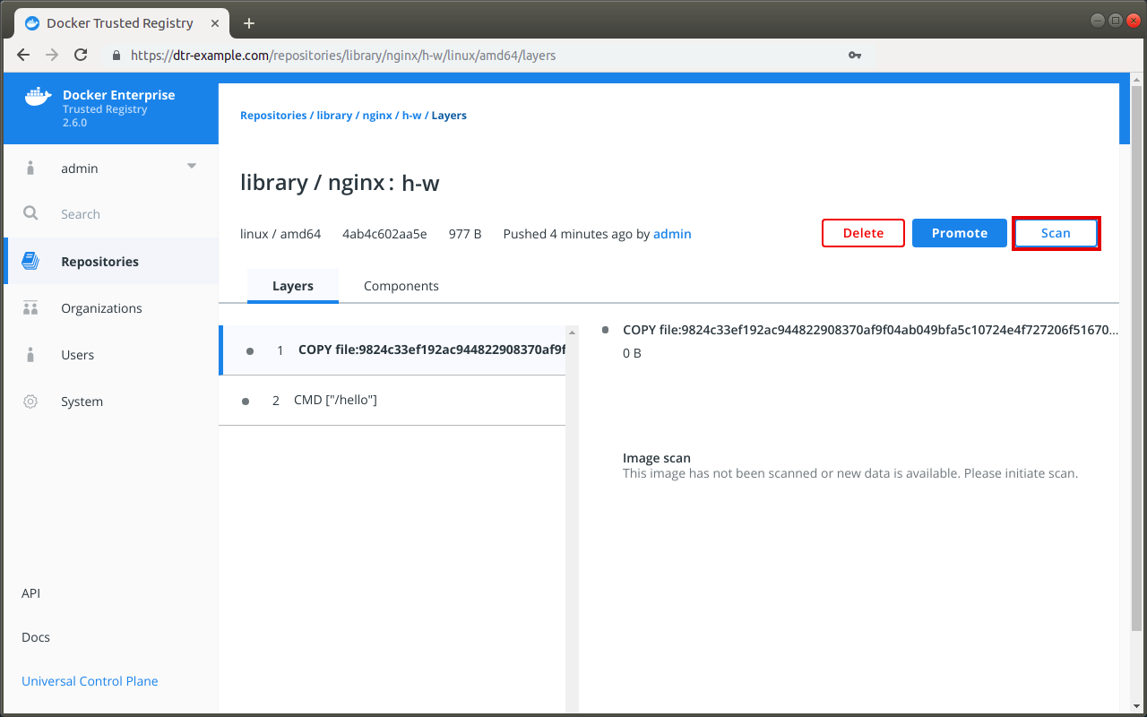
MSR begins the scanning process. You will need to refresh the page to see the results once the scan is complete.
Change the scanning mode
You can change the scanning mode for each individual repository at any time. You might want to disable scanning if you are pushing an image repeatedly during troubleshooting and don’t want to waste resources scanning and re-scanning, or if a repository contains legacy code that is not used or updated frequently.
Note
To change an individual repository’s scanning mode, you
must have write or administrator access to the repo.
To change the repository scanning mode:
Navigate to the repository, and click the Settings tab.
Scroll down to the Image scanning section.
Select the desired scanning mode.
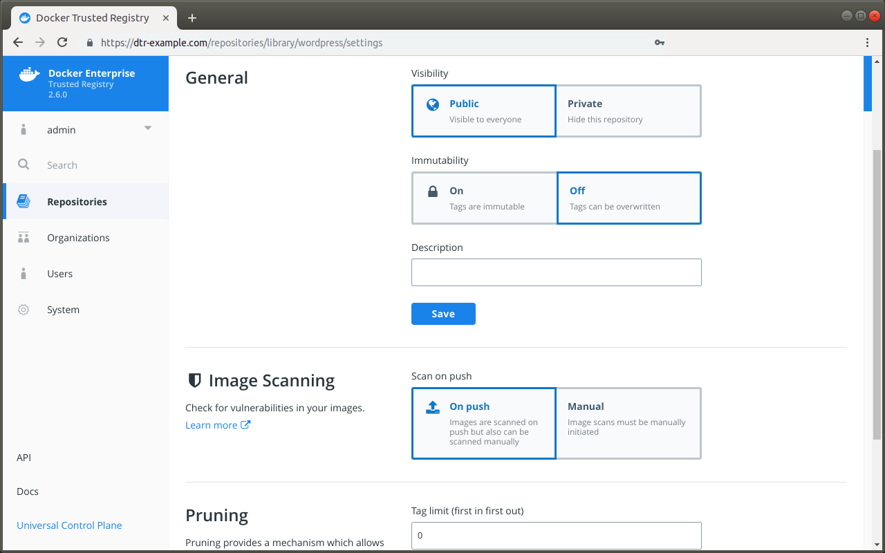
View security scan results
Once MSR has run a security scan for an image, you can view the results.
The Tags tab for each repository includes a summary of the most recent scan results for each image.
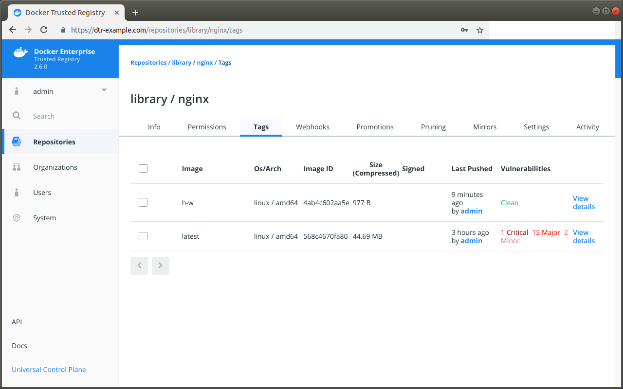
The text Clean in green indicates that the scan did not find any vulnerabilities.
A red or orange text indicates that vulnerabilities were found, and the number of vulnerabilities is included on that same line according to severity: Critical, Major, Minor.
If the vulnerability scan could not detect the version of a component, it reports the vulnerabilities for all versions of that component.
From the repository Tags tab, you can click View details for a specific tag to see the full scan results. The top of the page also includes metadata about the image, including the SHA, image size, last push date, user who initiated the push, the security scan summary, and the security scan progress.
The scan results for each image include two different modes so you can quickly view details about the image, its components, and any vulnerabilities found.
The Layers view lists the layers of the image in the order that they are built by Dockerfile.
This view can help you find exactly which command in the build introduced the vulnerabilities, and which components are associated with that single command. Click a layer to see a summary of its components. You can then click on a component to switch to the Component view and get more details about the specific item.
Note
The layers view can be long, so be sure to scroll down if you don’t immediately see the reported vulnerabilities.
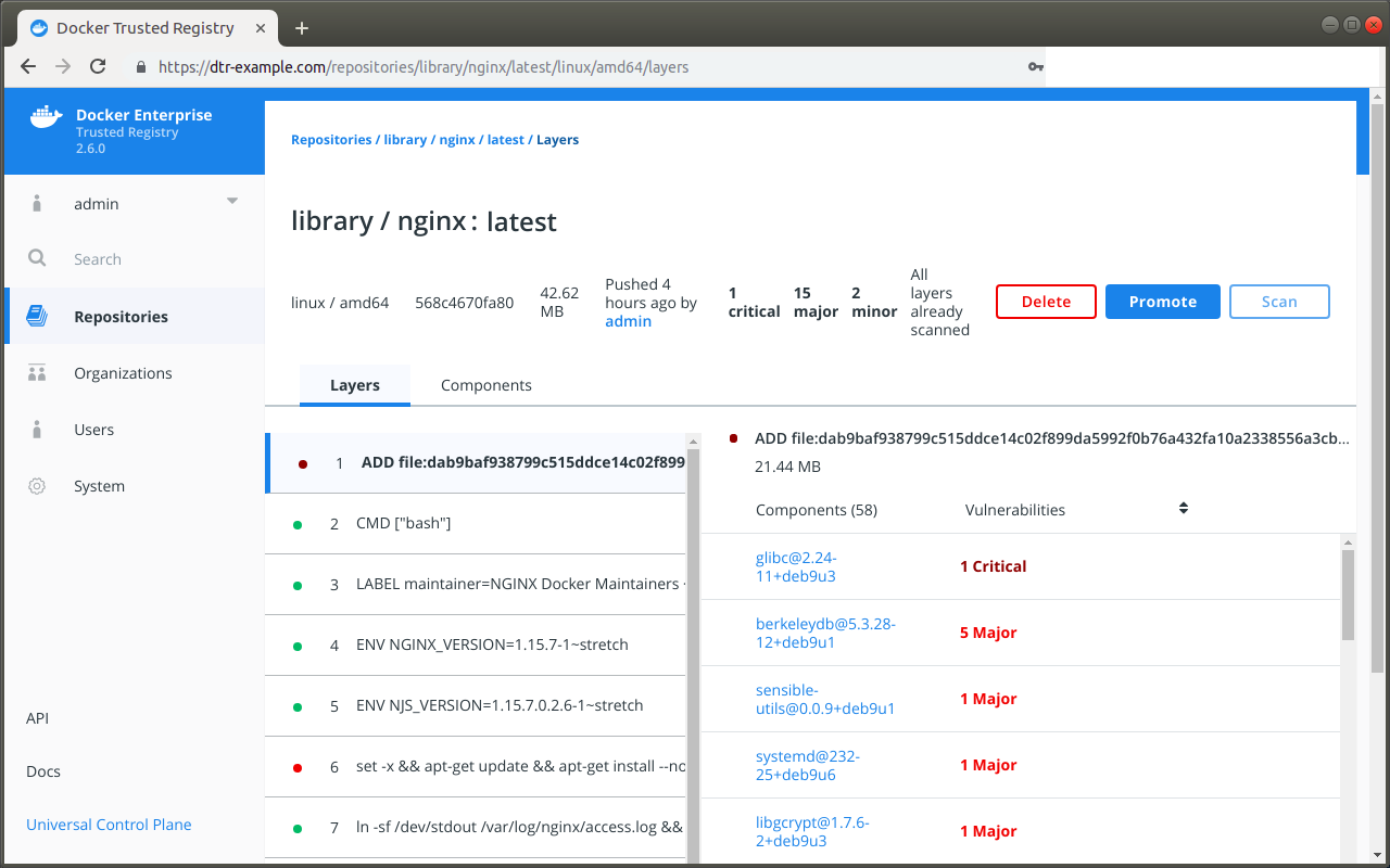
The Components view lists the individual component libraries indexed by the scanning system, in order of severity and number of vulnerabilities found, with the most vulnerable library listed first.
Click on an individual component to view details about the vulnerability it introduces, including a short summary and a link to the official CVE database report. A single component can have multiple vulnerabilities, and the scan report provides details on each one. The component details also include the license type used by the component, and the filepath to the component in the image.
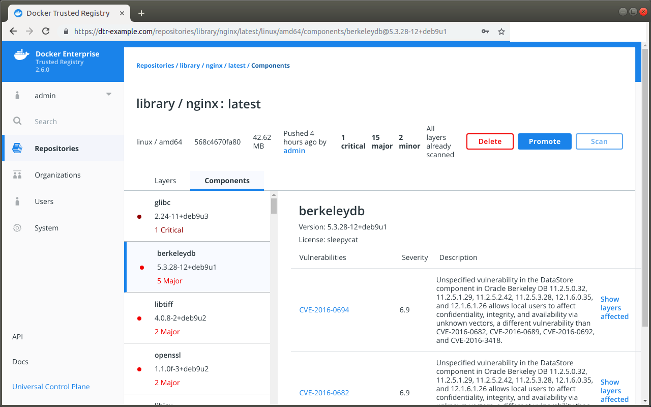
What to do next
If you find that an image in your registry contains vulnerable components, you can use the linked CVE scan information in each scan report to evaluate the vulnerability and decide what to do.
If you discover vulnerable components, you should check if there is an updated version available where the security vulnerability has been addressed. If necessary, you can contact the component’s maintainers to ensure that the vulnerability is being addressed in a future version or a patch update.
If the vulnerability is in a base layer (such as an operating
system) you might not be able to correct the issue in the image. In this
case, you can switch to a different version of the base layer, or you
can find an equivalent, less vulnerable base layer.
Address vulnerabilities in your repositories by updating the images to use updated and corrected versions of vulnerable components, or by using a different component offering the same functionality. When you have updated the source code, run a build to create a new image, tag the image, and push the updated image to your MSR instance. You can then re-scan the image to confirm that you have addressed the vulnerabilities.
Where to go next
Override a vulnerability
MSR scans images for vulnerabilities. At times, however, it may report image vulnerabilities that you know have been fixed, and whenever that happens the warning can be dismissed.
Access the MSR web interface.
Click Repositories in the left-hand menu, and locate the repository that has been scanned.
Click View details to review the image scan results, and select Components to see the vulnerabilities for each component packaged in the image.
Select the component with the vulnerability you want to ignore, navigate to the vulnerability, and click Hide.
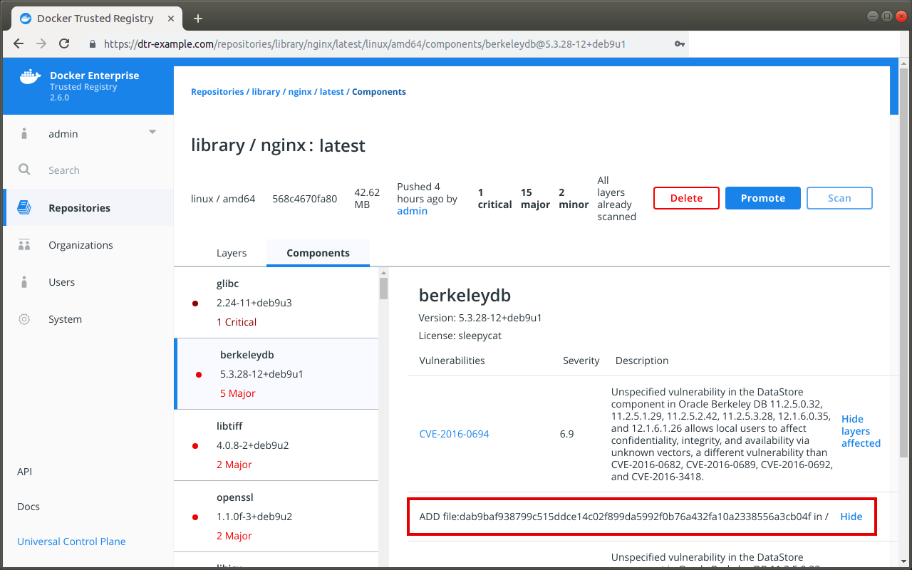
Once dismissed, the vulnerability is hidden system-wide and will no longer be reported as a vulnerability on affected images with the same layer IDs or digests. In addition, MSR will not reevaluate the promotion policies that have been set up for the repository.
If after hiding a particular vulnerability you want the promotion policy for the image to be reevaluated, click Promote.
Where to go next
Prevent tags from being overwritten
By default, users with read and write access to a repository can push the same tag
multiple times to that repository. For example, when user A pushes an image
to library/wordpress:latest, there is no preventing user B from pushing
an image with the same name but a completely different functionality. This can
make it difficult to trace the image back to the build that generated it.
To prevent tags from being overwritten, you can configure a repository to be immutable. Once configured, MSR will not allow anyone else to push another image tag with the same name.
Make tags immutable
You can enable tag immutability on a repository when you create it, or at any time after.
If you’re not already logged in, navigate to https://<msr-url> and
log in with your MKE credentials. To make tags immutable on a new
repository, do the following:
- Follow the steps in Create a repository.
- Click Show advanced settings, and turn on Immutability. Note that tag limits are enabled when immutability is enabled for a repository.
Select Repositories on the left navigation pane, and then click on the name of the repository that you want to view. Note that you will have to click on the repository name following the
/after the specific namespace for your repository.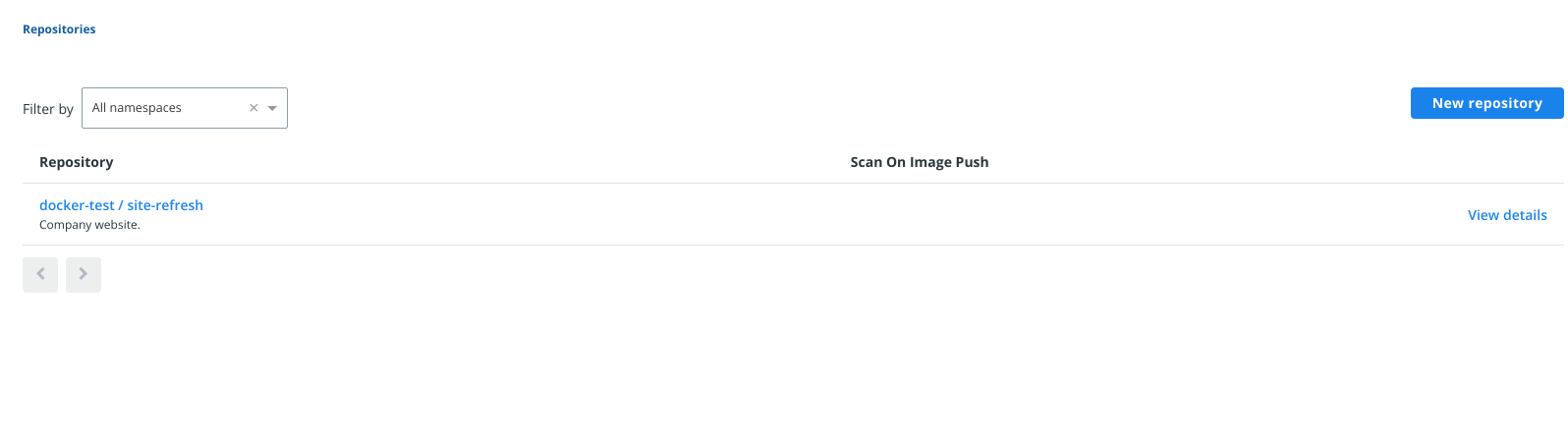
Select the Settings tab, and turn on Immutability.
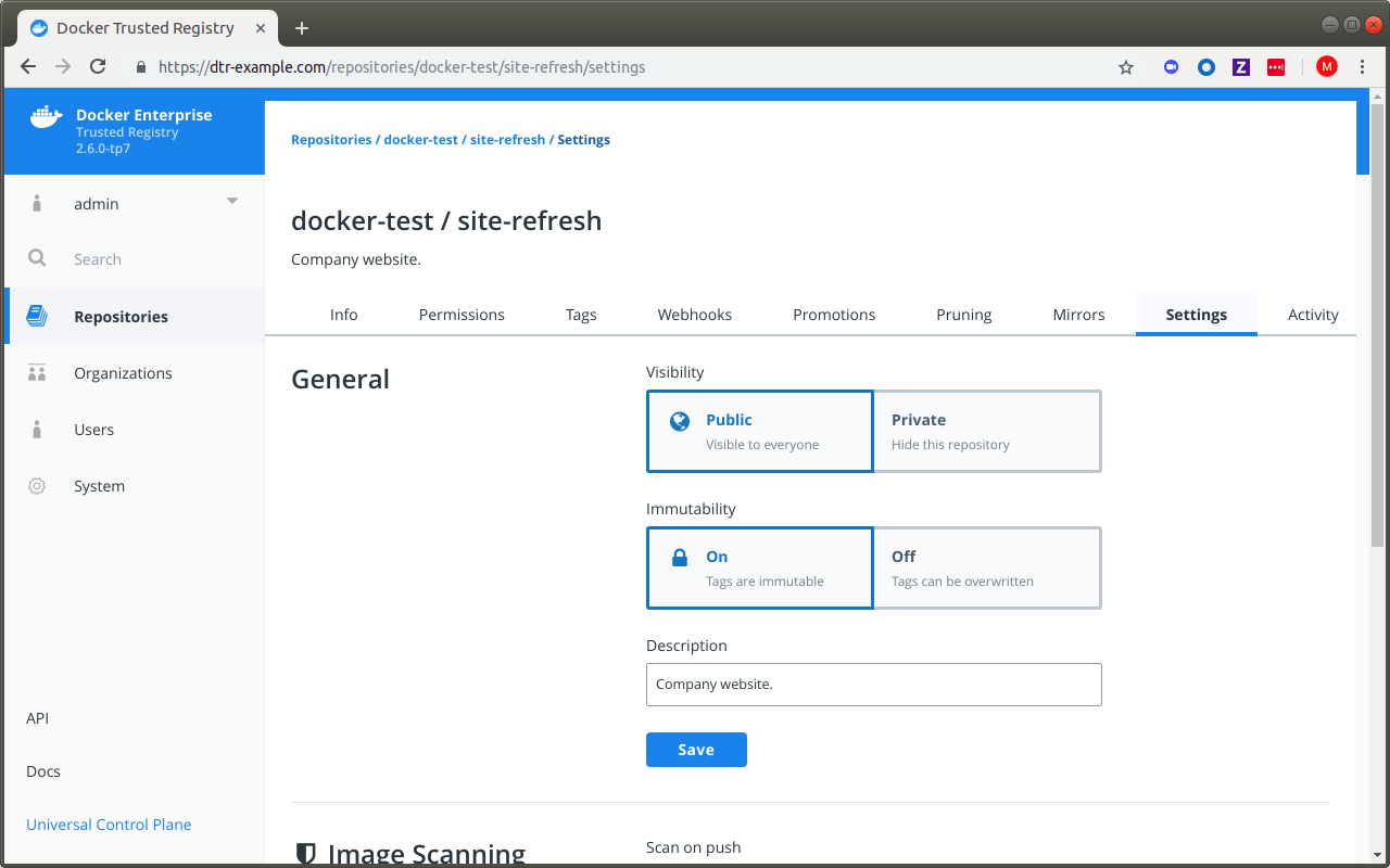
From now on, you will get an error message when trying to push a tag that already exists:
docker push dtr-example.com/library/wordpress:latest
unknown: tag=latest cannot be overwritten because
dtr-example.com/library/wordpress is an immutable repository
Where to go next
Sign images
Sign an image
Two key components of the Mirantis Secure Registry are the Notary Server and the Notary Signer. These two containers provide the required components for using Docker Content Trust (DCT) out of the box. Docker Content Trust allows you to sign image tags, therefore giving consumers a way to verify the integrity of your image.
As part of MSR, both the Notary and the Registry servers are accessed through a front-end proxy, with both components sharing the MKE’s RBAC (Role-based Access Control) Engine. Therefore, you do not need additional Docker client configuration in order to use DCT.
DCT is integrated with the Docker CLI, and allows you to:
- Configure repositories
- Add signers
- Sign images using the docker trust command

MKE has a feature which will prevent untrusted
images from being deployed on the cluster. To
use the feature, you need to sign and push images to your MSR. To tie the
signed images back to MKE, you need to sign the images with the private keys of
the MKE users. From a MKE client bundle, use key.pem as your private key,
and cert.pem as your public key on an x509 certificate.
To sign images in a way that MKE can trust, you need to:
- Download a client bundle for the user account you want to use for signing the images.
- Add the user’s private key to your machine’s trust store.
- Initialize trust metadata for the repository.
- Delegate signing for that repository to the MKE user.
- Sign the image.
The following example shows the nginx image getting pulled from
Docker Hub, tagged as dtr.example.com/dev/nginx:1, pushed to MSR,
and signed in a way that is trusted by MKE.
After downloading and extracting a MKE client bundle into your local
directory, you need to load the private key into the local Docker trust
store (~/.docker/trust). To illustrate the process, we will use
jeff as an example user.
$ docker trust key load --name jeff key.pem
Loading key from "key.pem"...
Enter passphrase for new jeff key with ID a453196:
Repeat passphrase for new jeff key with ID a453196:
Successfully imported key from key.pem
Next,initiate trust metadata for a MSR repository. If you have not
already done so, navigate to the MSR web UI, and create a repository
for your image. This example uses the nginx repository in the
prod namespace.
As part of initiating the repository, the public key of the MKE user needs to be added to the Notary server as a signer for the repository. You will be asked for a number of passphrases to protect the keys.Make a note of these passphrases.
$ docker trust signer add --key cert.pem jeff dtr.example.com/prod/nginx
Adding signer "jeff" to dtr.example.com/prod/nginx...
Initializing signed repository for dtr.example.com/prod/nginx...
Enter passphrase for root key with ID 4a72d81:
Enter passphrase for new repository key with ID e0d15a2:
Repeat passphrase for new repository key with ID e0d15a2:
Successfully initialized "dtr.example.com/prod/nginx"
Successfully added signer: jeff to dtr.example.com/prod/nginx
Inspect the trust metadata of the repository to make sure the user has been added correctly.
$ docker trust inspect --pretty dtr.example.com/prod/nginx
No signatures for dtr.example.com/prod/nginx
List of signers and their keys for dtr.example.com/prod/nginx
SIGNER KEYS
jeff 927f30366699
Administrative keys for dtr.example.com/prod/nginx
Repository Key: e0d15a24b7...540b4a2506b
Root Key: b74854cb27...a72fbdd7b9a
Finally, user jeff can sign an image tag. The following steps
include downloading the image from Hub, tagging the image for Jeff’s MSR
repository, pushing the image to Jeff’s MSR, as well as signing the tag
with Jeff’s keys.
$ docker pull nginx:latest
$ docker tag nginx:latest dtr.example.com/prod/nginx:1
$ docker trust sign dtr.example.com/prod/nginx:1
Signing and pushing trust data for local image dtr.example.com/prod/nginx:1, may overwrite remote trust data
The push refers to repository [dtr.example.com/prod/nginx]
6b5e2ed60418: Pushed
92c15149e23b: Pushed
0a07e81f5da3: Pushed
1: digest: sha256:5b49c8e2c890fbb0a35f6050ed3c5109c5bb47b9e774264f4f3aa85bb69e2033 size: 948
Signing and pushing trust metadata
Enter passphrase for jeff key with ID 927f303:
Successfully signed dtr.example.com/prod/nginx:1
Inspect the trust metadata again to make sure the image tag has been signed successfully.
$ docker trust inspect --pretty dtr.example.com/prod/nginx:1
Signatures for dtr.example.com/prod/nginx:1
SIGNED TAG DIGEST SIGNERS
1 5b49c8e2c8...90fbb2033 jeff
List of signers and their keys for dtr.example.com/prod/nginx:1
SIGNER KEYS
jeff 927f30366699
Administrative keys for dtr.example.com/prod/nginx:1
Repository Key: e0d15a24b74...96540b4a2506b
Root Key: b74854cb27c...1ea72fbdd7b9a
Alternatively, you can review the signed image from the MSR web UI.
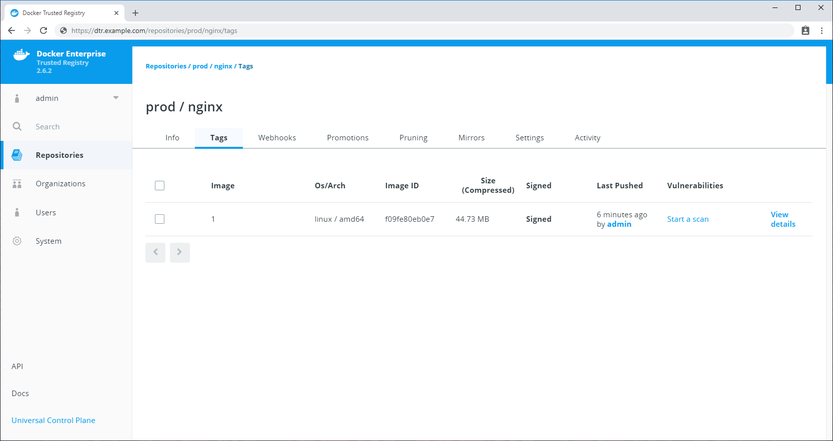
You have the option to sign an image using multiple MKE users’ keys. For
example, an image needs to be signed by a member of the Security
team and a member of the Developers team. Let’s assume jeff is a
member of the Developers team. In this case, we only need to add a
member of the Security team.
To do so, first add the private key of the Security team member to the local Docker trust store.
$ docker trust key load --name ian key.pem
Loading key from "key.pem"...
Enter passphrase for new ian key with ID 5ac7d9a:
Repeat passphrase for new ian key with ID 5ac7d9a:
Successfully imported key from key.pem
Upload the user’s public key to the Notary Server and sign the image.
You will be asked for jeff, the developer’s passphrase, as well as
the ian user’s passphrase to sign the tag.
$ docker trust signer add --key cert.pem ian dtr.example.com/prod/nginx
Adding signer "ian" to dtr.example.com/prod/nginx...
Enter passphrase for repository key with ID e0d15a2:
Successfully added signer: ian to dtr.example.com/prod/nginx
$ docker trust sign dtr.example.com/prod/nginx:1
Signing and pushing trust metadata for dtr.example.com/prod/nginx:1
Existing signatures for tag 1 digest 5b49c8e2c890fbb0a35f6050ed3c5109c5bb47b9e774264f4f3aa85bb69e2033 from:
jeff
Enter passphrase for jeff key with ID 927f303:
Enter passphrase for ian key with ID 5ac7d9a:
Successfully signed dtr.example.com/prod/nginx:1
Finally, check the tag again to make sure it includes two signers.
$ docker trust inspect --pretty dtr.example.com/prod/nginx:1
Signatures for dtr.example.com/prod/nginx:1
SIGNED TAG DIGEST SIGNERS
1 5b49c8e2c89...5bb69e2033 jeff, ian
List of signers and their keys for dtr.example.com/prod/nginx:1
SIGNER KEYS
jeff 927f30366699
ian 5ac7d9af7222
Administrative keys for dtr.example.com/prod/nginx:1
Repository Key: e0d15a24b741ab049470298734397afbea539400510cb30d3b996540b4a2506b
Root Key: b74854cb27cc25220ede4b08028967d1c6e297a759a6939dfef1ea72fbdd7b9a
If an administrator wants to delete a MSR repository that contains trust metadata, they will be prompted to delete the trust metadata first before removing the repository.
To delete trust metadata, you need to use the Notary CLI.
$ notary delete dtr.example.com/prod/nginx --remote
Deleting trust data for repository dtr.example.com/prod/nginx
Enter username: admin
Enter password:
Successfully deleted local and remote trust data for repository dtr.example.com/prod/nginx
If you don’t include the --remote flag, Notary deletes local cached
content but will not delete data from the Notary server.
Using Docker Content Trust with a Remote MKE Cluster
For more advanced deployments, you may want to share one Mirantis Secure Registry across multiple Mirantis Kubernetes Engines. However, customers wanting to adopt this model alongside the Only Run Signed Images MKE feature, run into problems as each MKE operates an independent set of users.
Docker Content Trust (DCT) gets around this problem, since users from a remote MKE are able to sign images in the central MSR and still apply runtime enforcement.
In the following example, we will connect MSR managed by MKE cluster 1 with a remote MKE cluster which we are calling MKE cluster 2, sign the image with a user from MKE cluster 2, and provide runtime enforcement within MKE cluster 2. This process could be repeated over and over, integrating MSR with multiple remote MKE clusters, signing the image with users from each environment, and then providing runtime enforcement in each remote MKE cluster separately.
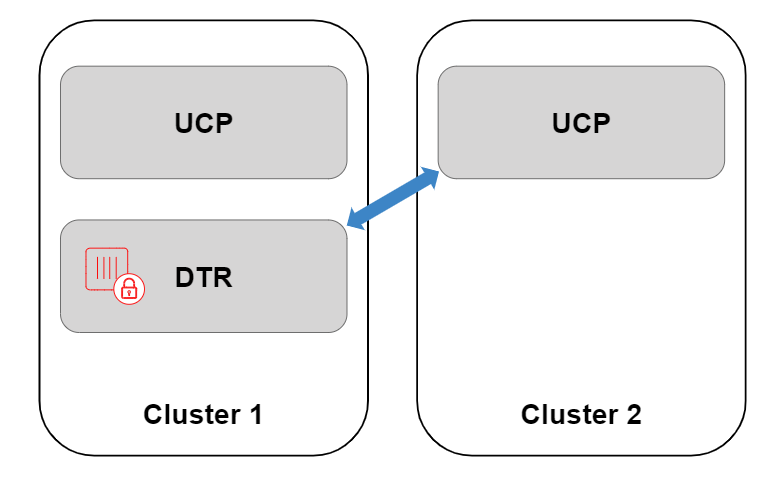
Note
Before attempting this guide, familiarize yourself with Docker Content Trust and Only Run Signed Images on a single MKE. Many of the concepts within this guide may be new without that background.
- Cluster 1, running MKE 3.0.x or higher, with a DTR 2.5.x or higher deployed within the cluster.
- Cluster 2, running MKE 3.0.x or higher, with no MSR node.
- Nodes on Cluster 2 need to trust the Certificate Authority which
signed MSR’s TLS Certificate. This can be tested by logging on to a
cluster 2 virtual machine and running
curl https://dtr.example.com. - The MSR TLS Certificate needs be properly configured, ensuring that the Loadbalancer/Public Address field has been configured, with this address included within the certificate.
- A machine with the Docker Client (CE 17.12 / EE 1803 or newer) installed, as this contains the relevant docker trust commands.
As there is no registry running within cluster 2, by default MKE will not know where to check for trust data. Therefore, the first thing we need to do is register MSR within the remote MKE in cluster 2. When you normally install MSR, this registration process happens by default to a local MKE, or cluster 1.
Note
The registration process allows the remote MKE to get signature data from MSR, however this will not provide Single Sign On (SSO). Users on cluster 2 will not be synced with cluster 1’s MKE or MSR. Therefore when pulling images, registry authentication will still need to be passed as part of the service definition if the repository is private. See the Kubernetes example.
To add a new registry, retrieve the Certificate Authority (CA) used to
sign the MSR TLS Certificate through the MSR URL’s /ca endpoint.
$ curl -ks https://dtr.example.com/ca > dtr.crt
Next, convert the MSR certificate into a JSON configuration file for registration within the MKE for cluster 2.
You can find a template of the dtr-bundle.json below. Replace the
host address with your MSR URL, and enter the contents of the MSR CA
certificate between the new line commands \n and \n.
Note
JSON Formatting
Ensure there are no line breaks between each line of the MSR CA certificate within the JSON file. Use your favorite JSON formatter for validation.
$ cat dtr-bundle.json
{
"hostAddress": "dtr.example.com",
"caBundle": "-----BEGIN CERTIFICATE-----\n<contents of cert>\n-----END CERTIFICATE-----"
}
Now upload the configuration file to cluster 2’s MKE through the MKE API
endpoint, /api/config/trustedregistry_. To authenticate against the
API of cluster 2’s MKE, we have downloaded a MKE client
bundle,
extracted it in the current directory, and will reference the keys for
authentication.
$ curl --cacert ca.pem --cert cert.pem --key key.pem \
-X POST \
-H "Accept: application/json" \
-H "Content-Type: application/json" \
-d @dtr-bundle.json \
https://cluster2.example.com/api/config/trustedregistry_
Navigate to the MKE web interface to verify that the JSON file was imported successfully, as the MKE endpoint will not output anything. Select Admin > Admin Settings > Mirantis Secure Registry. If the registry has been added successfully, you should see the MSR listed.
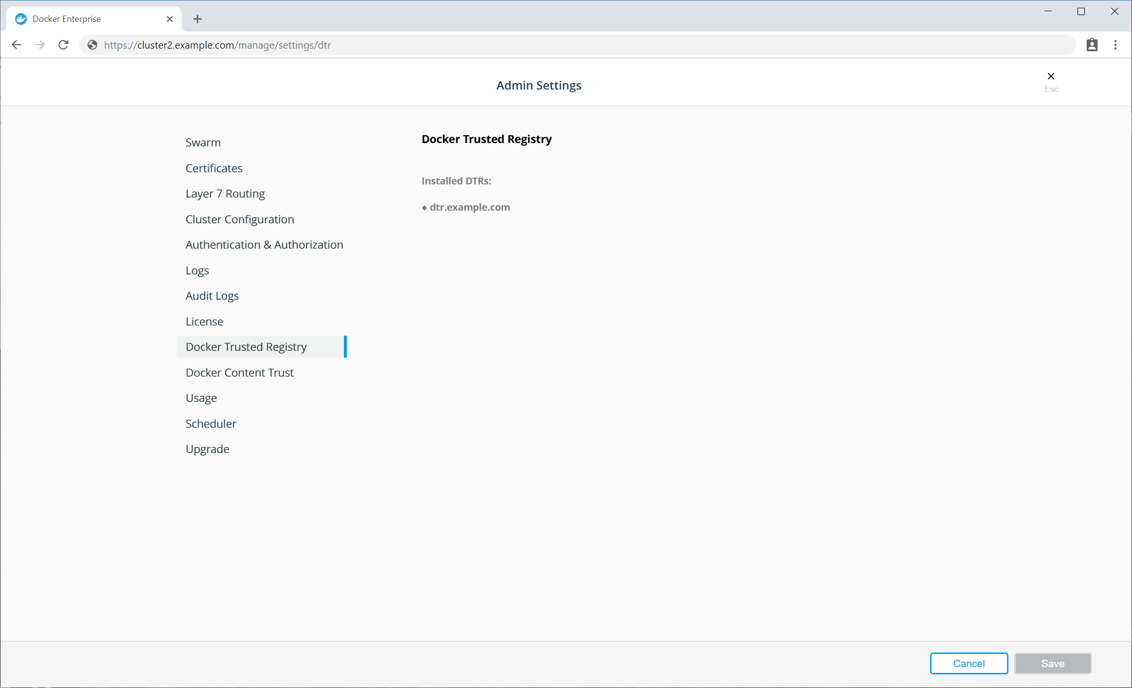
Additionally, you can check the full configuration
file within cluster 2’s MKE. Once downloaded, the
ucp-config.toml file should now contain a section called [registries]
$ curl --cacert ca.pem --cert cert.pem --key key.pem https://cluster2.example.com/api/ucp/config-toml > ucp-config.toml
If the new registry isn’t shown in the list, check the
ucp-controller container logs on cluster 2.
We will now sign an image and push this to MSR. To sign images we need a
user’s public private key pair from cluster 2. It can be found in a
client bundle, with key.pem being a private key and cert.pem
being the public key on an X.509 certificate.
First, load the private key into the local Docker trust store
(~/.docker/trust). The name used here is purely metadata to help
keep track of which keys you have imported.
$ docker trust key load --name cluster2admin key.pem
Loading key from "key.pem"...
Enter passphrase for new cluster2admin key with ID a453196:
Repeat passphrase for new cluster2admin key with ID a453196:
Successfully imported key from key.pem
Next initiate the repository, and add the public key of cluster 2’s user as a signer. You will be asked for a number of passphrases to protect the keys. Keep note of these passphrases, and see [Docker Content Trust documentation] (/engine/security/trust/trust_delegation/#managing-delegations-in-a-notary-server) to learn more about managing keys.
$ docker trust signer add --key cert.pem cluster2admin dtr.example.com/admin/trustdemo
Adding signer "cluster2admin" to dtr.example.com/admin/trustdemo...
Initializing signed repository for dtr.example.com/admin/trustdemo...
Enter passphrase for root key with ID 4a72d81:
Enter passphrase for new repository key with ID dd4460f:
Repeat passphrase for new repository key with ID dd4460f:
Successfully initialized "dtr.example.com/admin/trustdemo"
Successfully added signer: cluster2admin to dtr.example.com/admin/trustdemo
Finally, sign the image tag. This pushes the image up to MSR, as well as signs the tag with the user from cluster 2’s keys.
$ docker trust sign dtr.example.com/admin/trustdemo:1
Signing and pushing trust data for local image dtr.example.com/admin/trustdemo:1, may overwrite remote trust data
The push refers to repository [dtr.olly.dtcntr.net/admin/trustdemo]
27c0b07c1b33: Layer already exists
aa84c03b5202: Layer already exists
5f6acae4a5eb: Layer already exists
df64d3292fd6: Layer already exists
1: digest: sha256:37062e8984d3b8fde253eba1832bfb4367c51d9f05da8e581bd1296fc3fbf65f size: 1153
Signing and pushing trust metadata
Enter passphrase for cluster2admin key with ID a453196:
Successfully signed dtr.example.com/admin/trustdemo:1
Within the MSR web interface, you should now be able to see your newly pushed tag with the Signed text next to the size.
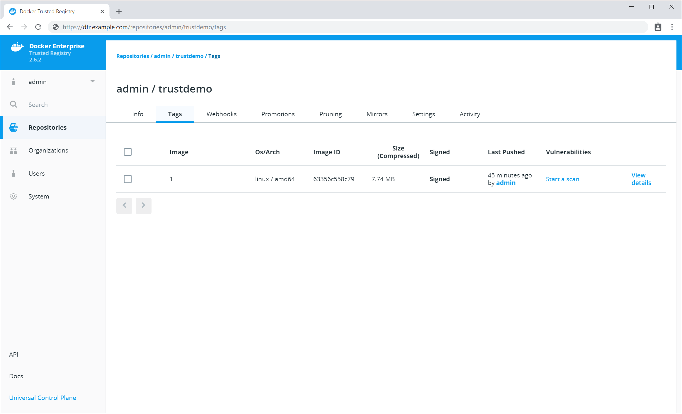
You could sign this image multiple times if required, whether it’s multiple teams from the same cluster wanting to sign the image, or you integrating MSR with more remote MKEs so users from clusters 1, 2, 3, or more can all sign the same image.
We can now enable Only Run Signed Images on the remote MKE. To do this, login to cluster 2’s MKE web interface as an admin. Select Admin > Admin Settings > Docker Content Trust.
See Run only the images you trust for more information on only running signed images in MKE.
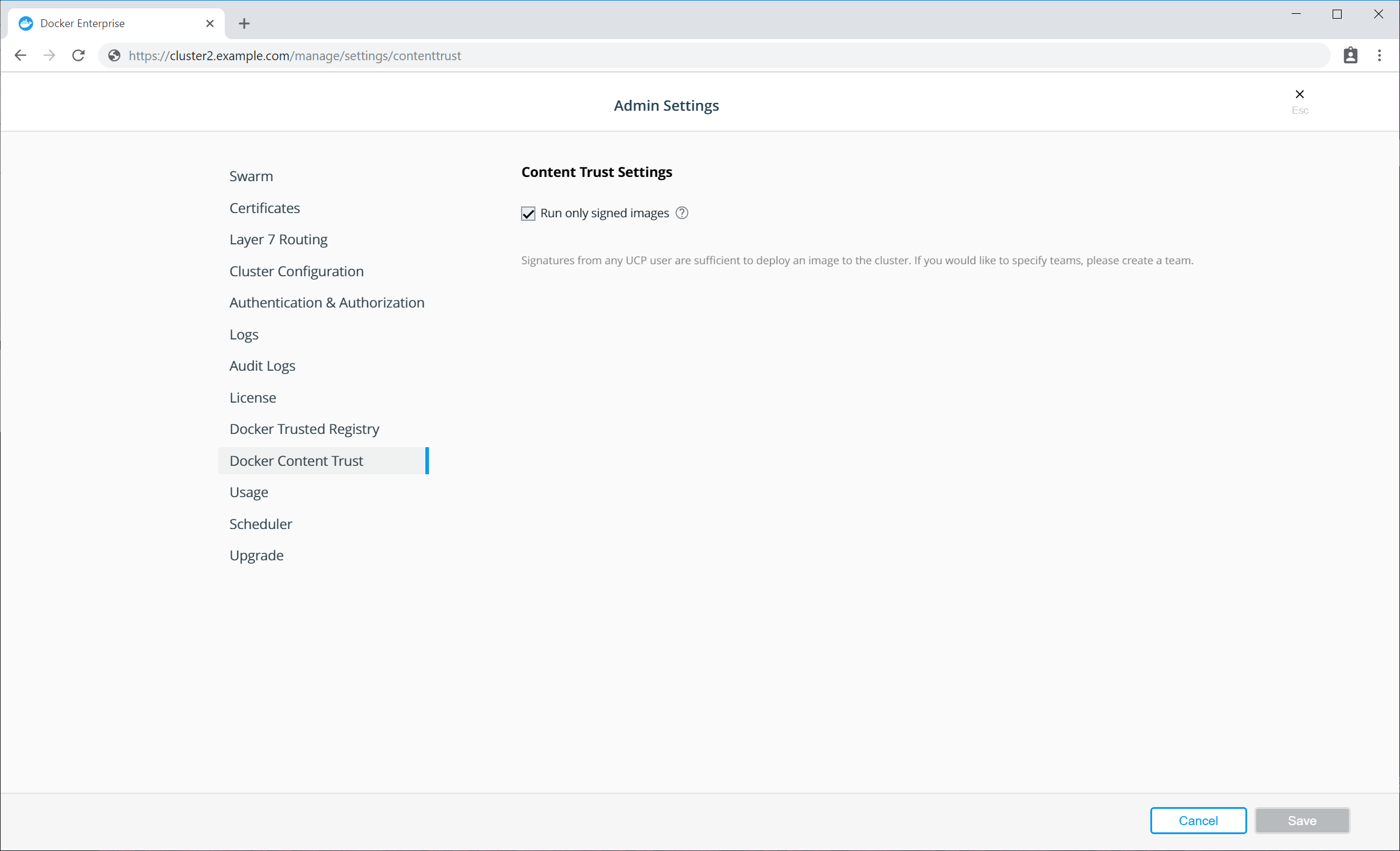
Finally we can now deploy a workload on cluster 2, using a signed image
from a MSR running on cluster 1. This workload could be a simple
$ docker run, a Swarm Service, or a Kubernetes workload. As a simple
test, source a client bundle, and try running one of your signed images.
$ source env.sh
$ docker service create dtr.example.com/admin/trustdemo:1
nqsph0n6lv9uzod4lapx0gwok
overall progress: 1 out of 1 tasks
1/1: running [==================================================>]
verify: Service converged
$ docker service ls
ID NAME MODE REPLICAS IMAGE PORTS
nqsph0n6lv9u laughing_lamarr replicated 1/1 dtr.example.com/admin/trustdemo:1
If the image is stored in a private repository within MSR, you need to pass credentials to the Orchestrator as there is no SSO between cluster 2 and MSR. See the relevant Kubernetes documentation for more details.
image or trust data does not exist for dtr.example.com/admin/trustdemo:1
This means something went wrong when initiating the repository or signing the image, as the tag contains no signing data.
Error response from daemon: image did not meet required signing policy
dtr.example.com/admin/trustdemo:1: image did not meet required signing policy
This means that the image was signed correctly, however the user who signed the image does not meet the signing policy in cluster 2. This could be because you signed the image with the wrong user keys.
Error response from daemon: dtr.example.com must be a registered trusted registry. See 'docker run --help'.
This means you have not registered MSR to work with a remote MKE instance yet, as outlined in Registering MSR with a remote Mirantis Kubernetes Engine.
Promotion policies and monitoring
Promotion policies overview
Mirantis Secure Registry allows you to automatically promote and mirror images based on a policy. In MSR 2.7, you have the option to promote applications with the experimental docker app CLI addition. Note that scanning-based promotion policies do not take effect until all application-bundled images have been scanned. This way you can create a Docker-centric development pipeline.
You can mix and match promotion policies, mirroring policies, and webhooks to create flexible development pipelines that integrate with your existing CI/CD systems.
Promote an image using policies
One way to create a promotion pipeline is to automatically promote images to another repository.
You start by defining a promotion policy that’s specific to a repository. When someone pushes an image to that repository, MSR checks if it complies with the policy you set up and automatically pushes the image to another repository.

Learn how to promote an image using policies.
Mirror images to another registry
You can also promote images between different MSR deployments. This not only allows you to create promotion policies that span multiple MSRs, but also allows you to mirror images for security and high availability.

You start by configuring a repository with a mirroring policy. When someone pushes an image to that repository, MSR checks if the policy is met, and if so pushes it to another MSR deployment or Docker Hub.
Learn how to mirror images to another registry.
Mirror images from another registry
Another option is to mirror images from another MSR deployment. You configure a repository to poll for changes in a remote repository. All new images pushed into the remote repository are then pulled into MSR.

This is an easy way to configure a mirror for high availability since you won’t need to change firewall rules that are in place for your environments.
Promote an image using policies
Mirantis Secure Registry allows you to create image promotion pipelines based on policies.
In this example we will create an image promotion pipeline such that:
- Developers iterate and push their builds to the
dev/websiterepository. - When the team creates a stable build, they make sure their image is
tagged with
-stable. - When a stable build is pushed to the
dev/websiterepository, it will automatically be promoted toqa/websiteso that the QA team can start testing.
With this promotion policy, the development team doesn’t need access to the QA repositories, and the QA team doesn’t need access to the development repositories.
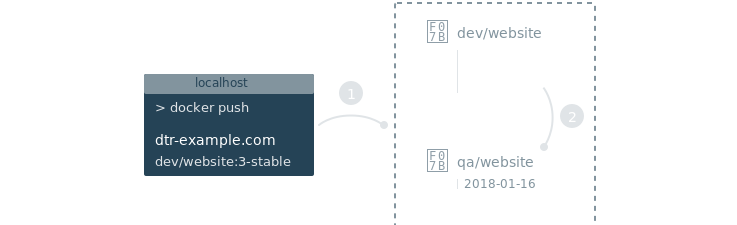
Configure your repository
Once you’ve Create a repository, navigate to the repository page on the MSR web interface, and select the Promotions tab.
Note
Only administrators can globally create and edit promotion policies. By default users can only create and edit promotion policies on repositories within their user namespace. For more information on user permissions, see Authentication and Authorization.
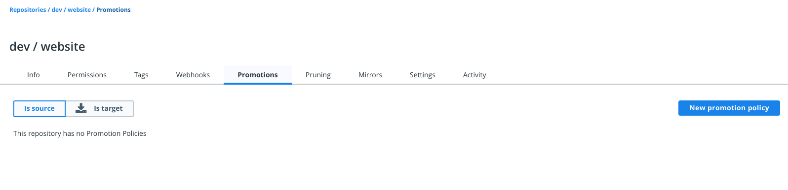
Click New promotion policy, and define the image promotion criteria.
MSR allows you to set your promotion policy based on the following image attributes:
| Name | Description | Example |
|---|---|---|
| Tag name | Whether the tag name equals, starts with, ends with, contains, is one of, or is not one of your specified string values | Promote to Target if Tag name ends in stable |
| Component | Whether the image has a given component and the component name equals, starts with, ends with, contains, is one of, or is not one of your specified string values | Promote to Target if Component name starts with b |
| Vulnarabilities | Whether the image has vulnerabilities – critical, major, minor, or all – and your selected vulnerability filter is greater than or equals, greater than, equals, not equals, less than or equals, or less than your specified number | Promote to Target if Critical vulnerabilities = 3 |
| License | Whether the image uses an intellectual property license and is one of or not one of your specified words | Promote to Target if License name = docker |
Now you need to choose what happens to an image that meets all the criteria.
Select the target organization or namespace and repository where the image is going to be pushed. You can choose to keep the image tag, or transform the tag into something more meaningful in the destination repository, by using a tag template.
In this example, if an image in the dev/website is tagged with a
word that ends in “stable”, MSR will automatically push that image to
the qa/website repository. In the destination repository the image
will be tagged with the timestamp of when the image was promoted.
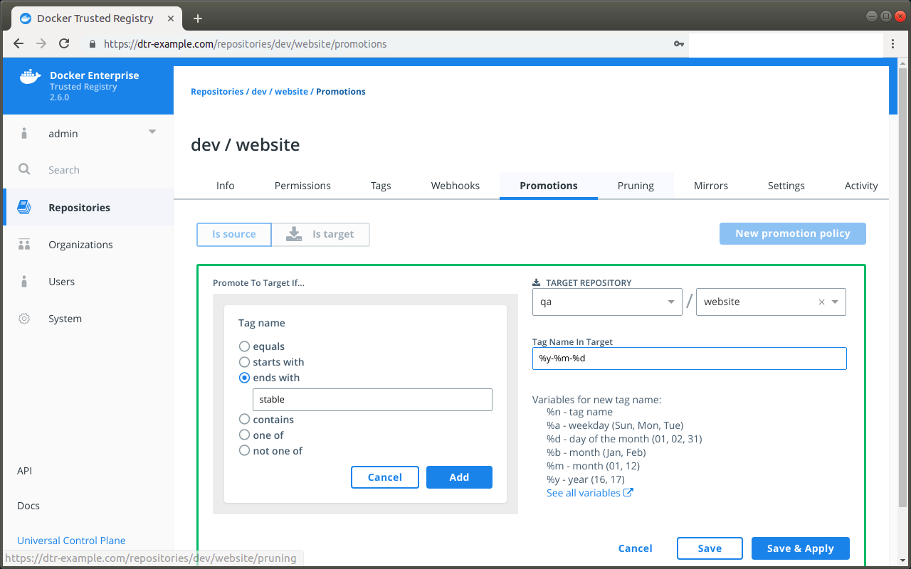
Everything is set up! Once the development team pushes an image that
complies with the policy, it automatically gets promoted. To confirm,
select the Promotions tab on the dev/website repository.
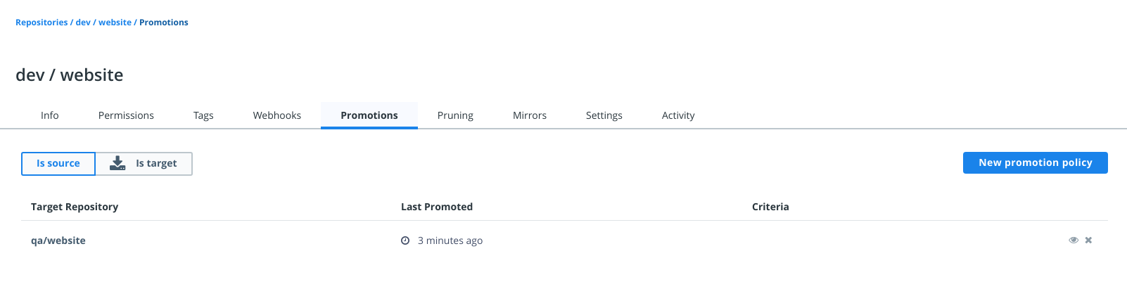
You can also review the newly pushed tag in the target repository by
navigating to qa/website and selecting the Tags tab.
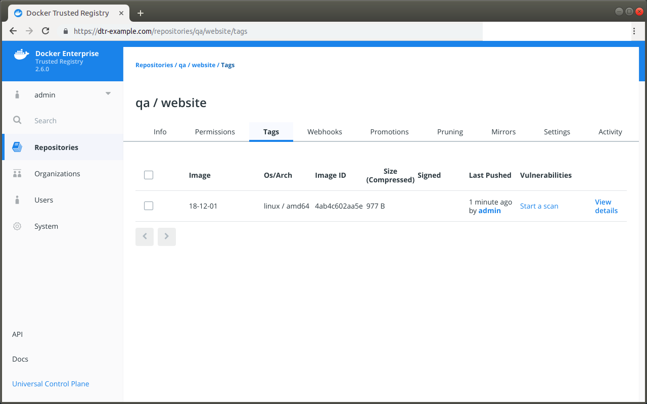
Where to go next
Mirror images to another registry
Mirantis Secure Registry allows you to create mirroring policies for a repository. When an image gets pushed to a repository and meets the mirroring criteria, MSR automatically pushes it to a repository in a remote Mirantis Secure Registry or Hub registry.
This not only allows you to mirror images but also allows you to create image promotion pipelines that span multiple MSR deployments and datacenters.
In this example we will create an image mirroring policy such that:
- Developers iterate and push their builds to
dtr-example.com/dev/websitethe repository in the MSR deployment dedicated to development. - When the team creates a stable build, they make sure their image is
tagged with
-stable. - When a stable build is pushed to
dtr-example.com/dev/website, it will automatically be pushed toqa-example.com/qa/website, mirroring the image and promoting it to the next stage of development.
With this mirroring policy, the development team does not need access to the QA cluster, and the QA team does not need access to the development cluster.
You need to have permissions to push to the destination repository in order to set up the mirroring policy.
Configure your repository connection
Once you have Create a repository, navigate to the repository page on the web interface, and select the Mirrors tab.
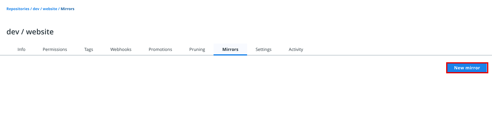
Click New mirror to define where the image will be pushed if it meets the mirroring criteria.
Under Mirror direction, choose Push to remote registry. Specify the following details:
| Field | Description |
|---|---|
| Registry type | You can choose between Mirantis Secure Registry and
Docker Hub. If you choose MSR, enter your MSR URL.
Otherwise, Docker Hub defaults to
https://index.docker.io |
| Username and password or access token | Your credentials in the remote repository you wish to push to. To use an access token instead of your password, see authentication token. |
| Repository | Enter the namespace and the repository_name after the / |
| Show advanced settings | Enter the TLS details for the remote repository or check
Skip TLS verification. If the MSR remote repository is
using self-signed TLS certificates or certificates signed by your own
certificate authority, you also need to provide the public key
certificate for that CA. You can retrieve the certificate by accessing
https://<msr-domain>/ca. Remote certificate authority
is optional for a remote repository in Docker Hub. |
Note
Make sure the account you use for the integration has permissions to write to the remote repository.
Click Connect to test the integration.
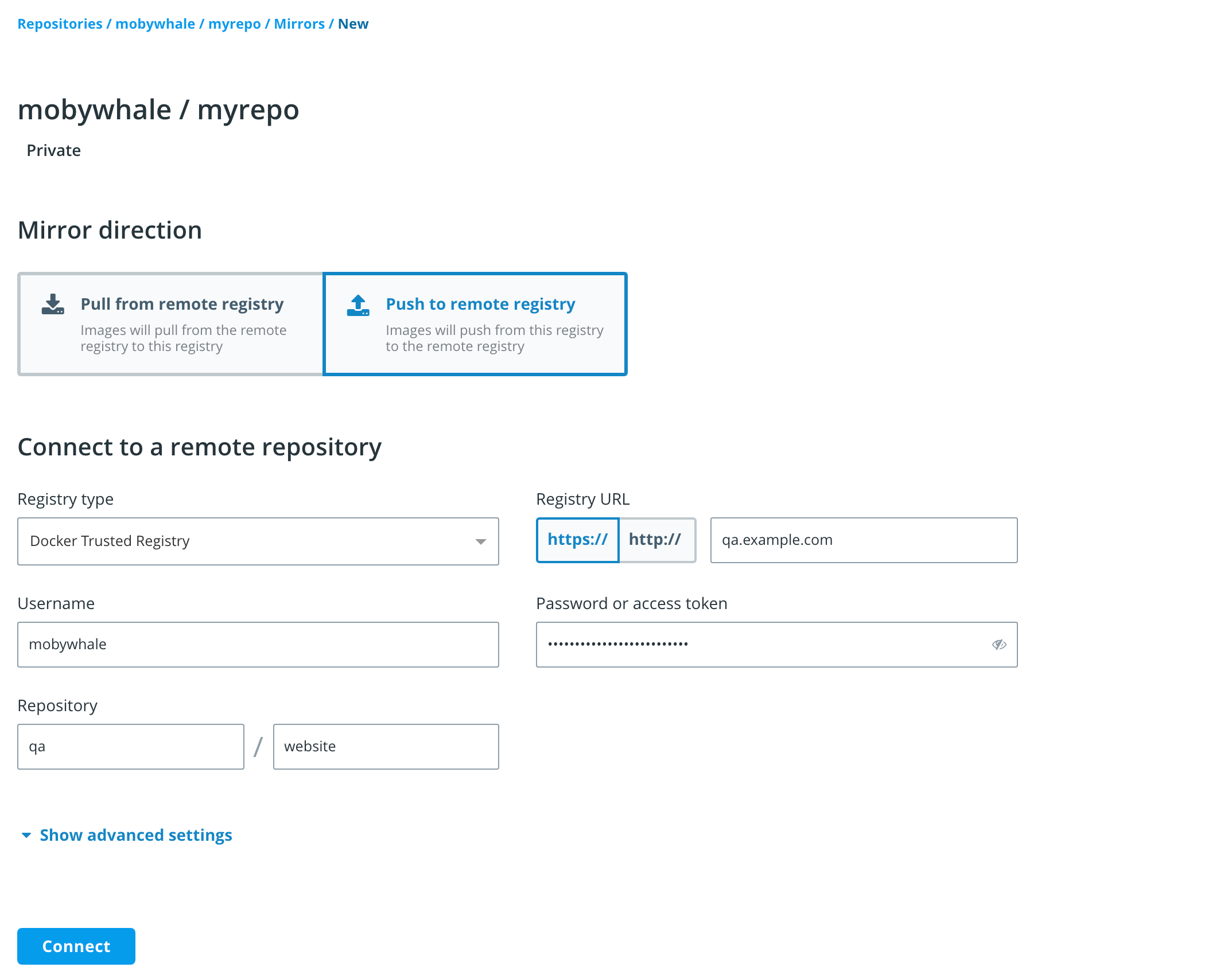
In this example, the image gets pushed to the qa/example repository
of a MSR deployment available at qa-example.com using a service
account that was created just for mirroring images between repositories.
Next, set your push triggers. MSR allows you to set your mirroring policy based on the following image attributes:
| Name | Description | Example |
|---|---|---|
| Tag name | Whether the tag name equals, starts with, ends with, contains, is one of, or is not one of your specified string values | Copy image to remote repository if Tag name ends in stable |
| Component | Whether the image has a given component and the component name equals, starts with, ends with, contains, is one of, or is not one of your specified string values | Copy image to remote repository if Component name starts with b |
| Vulnarabilities | Whether the image has vulnerabilities – critical, major, minor, or all – and your selected vulnerability filter is greater than or equals, greater than, equals, not equals, less than or equals, or less than your specified number | Copy image to remote repository if Critical vulnerabilities = 3 |
| License | Whether the image uses an intellectual property license and is one of or not one of your specified words | Copy image to remote repository if License name = docker |
You can choose to keep the image tag, or transform the tag into something more meaningful in the remote registry by using a tag template.
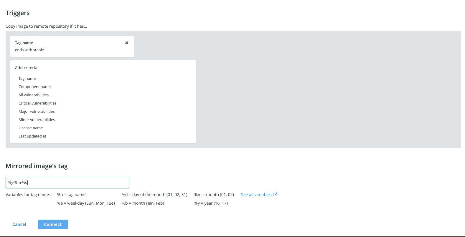
In this example, if an image in the dev/website repository is tagged
with a word that ends in stable, MSR will automatically push that
image to the MSR deployment available at qa-example.com. The image
is pushed to the qa/example repository and is tagged with the
timestamp of when the image was promoted.
Everything is set up! Once the development team pushes an image that
complies with the policy, it automatically gets promoted to
qa/example in the remote trusted registry at qa-example.com.
Metadata persistence
When an image is pushed to another registry using a mirroring policy, scanning and signing data is not persisted in the destination repository.
If you have scanning enabled for the destination repository, MSR is going to scan the image pushed. If you want the image to be signed, you need to do it manually.
Where to go next
Mirror images from another registry
Mirantis Secure Registry allows you to set up a mirror of a repository by constantly polling it and pulling new image tags as they are pushed. This ensures your images are replicated across different registries for high availability. It also makes it easy to create a development pipeline that allows different users access to a certain image without giving them access to everything in the remote registry.

To mirror a repository, start by Create a repository in the MSR deployment that will serve as your mirror. Previously, you were only able to set up pull mirroring from the API. In addition, you can also mirror and pull from a remote MSR or Docker Hub repository.
Pull mirroring on the web interface
To get started, navigate to https://<msr-url> and log in with your
MKE credentials.
Select Repositories on the left navigation pane, and then click on
the name of the repository that you want to view. Note that you will
have to click on the repository name following the / after the
specific namespace for your repository.
Next, select the Mirrors tab and click New mirror. On the New mirror page, choose Pull from remote registry.
Specify the following details:
| Field | Description |
|---|---|
| Registry type | You can choose between Mirantis Secure Registry and
Docker Hub. If you choose MSR, enter your MSR URL.
Otherwise, Docker Hub defaults to
https://index.docker.io |
| Username and password or access token | Your credentials in the remote repository you wish to poll from. To use an access token instead of your password, see authentication token. |
| Repository | Enter the namespace and the repository_name after the / |
| Show advanced settings | Enter the TLS details for the remote repository or check
Skip TLS verification. If the MSR remote repository is using
self-signed certificates or certificates signed by your own certificate
authority, you also need to provide the public key certificate for that
CA. You can retrieve the certificate by accessing
https://<msr-domain>/ca. Remote certificate authority
is optional for a remote repository in Docker Hub. |
After you have filled out the details, click Connect to test the integration.
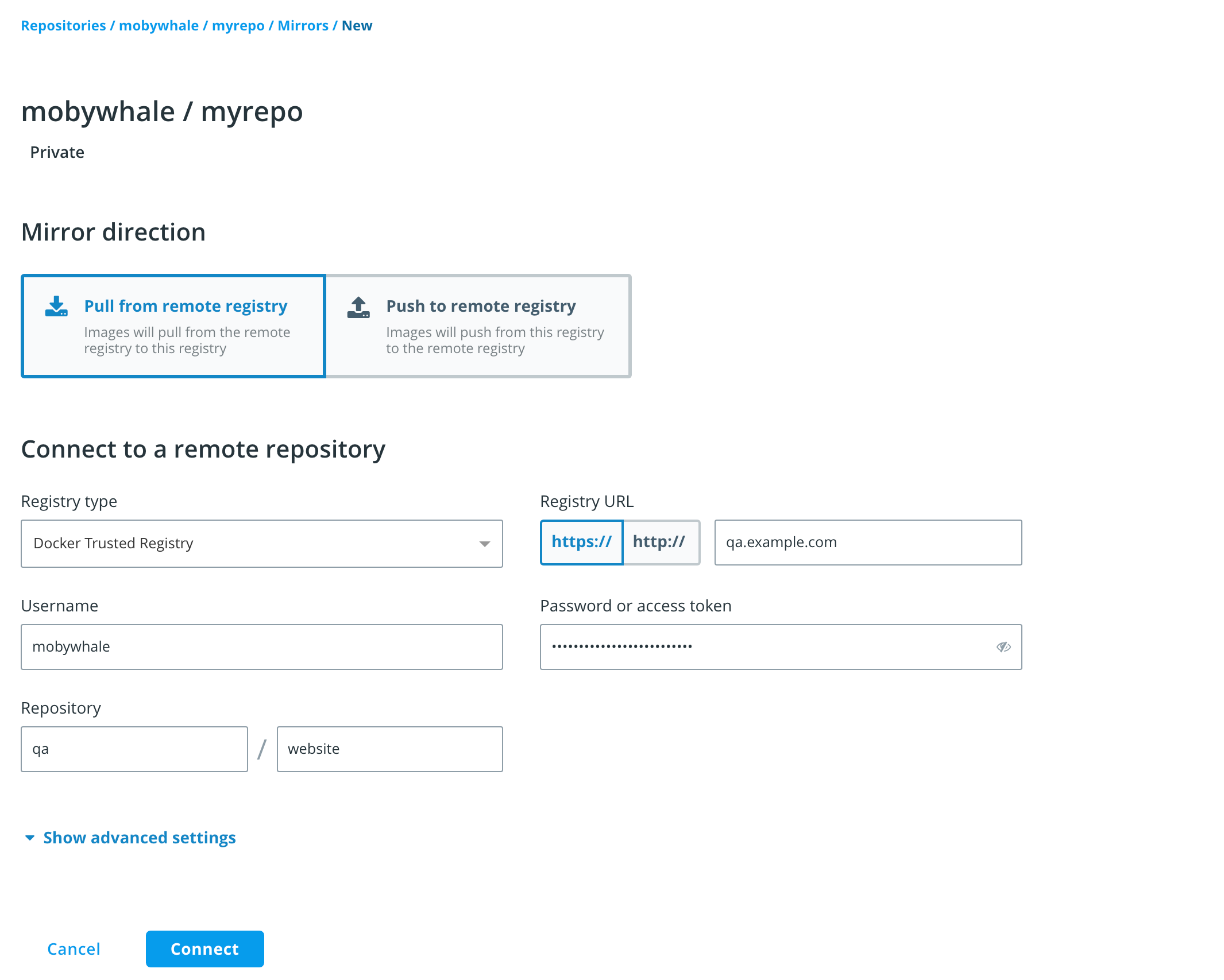
Once you have successfully connected to the remote repository, new buttons appear:
- Click Save to mirror future tag, or;
- To mirror all existing and future tags, click Save & Apply instead.
Pull mirroring on the API
There are a few different ways to send your MSR API requests. To explore the different API resources and endpoints from the web interface, click API on the bottom left navigation pane.
Search for the endpoint:
POST /api/v0/repositories/{namespace}/{reponame}/pollMirroringPolicies
Click Try it out and enter your HTTP request details.
namespace and reponame refer to the repository that will be poll
mirrored. The boolean field, initialEvaluation, corresponds to
Save when set to false and will only mirror images created
after your API request. Setting it to true corresponds to
Save & Apply which means all tags in the remote repository will
be evaluated and mirrored. The other body parameters correspond to the
relevant remote repository details that you can see on the MSR web
interface. As a best practice,
use a service account just for this purpose. Instead of providing the
password for that account, you should pass an authentication
token.
If the MSR remote repository is using self-signed certificates or
certificates signed by your own certificate authority, you also need to
provide the public key certificate for that CA. You can get it by
accessing https://<msr-domain>/ca. The remoteCA field is
optional for mirroring a Docker Hub repository.
Click Execute. On success, the API returns an HTTP 201
response.
Review the poll mirror job log
Once configured, the system polls for changes in the remote repository
and runs the poll_mirror job every 30 minutes. On success, the
system will pull in new images and mirror them in your local repository.
You can also filter for poll_mirror jobs to review
when it was last ran. To manually trigger the job and force pull
mirroring, use the POST /api/v0/jobs API endpoint and specify
poll_mirror as your action.
curl -X POST "https:/<msr-url>/api/v0/jobs" -H "accept: application/json" -H "content-type: application/json" -d "{ \"action\": \"poll_mirror\"}"
See Manage Jobs to learn more about job management within MSR.
Where to go next
Template reference
When defining promotion policies you can use templates to dynamically name the tag that is going to be created.
Important
Whenever an image promotion event occurs, the MSR timestamp for the event is in UTC (Coordinated Univeral Time). That timestamp, however, is converted by the browser and presents in the user’s time zone. Inversely, if a time-based tag is applied to a target image, MSR captures it in UTC but cannot convert it to the user’s timezone due to the tags being immutable strings.
You can use these template keywords to define your new tag:
| Template | Description | Example result |
|---|---|---|
%n |
The tag to promote | 1, 4.5, latest |
%A |
Day of the week | Sunday, Monday |
%a |
Day of the week, abbreviated | Sun, Mon, Tue |
%w |
Day of the week, as a number | 0, 1, 6 |
%d |
Number for the day of the month | 01, 15, 31 |
%B |
Month | January, December |
%b |
Month, abbreviated | Jan, Jun, Dec |
%m |
Month, as a number | 01, 06, 12 |
%Y |
Year | 1999, 2015, 2048 |
%y |
Year, two digits | 99, 15, 48 |
%H |
Hour, in 24 hour format | 00, 12, 23 |
%I |
Hour, in 12 hour format | 01, 10, 10 |
%p |
Period of the day | AM, PM |
%M |
Minute | 00, 10, 59 |
%S |
Second | 00, 10, 59 |
%f |
Microsecond | 000000, 999999 |
%Z |
Name for the timezone | UTC, PST, EST |
%j |
Day of the year | 001, 200, 366 |
%W |
Week of the year | 00, 10, 53 |
Manage repository events
Audit repository events
Each repository page includes an Activity tab which displays a sortable and paginated list of the most recent events within the repository. This offers better visibility along with the ability to audit events. Event types listed will vary according to your repository permission level. Additionally, MSR admins can enable auto-deletion of repository events as part of maintenance and cleanup.
In the following section, we will show you how to view and audit the list of events in a repository. We will also cover the event types associated with your permission level.
View List of Events
Admins can view a list of MSR events using the API, a feature that also shows a permission-based events list for each repository page on the web interface. To view the list of events within a repository, do the following:
Navigate to
https://<msr-url>and log in with your MSR credentials.Select Repositories from the left navigation pane, and then click on the name of the repository that you want to view. Note that you will have to click on the repository name following the
/after the specific namespace for your repository.Select the Activity tab. You should see a paginated list of the latest events based on your repository permission level. By default, Activity shows the latest
10events and excludes pull events, which are only visible to repository and MSR admins.If you’re a repository or a MSR admin, uncheck Exclude pull to view pull events. This should give you a better understanding of who is consuming your images.
To update your event view, select a different time filter from the drop-down list.
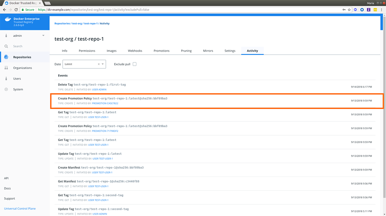
The following table breaks down the data included in an event and uses
the highlighted Create Promotion Policy event as an example.
| Event detail | Description | Example |
|---|---|---|
| Label | Friendly name of the event. | Create Promotion Policy |
| Repository | This will always be the repository in review following the
<user-or-org>/<repository_name> convention outlined in
Create a repository |
test-org/test-repo-1 |
| Tag | Tag affected by the event, when applicable. | test-org/test-repo-1:latest where latest is the affected tag |
| SHA | The digest value for ``CREATE` operations such as creating a new image tag or a promotion policy. | sha256:bbf09ba3 |
| Type | Event type. Possible values are: CREATE, GET, UPDATE,
DELETE, SEND, FAIL and SCAN. |
CREATE |
| Initiated by | The actor responsible for the event. For user-initiated events, this
will reflect the user ID and link to that user’s profile. For image
events triggered by a policy – pruning, pull / push mirroring, or
promotion – this will reflect the relevant policy ID except for manual
promotions where it reflects PROMOTION MANUAL_P, and link to the
relevant policy page. Other event actors may not include a link. |
PROMOTION CA5E7822 |
| Date and Time | When the event happened in your configured time zone. | 2018 9:59 PM |
Given the level of detail on each event, it should be easy for MSR and security admins to determine what events have taken place inside of MSR. For example, when an image which shouldn’t have been deleted ends up getting deleted, the security admin can determine when and who initiated the deletion.
For more details on different permission levels within MSR, see Authentication and authorization in MSR to understand the minimum level required to view the different repository events.
| Repository event | Description | Minimum permission level |
|---|---|---|
| Push | Refers to Create Manifest and Update Tag events. Learn more
about pushing images. |
Authenticated users |
| Scan | Requires security scanning to be set
up by a MSR admin.
Once enabled, this will display as a SCAN event type. |
Authenticated users |
| Promotion | Refers to a Create Promotion Policy event which links to the
Promotions tab of the repository where you can edit
the existing promotions. See Promotion Policies for different ways to promote
an image. |
Repository admin |
| Delete | Refers to “Delete Tag” events. Learn more about Delete images. | Authenticated users |
| Pull | Refers to “Get Tag” events. Learn more about Pull an image. | Repository admin |
| Mirror | Refers to Pull mirroring and Push mirroring events.
See Mirror images to another registry and
Mirror images from another registry for more details. |
Repository admin |
| Create repo | Refers to Create Repository events. See
Create a repository for more details. |
Authenticated users |
Where to go next
Enable Auto-Deletion of Repository Events
Mirantis Secure Registry has a global setting for repository event auto-deletion. This allows event records to be removed as part of garbage collection. MSR administrators can enable auto-deletion of repository events based on specified conditions which are covered below.
In your browser, navigate to :samp:https://<msr-url> and log in with your admin credentials.
Select System from the left navigation pane which displays the Settings page by default.
Scroll down to Repository Events and turn on Auto-Deletion.
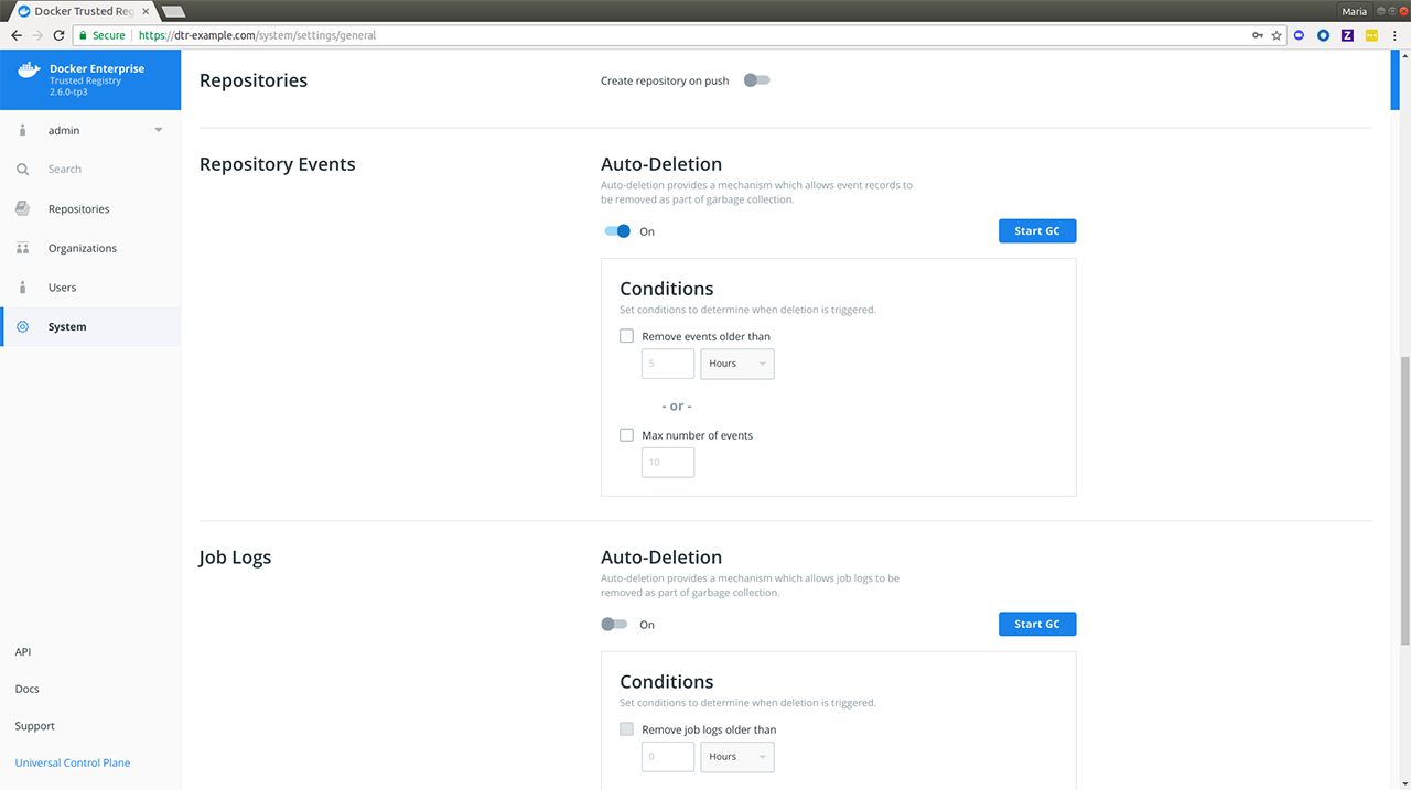
Specify the conditions with which an event auto-deletion will be triggered.
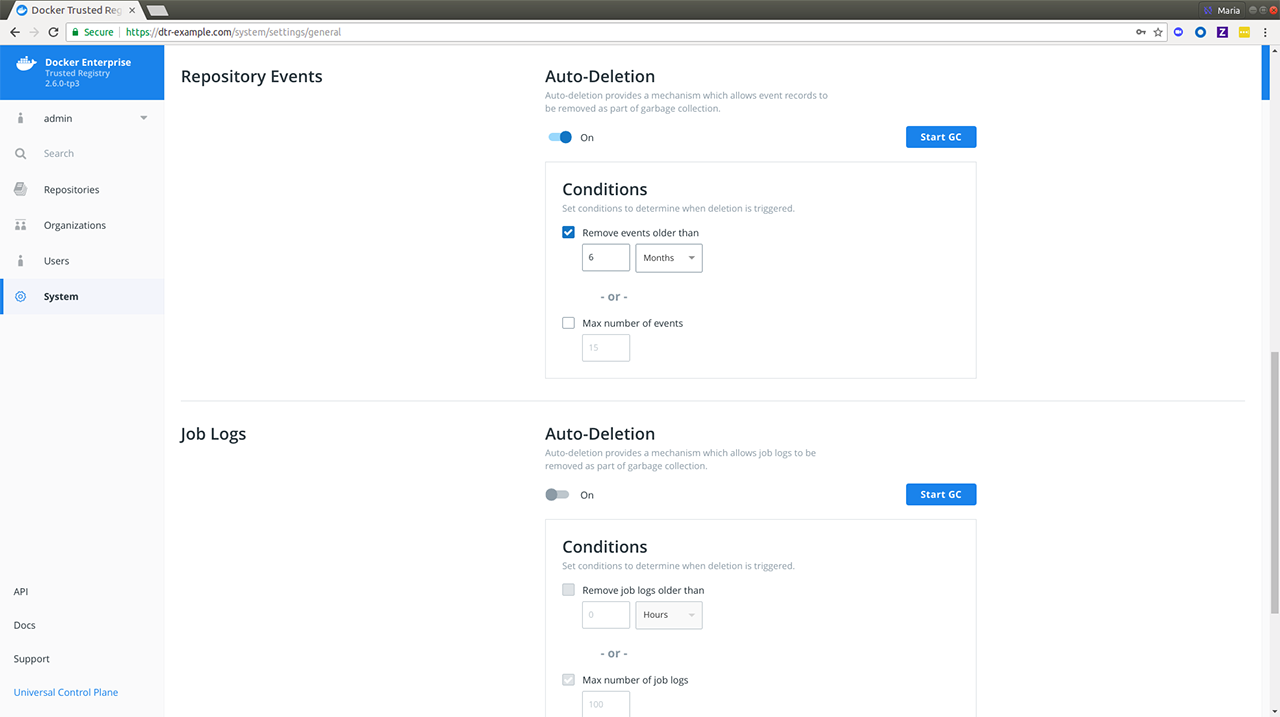
MSR allows you to set your auto-deletion conditions based on the following optional repository event attributes:
| Name | Description | Example |
|---|---|---|
| Age | Lets you remove events older than your specified number of hours, days, weeks or months. | 2 months |
| Max number of events | Lets you specify the maximum number of events allowed in the repositories. | 6000 |
If you check and specify both, events in your repositories will be removed during garbage collection if either condition is met. You should see a confirmation message right away.
Click Start GC if you’re ready. Read more about garbage collection if you’re unsure about this operation.
Navigate to System > Job Logs to confirm that
onlinegchas happened.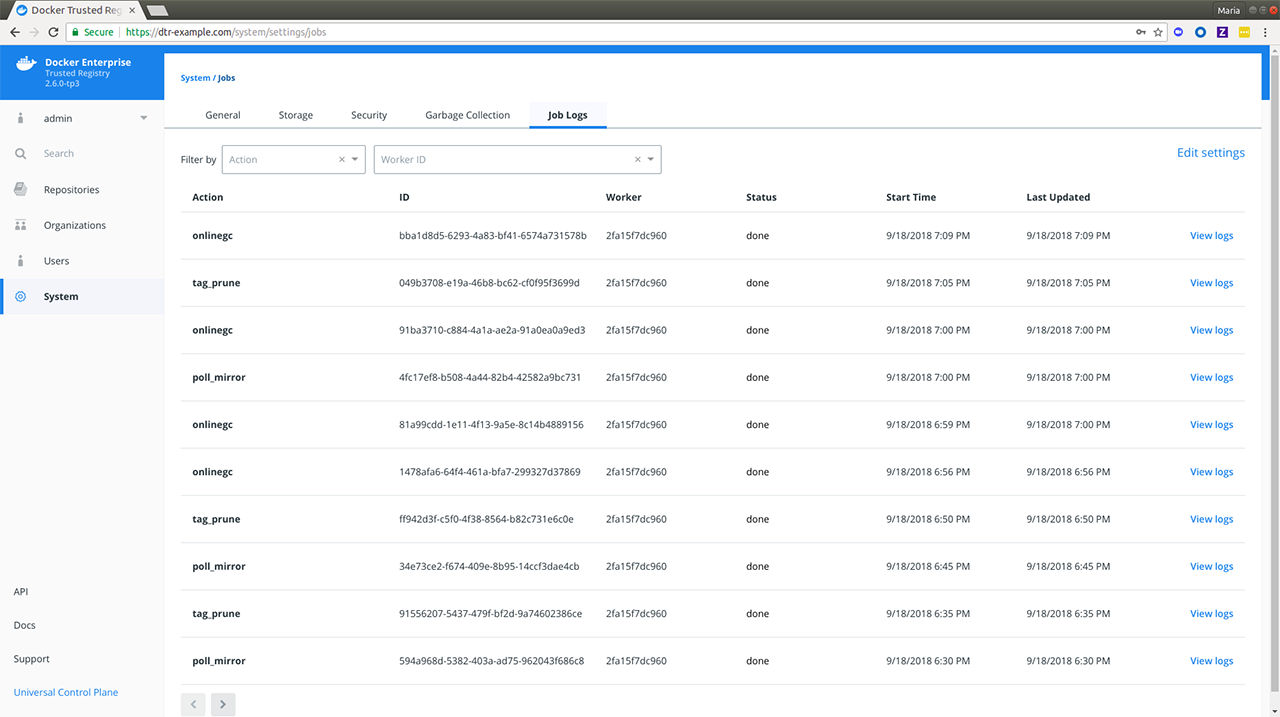
Where to go next
Manage applications
With the introduction of the experimental app plugin to the Docker CLI, MSR has been enhanced to include application management. In MSR 2.7, you can push an app to your MSR repository and have an application be clearly distinguished from individual and multi-architecture container images, as well as plugins. When you push an application to MSR, you see two image tags:
| Image | Tag | Type | Under the hood |
|---|---|---|---|
| Invocation | <app_tag>-invoc |
Container image represented by OS and architecture (e.g.
linux amd64) |
Uses Mirantis Container Runtime. The Docker daemon is responsible for building and pushing the image. |
| Application with bundled components | <app_tag> |
Application | Uses the app client to build and push the image. docker app is
experimental on the Docker client. |
Notice the app-specific tags, app and app-invoc, with scan
results for the bundled components in the former and the invocation
image in the latter. To view the scanning results for the bundled
components, click “View Details” next to the app tag.
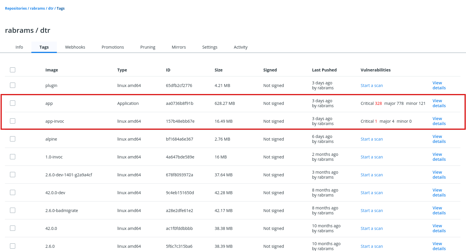
Click on the image name or digest to see the vulnerabilities for that specific image.
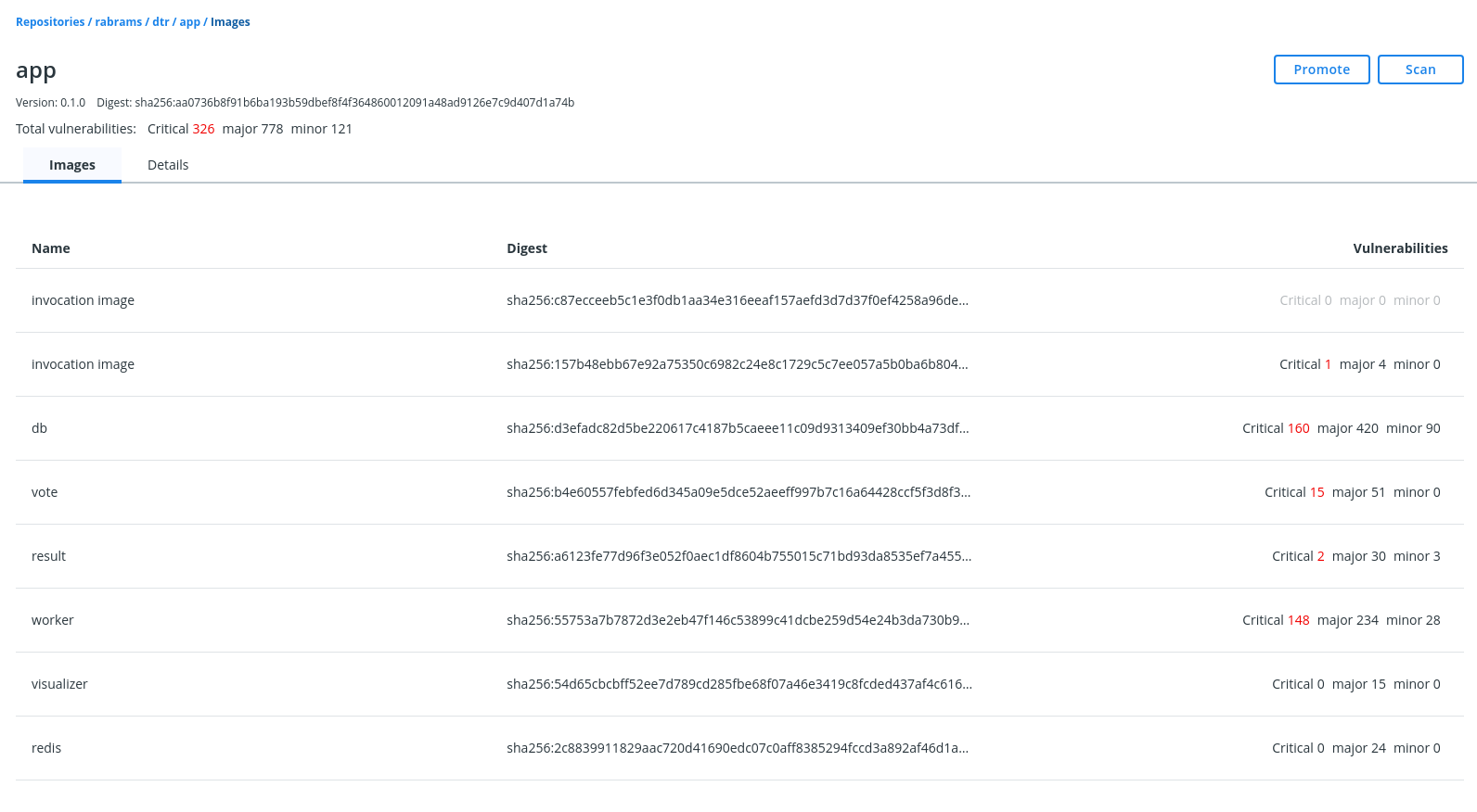
Parity with existing repository and image features
The following repository and image management events also apply to applications:
- Creation
- MSR pushes
- Vulnerability scans
- Vulnerability overrides
- Deletion
- Immutable tags
- Promotion policies
Limitations
- You cannot sign an application since the Notary signer cannot sign OCI (Open Container Initiative) indices.
- Scanning-based policies do not take effect until after all images bundled in the application have been scanned.
- Docker Content Trust (DCT) does not work for applications and multi-arch images, which are the same under the hood.
Troubleshooting tips
x509 certificate errors
fixing up "35.165.223.150/admin/lab-words:0.1.0" for push: failed to resolve "35.165.223.150/admin/lab-words:0.1.0-invoc", push the image to the registry before pushing the bundle: failed to do request: Head https://35.165.223.150/v2/admin/lab-words/manifests/0.1.0-invoc: x509: certificate signed by unknown authority
Check that your MSR has been configured with your TLS certificate’s
Fully Qualified Domain Name (FQDN). See Configure
MSR for more details.
For docker app testing purposes, you can pass the
--insecure-registries option for pushing an application`.
docker app push hello-world --tag 35.165.223.150/admin/lab-words:0.1.0 --insecure-registries 35.165.223.150
35.165.223.150/admin/lab-words:0.1.0-invoc
Successfully pushed bundle to 35.165.223.150/admin/lab-words:0.1.0. Digest is sha256:bd1a813b6301939fa46e617f96711e0cca1e4065d2d724eb86abde6ef7b18e23.
Known Issues
See MSR 2.7 Release Notes - Known Issues for known issues related to applications in MSR.
Manage access tokens
Mirantis Secure Registry lets you create and distribute access tokens to enable programmatic access to MSR. Access tokens are linked to a particular user account and duplicate whatever permissions that account has at the time of use. If the account changes permissions, so will the token.
Access tokens are useful in cases such as building integrations since you can issue multiple tokens – one for each integration – and revoke them at any time.
Create an access token
To create an access token for the first time, log in to
https://<msr-url>with your MKE credentials.Expand your Profile from the left navigation pane and select Profile > Access Tokens.
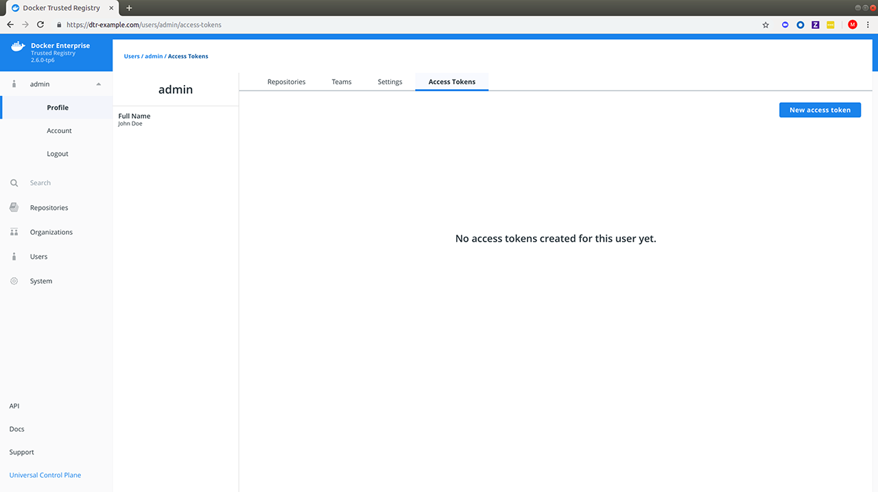
Add a description for your token. Use something that indicates where the token is going to be used, or set a purpose for the token. Administrators can also create tokens for other users.
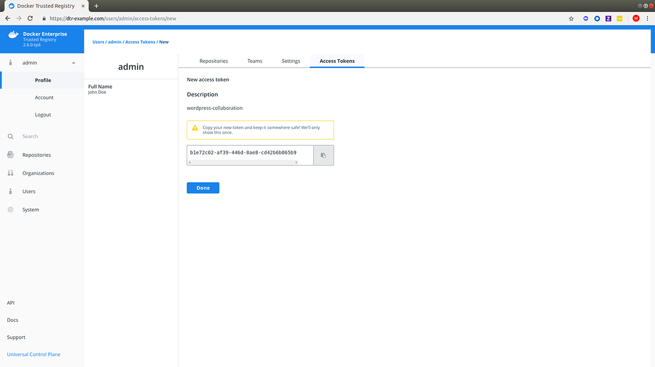
Modify an access token
Once the token is created, you will not be able to see it again. You do have the option to rename, deactivate, or delete the token as needed. You can delete the token by selecting it and clicking Delete, or you can click View Details:
Use the access token
You can use an access token anywhere that requires your MSR password. As
an example you can pass your access token to the --password or
-p option when logging in from your Docker CLI client:
docker login dtr.example.org --username <username> --password <token>
To use the MSR API to list the repositories your user has access to:
curl --silent --insecure --user <username>:<token> dtr.example.org/api/v0/repositories
Tag pruning
Tag pruning is the process of cleaning up unnecessary or unwanted repository tags. As of v2.6, you can configure the Mirantis Secure Registry (MSR) to automatically perform tag pruning on repositories that you manage by:
- Specifying a tag pruning policy or alternatively,
- Setting a tag limit
Tag Pruning
When run, tag pruning only deletes a tag and does not carry out any actual blob deletion. For actual blob deletions, see Garbage Collection.
Known Issue
While the tag limit field is disabled when you turn on immutability for a new repository, this is currently not the case with Repository Settings. As a workaround, turn off immutability when setting a tag limit via Repository Settings > Pruning.
In the following section, we will cover how to specify a tag pruning policy and set a tag limit on repositories that you manage. It will not include modifying or deleting a tag pruning policy.
Specify a tag pruning policy
As a repository administrator, you can now add tag pruning policies on
each repository that you manage. To get started, navigate to
https://<msr-url> and log in with your credentials.
Select Repositories on the left navigation pane, and then click on
the name of the repository that you want to update. Note that you will
have to click on the repository name following the / after the
specific namespace for your repository.
Select the Pruning tab, and click New pruning policy to specify your tag pruning criteria:
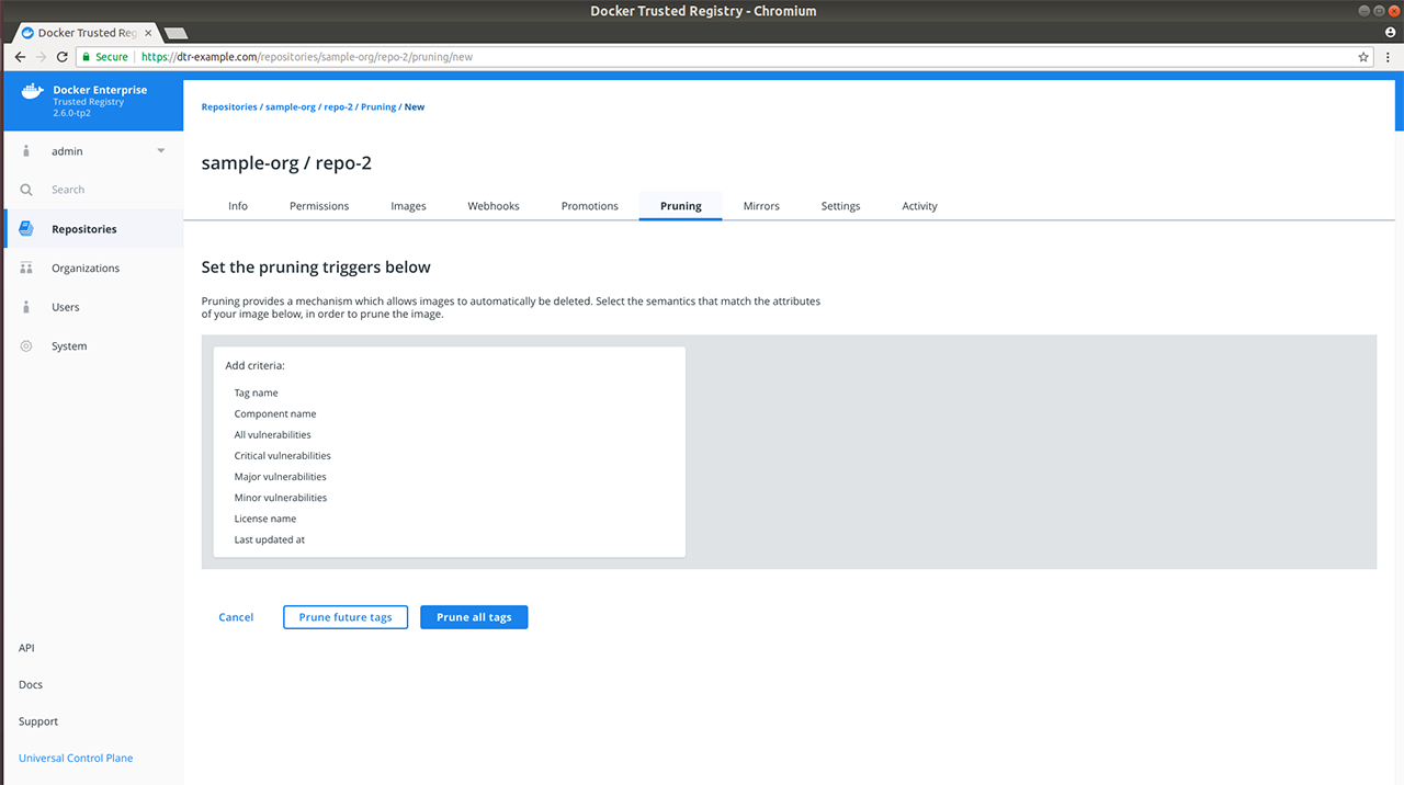
MSR allows you to set your pruning triggers based on the following image attributes:
| Name | Description | Example |
|---|---|---|
| Tag name | Whether the tag name equals, starts with, ends with, contains, is one of, or is not one of your specified string values | Tag name = test` |
| Component name | Whether the image has a given component and the component name equals, starts with, ends with, contains, is one of, or is not one of your specified string values | Component name starts with b |
| Vulnerabilities | Whether the image has vulnerabilities – critical, major, minor, or all – and your selected vulnerability filter is greater than or equals, greater than, equals, not equals, less than or equals, or less than your specified number | Critical vulnerabilities = 3 |
| License | Whether the image uses an intellectual property license and is one of or not one of your specified words | License name = docker |
| Last updated at | Whether the last image update was before your specified number of hours, days, weeks, or months. For details on valid time units, see Go’s ParseDuration function | Last updated at: Hours = 12 |
Specify one or more image attributes to add to your pruning criteria, then choose:
- Prune future tags to save the policy and apply your selection to future tags. Only matching tags after the policy addition will be pruned during garbage collection.
- Prune all tags to save the policy, and evaluate both existing and future tags on your repository.
Upon selection, you will see a confirmation message and will be redirected to your newly updated Pruning tab.
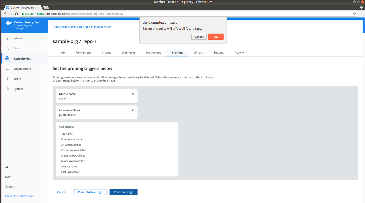
If you have specified multiple pruning policies on the repository, the Pruning tab will display a list of your prune triggers and details on when the last tag pruning was performed based on the trigger, a toggle for deactivating or reactivating the trigger, and a View link for modifying or deleting your selected trigger.
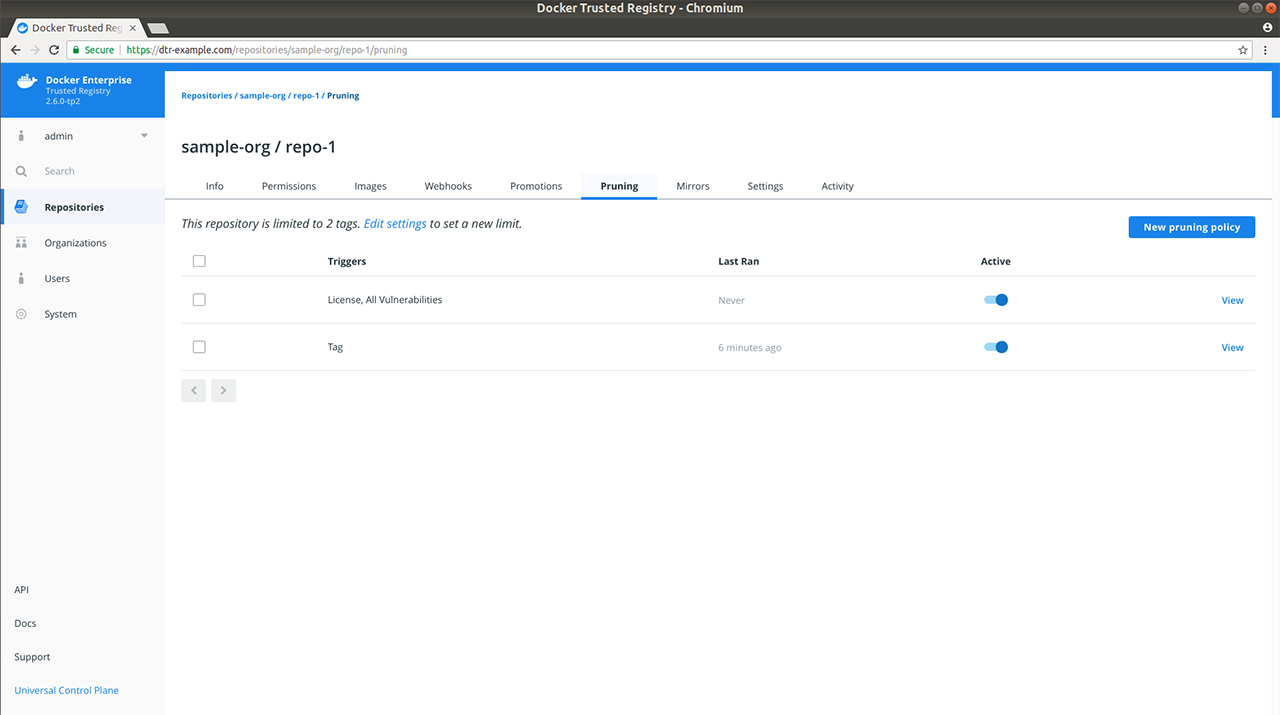
All tag pruning policies on your account are evaluated every 15 minutes. Any qualifying tags are then deleted from the metadata store. If a tag pruning policy is modified or created, then the tag pruning policy for the affected repository will be evaluated.
Set a tag limit
In addition to pruning policies, you can also set tag limits on repositories that you manage to restrict the number of tags on a given repository. Repository tag limits are processed in a first in first out (FIFO) manner. For example, if you set a tag limit of 2, adding a third tag would push out the first.
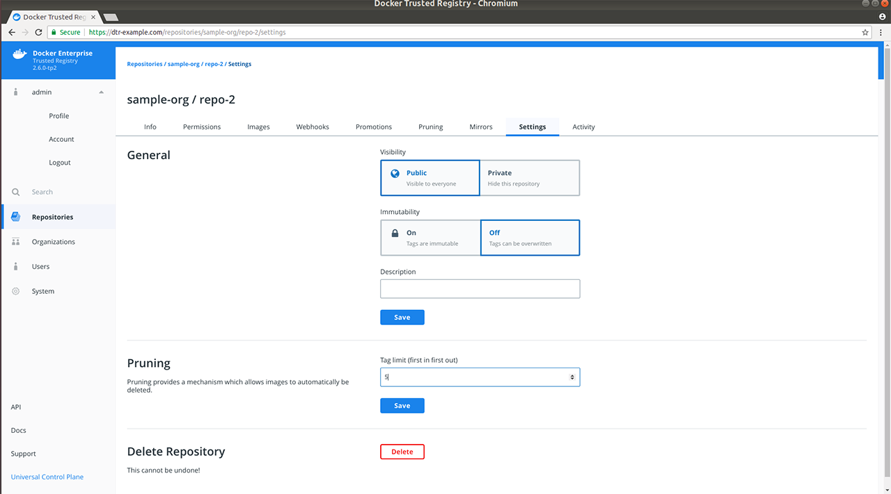
To set a tag limit, do the following:
Select the repository that you want to update and click the Settings tab.
Turn off immutability for the repository.
Specify a number in the Pruning section and click Save. The Pruning tab will now display your tag limit above the prune triggers list along with a link to modify this setting.
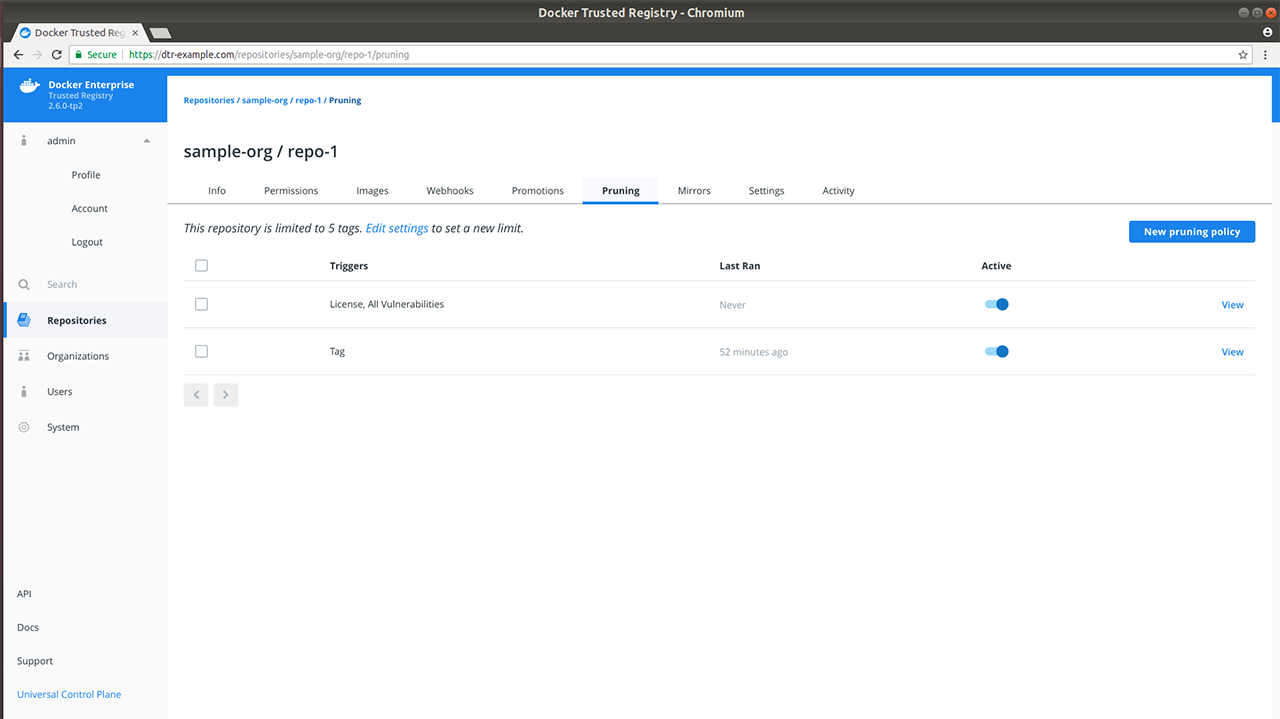
Where to go next
Deprecation notice
This document outlines the functionalities or components within MSR that will be deprecated.
Enable Manifest List via the API
2.5 and 2.6
Since v2.5, it has been possible for repository admins to
autogenerate manifest lists when creating a repository via the
API. You accomplish this by
setting enableManifestLists to true when sending a POST request
to the /api/v0/repositories/{namespace} endpoint. When enabled for a
repository, any image that you push to an existing tag will be appended
to the list of manifests for that tag. enableManifestLists is set to
false by default, which means pushing a new image to an existing tag
will overwrite the manifest entry for that tag.
2.7
The above behavior and the enableManifestLists field will be removed
in v2.7. Starting in v2.7, you can use the MSR CLI to create and
push a manifest list to any repository.
MSR API
MSR CLI reference
The CLI tool has commands to install, configure, and backup Mirantis Secure Registry (MSR). It also allows uninstalling DTR. By default the tool runs in interactive mode. It prompts you for the values needed.
Additional help is available for each command with the ‘–help’ option.
Usage
docker run -it --rm mirantis/dtr \
command [command options]
If not specified, docker/dtr uses the latest tag by default. To
work with a different version, specify it in the command. For example,
docker run -it --rm docker/dtr:2.6.0.
Commands
mirantis/msr backup
Create a backup of MSR
Usage
docker run -i --rm mirantis/dtr \
backup [command options] > backup.tar
docker run -i --rm --log-driver none docker/dtr:2.7.5 \
backup --ucp-ca "$(cat ca.pem)" --existing-replica-id 5eb9459a7832 > backup.tar
The following command has been tested on Linux:
DTR_VERSION=$(docker container inspect $(docker container ps -f \
name=dtr-registry -q) | grep -m1 -Po '(?<=DTR_VERSION=)\d.\d.\d'); \
REPLICA_ID=$(docker inspect -f '{{.Name}}' $(docker ps -q -f name=dtr-rethink) | cut -f 3 -d '-'); \
read -p 'ucp-url (The MKE URL including domain and port): ' UCP_URL; \
read -p 'ucp-username (The MKE administrator username): ' UCP_ADMIN; \
read -sp 'ucp password: ' UCP_PASSWORD; \
docker run --log-driver none -i --rm \
--env UCP_PASSWORD=$UCP_PASSWORD \
docker/dtr:$DTR_VERSION backup \
--ucp-username $UCP_ADMIN \
--ucp-url $UCP_URL \
--ucp-ca "$(curl https://${UCP_URL}/ca)" \
--existing-replica-id $REPLICA_ID > \
dtr-metadata-${DTR_VERSION}-backup-$(date +%Y%m%d-%H_%M_%S).tar
Description
This command creates a tar file with the contents of the volumes
used by MSR, and prints it. You can then use mirantis/dtr restore to
restore the data from an existing backup.
Note
This command only creates backups of configurations, and image metadata. It does not back up users and organizations. Users and organizations can be backed up during a MKE backup.
It also does not back up Docker images stored in your registry. You should implement a separate backup policy for the Docker images stored in your registry, taking into consideration whether your MSR installation is configured to store images on the filesystem or is using a cloud provider.
This backup contains sensitive information and should be stored securely.
Using the
--offline-backupflag temporarily shuts down the RethinkDB container. Take the replica out of your load balancer to avoid downtime.
Options
| Option | Environment variable | Description |
|---|---|---|
--debug |
$DEBUG | Enable debug mode for additional logs. |
--existing-replica-i |
$DTR_REPLICA_ID | The ID of an existing MSR replica. To add, remove or modify a MSR replica, you must connect to an existing healthy replica’s database. |
--help-extended |
$$DTR_EXTENDED_HELP | Display extended help text for a given command. |
--offline-backup |
$DTR_OFFLINE_BACKUP | This flag takes RethinkDB down during backup and takes a more reliable backup. If you back up MSR with this flag, RethinkDB will go down during backup. However, offline backups are guaranteed to be more consistent than online backups. |
--ucp-ca |
$UCP_CA | Use a PEM-encoded TLS CA certificate for MKE. Download the MKE
TLS CA certificate from https://<mke-url>/ca, and use --ucp-ca
"$(cat ca.pem)". |
--ucp-insecure-tls |
$UCP_INSECURE_TLS | Disable TLS verification for MKE. The installation
uses TLS but always trusts the TLS certificate used by MKE, which can
lead to MITM (man-in-the-middle) attacks. For production deployments,
use --ucp-ca "$(cat ca.pem)" instead. |
--ucp-password |
$UCP_PASSWORD | The MKE administrator password. |
--ucp-url |
$UCP_URL | The MKE URL including domain and port. |
--ucp-username |
$UCP_USERNAME | The MKE administrator username. |
mirantis/dtr destroy
Destroy a MSR replica’s data
Usage
docker run -it --rm mirantis/dtr \
destroy [command options]
Description
This command forcefully removes all containers and volumes associated with a MSR replica without notifying the rest of the cluster. Use this command on all replicas uninstall MSR.
Use the ‘remove’ command to gracefully scale down your MSR cluster.
Options
| Option | Environment variable | Description |
|---|---|---|
--replica-id |
$DTR_DESTROY_REPLICA_ID | The ID of the replica to destroy. |
--ucp-url |
$UCP_URL | The MKE URL including domain and port. |
--ucp-username |
$UCP_USERNAME | The MKE administrator username. |
--ucp-password |
$UCP_PASSWORD | The MKE administrator password. |
--debug |
$DEBUG | Enable debug mode for additional logs. |
--help-extended |
$DTR_EXTENDED_HELP | Display extended help text for a given command. |
--ucp-insecure-tls |
$UCP_INSECURE_TLS | Disable TLS verification for MKE. The installation uses TLS but always
trusts the TLS certificate used by MKE, which can lead to man-in-the-middle attacks. For production deployments, use
--ucp-ca “$(cat ca.pem)” instead. |
--ucp-ca |
$UCP_CA | Use a PEM-encoded TLS CA certificate for MKE.Download the MKE TLS CA
certificate from https:// /ca, and use --ucp-ca "$(cat ca.pem)". |
mirantis/dtr emergency-repair
Recover MSR from loss of quorum
Usage
docker run -it --rm mirantis/dtr \
emergency-repair [command options]
Description
This command repairs a MSR cluster that has lost quorum by reverting your cluster to a single MSR replica.
There are three steps you can take to recover an unhealthy MSR cluster:
- If the majority of replicas are healthy, remove the unhealthy nodes from the cluster, and join new ones for high availability.
- If the majority of replicas are unhealthy, use this command to revert your cluster to a single MSR replica.
- If you can’t repair your cluster to a single replica, you’ll have to
restore from an existing backup, using the
restorecommand.
When you run this command, a MSR replica of your choice is repaired and
turned into the only replica in the whole MSR cluster. The containers
for all the other MSR replicas are stopped and removed. When using the
force option, the volumes for these replicas are also deleted.
After repairing the cluster, you should use the join command to add
more MSR replicas for high availability.
Options
| Option | Environment variable | Description |
|---|---|---|
--debug |
$DEBUG | Enable debug mode for additional logs. |
--existing-replica-id |
$DTR_REPLICA_ID | The ID of an existing MSR replica. To add, remove or modify MSR, you must connect to an existing healthy replica’s database. |
--help-extended |
$DTR_EXTENDED_HELP | Display extended help text for a given command. |
--overlay-subnet |
$DTR_OVERLAY_SUBNET | The subnet used by the dtr-ol overlay network.
Example: 10.0.0.0/24. For high-availability, MSR creates an overlay
network between MKE nodes. This flag allows you to choose the subnet for
that network. Make sure the subnet you choose is not used on any machine
where MSR replicas are deployed. |
--prune |
$PRUNE | Delete the data volumes of all unhealthy replicas. With this option, the volume of the MSR replica you’re restoring is preserved but the volumes for all other replicas are deleted. This has the same result as completely uninstalling MSR from those replicas. |
--ucp-ca |
$UCP_CA | Use a PEM-encoded TLS CA certificate for MKE. Download the MKE
TLS CA certificate from https:// /ca, and use --ucp-ca "$(cat
ca.pem)". |
--ucp-insecure-tls |
$UCP_INSECURE_TLS | Disable TLS verification for MKE. The installation
uses TLS but always trusts the TLS certificate used by MKE, which can
lead to MITM (man-in-the-middle) attacks. For production deployments,
use --ucp-ca "$(cat ca.pem)" instead. |
--ucp-password |
$UCP_PASSWORD | The MKE administrator password. |
--ucp-url |
$UCP_URL | The MKE URL including domain and port. |
--ucp-username |
$UCP_USERNAME | The MKE administrator username. |
--y, yes |
$YES | Answer yes to any prompts. |
mirantis/dtr images
List all the images necessary to install MSR
Usage
docker run -it --rm mirantis/dtr \
images [command options]
Description
This command lists all the images necessary to install MSR.
mirantis/dtr install
Install Mirantis Secure Registry
Usage
docker run -it --rm mirantis/dtr \
install [command options]
Description
This command installs Mirantis Secure Registry (MSR) on a node managed by Mirantis Kubernetes Engine (MKE).
After installing MSR, you can join additional MSR replicas using
mirantis/dtr join.
Example Usage
$ docker run -it --rm docker/dtr:2.7.5 install \
--ucp-node <MKE_NODE_HOSTNAME> \
--ucp-insecure-tls
Note
Use --ucp-ca "$(cat ca.pem)" instead of --ucp-insecure-tls for a production deployment.
Options
| Option | Environment variable | Description |
|---|---|---|
--async-nfs |
$ASYNC_NFS | Use async NFS volume options on the replica specified in the
--existing-replica-id option. The NFS configuration must be set with
--nfs-storage-url explicitly to use this option. Using
--async-nfs will bring down any containers on the replica that use
the NFS volume, delete the NFS volume, bring it back up with the
appropriate configuration, and restart any containers that were brought
down. |
--client-cert-auth-ca |
$CLIENT_CA | Specify root CA certificates for client authentication with
--client-cert-auth-ca "$(cat ca.pem)". |
--debug |
$DEBUG | Enable debug mode for additional logs. |
--dtr-ca |
$DTR_CA | Use a PEM-encoded TLS CA certificate for MSR. By default MSR generates a
self-signed TLS certificate during deployment. You can use your own root
CA public certificate with --dtr-ca "$(cat ca.pem)". |
--dtr-cert |
$DTR_CERT | Use a PEM-encoded TLS certificate for MSR. By default MSR generates a
self-signed TLS certificate during deployment. You can use your own
public key certificate with --dtr-cert "$(cat cert.pem)". If the
certificate has been signed by an intermediate certificate authority,
append its public key certificate at the end of the file to establish a
chain of trust. |
--dtr-external-url |
$DTR_EXTERNAL_URL | URL of the host or load balancer clients use to reach MSR. When you use
this flag, users are redirected to MKE for logging in. Once
authenticated they are redirected to the URL you specify in this flag.
If you don’t use this flag, MSR is deployed without single sign-on with
MKE. Users and teams are shared but users log in separately into the two
applications. You can enable and disable single sign-on within your MSR
system settings. Format https://host[:port], where port is the
value you used with --replica-https-port. Since HSTS (HTTP
Strict-Transport-Security) header is included in all API responses, make
sure to specify the FQDN (Fully Qualified Domain Name) of your MSR, or
your browser may refuse to load the web interface. |
--dtr-key |
$DTR_KEY | Use a PEM-encoded TLS private key for MSR. By default MSR generates a
self-signed TLS certificate during deployment. You can use your own TLS
private key with --dtr-key "$(cat key.pem)". |
--dtr-storage-volume |
$DTR_STORAGE_VOLUME | Customize the volume to store Docker images. By default MSR creates a
volume to store the Docker images in the local filesystem of the node
where MSR is running, without high-availability. Use this flag to
specify a full path or volume name for MSR to store images. For
high-availability, make sure all MSR replicas can read and write data on
this volume. If you’re using NFS, use --nfs-storage-url instead. |
--enable-client-cert-auth |
$ENABLE_CLIENT_CERT_AUTH | Enables TLS client certificate authentication; use
--enable-client-cert-auth=false to disable it. If enabled, MSR will
additionally authenticate users via TLS client certificates. You must
also specify the root certificate authorities (CAs) that issued the
certificates with --client-cert-auth-ca. |
--enable-pprof |
$DTR_PPROF | Enables pprof profiling of the server. Use --enable-pprof=false to
disable it. Once MSR is deployed with this flag, you can access the pprof
endpoint for the api server at /debug/pprof, and the registry
endpoint at /registry_debug_pprof/debug/pprof. |
--help-extended |
$DTR_EXTENDED_HELP | Display extended help text for a given command. |
--http-proxy |
$DTR_HTTP_PROXY | The HTTP proxy used for outgoing requests. |
--https-proxy |
$DTR_HTTPS_PROXY | The HTTPS proxy used for outgoing requests. |
--log-host |
$LOG_HOST | The syslog system to send logs to. The endpoint to send logs to. Use
this flag if you set --log-protocol to tcp or udp. |
--log-level |
$LOG_LEVEL | Log level for all container logs when logging to syslog. Default: INFO. The supported log levels are debug, info, warn, error, or fatal. |
--log-protocol |
$LOG_PROTOCOL | The protocol for sending logs. Default is internal. By default, MSR
internal components log information using the logger specified in the
Docker daemon in the node where the MSR replica is deployed. Use this
option to send MSR logs to an external syslog system. The supported
values are tcp, udp, or internal. Internal is the default
option, stopping MSR from sending logs to an external system. Use this
flag with --log-host. |
--nfs-storage-url |
$NFS_STORAGE_URL | Use NFS to store Docker images following this format: nfs://<ip|
hostname>/<mountpoint>. By default, MSR creates a volume to store the
Docker images in the local filesystem of the node where MSR is running,
without high availability. To use this flag, you need to install an NFS
client library like nfs-common in the node where you’re deploying MSR.
You can test this by running showmount -e <nfs-server>. When you
join new replicas, they will start using NFS so there is no need to
specify this flag. To reconfigure MSR to stop using NFS, leave this
option empty: --nfs-storage-url "". See USE NFS for more details. |
--nfs-options |
$NFS_OPTIONS | Pass in NFS volume options verbatim for the replica specified in the
--existing-replica-id option. The NFS configuration must be set with
--nfs-storage-url explicitly to use this option. Specifying
--nfs-options will pass in character-for-character the options
specified in the argument when creating or recreating the NFS volume.
For instance, to use NFS v4 with async, pass in “rw,nfsvers=4,async” as
the argument. |
--no-proxy |
$DTR_NO_PROXY | List of domains the proxy should not be used for. When using
--http-proxy you can use this flag to specify a list of domains that
you don’t want to route through the proxy. Format acme.com[, acme.org]. |
--overlay-subnet |
$DTR_OVERLAY_SUBNET | The subnet used by the dtr-ol overlay network. Example: 10.0.0.0/24.
For high-availability, MSR creates an overlay network between MKE nodes.
This flag allows you to choose the subnet for that network. Make sure
the subnet you choose is not used on any machine where MSR replicas are
deployed. |
--replica-http-port |
$REPLICA_HTTP_PORT | The public HTTP port for the MSR replica. Default is 80. This allows
you to customize the HTTP port where users can reach MSR. Once users
access the HTTP port, they are redirected to use an HTTPS connection,
using the port specified with --replica-https-port. This port can
also be used for unencrypted health checks. |
--replica-https-port |
$REPLICA_HTTPS_PORT | The public HTTPS port for the MSR replica. Default is 443. This
allows you to customize the HTTPS port where users can reach MSR. Each
replica can use a different port. |
--replica-id |
$DTR_INSTALL_REPLICA_ID | Assign a 12-character hexadecimal ID to the MSR replica. Random by default. |
--replica-rethinkdb-cache-mb |
$RETHINKDB_CACHE_MB | The maximum amount of space in MB for RethinkDB in-memory cache used by
the given replica. Default is auto. Auto is (available_memory - 1024)
/ 2. This config allows changing the RethinkDB cache usage per replica.
You need to run it once per replica to change each one. |
--ucp-ca |
$UCP_CA | Use a PEM-encoded TLS CA certificate for MKE. Download the MKE TLS CA
certificate from https://<mke-url>/ca, and use --ucp-ca "$(cat ca.pem)". |
--ucp-insecure-tls |
$UCP_INSECURE_TLS | Disable TLS verification for MKE. The installation uses TLS but always
trusts the TLS certificate used by MKE, which can lead to MITM
(man-in-the-middle) attacks. For production deployments, use --ucp-ca
"$(cat ca.pem)" instead. |
--ucp-node |
$UCP_NODE | The hostname of the MKE node to deploy MSR. Random by default. You can
find the hostnames of the nodes in the cluster in the MKE web interface,
or by running docker node ls on a MKE manager node. |
--ucp-password |
$UCP_PASSWORD | The MKE administrator password. |
--ucp-url |
$UCP_URL | The MKE URL including domain and port. |
--ucp-username |
$UCP_USERNAME | The MKE administrator username. |
mirantis/dtr join
Add a new replica to an existing MSR cluster. Use SSH to log into any node that is already part of MKE.
Usage
docker run -it --rm \
docker/dtr:2.7.5 join \
--ucp-node <mke-node-name> \
--ucp-insecure-tls
Description
This command creates a replica of an existing MSR on a node managed by Mirantis Kubernetes Engine (MKE).
For setting MSR for high-availability, create 3, 5, or 7 replicas of MSR.
Options
| Option | Environment variable | Description |
|---|---|---|
--debug |
$DEBUG | Enable debug mode for additional logs. |
--existing-replica-id |
$DTR_REPLICA_ID | The ID of an existing MSR replica. To add, remove or modify MSR, you must connect to an existing healthy replica’s database. |
--help-extended |
$DTR_EXTENDED_HELP | Display extended help text for a given command. |
--replica-http-port |
$REPLICA_HTTP_PORT | The public HTTP port for the MSR replica. Default is 80. This allows
you to customize the HTTP port where users can reach MSR. Once users
access the HTTP port, they are redirected to use an HTTPS connection,
using the port specified with --replica-https-port. This port can
also be used for unencrypted health checks. |
--replica-https-port |
$REPLICA_HTTPS_PORT | The public HTTPS port for the MSR replica. Default is 443. This
allows you to customize the HTTPS port where users can reach MSR. Each
replica can use a different port. |
--replica-id |
$DTR_INSTALL_REPLICA_ID | Assign a 12-character hexadecimal ID to the MSR replica. Random by default. |
--replica-rethinkdb-cache-mb |
$RETHINKDB_CACHE_MB | The maximum amount of space in MB for RethinkDB in-memory cache used by
the given replica. Default is auto. Auto is (available_memory - 1024)
/ 2. This config allows changing the RethinkDB cache usage per
replica. You need to run it once per replica to change each one. |
--skip-network-test |
$DTR_SKIP_NETWORK_TEST | Don’t test if overlay networks are working correctly between MKE nodes. For high-availability, MSR creates an overlay network between MKE nodes and tests that it is working when joining replicas. Don’t use this option for production deployments. |
--ucp-ca |
$UCP_CA | Use a PEM-encoded TLS CA certificate for MKE.Download the MKE TLS CA
certificate from https://<mke-url>/ca, and use --ucp-ca "$(cat
ca.pem)". |
--ucp-insecure-tls |
$UCP_INSECURE_TLS | Disable TLS verification for MKE. The installation uses TLS but always
trusts the TLS certificate used by MKE, which can lead to MITM
(man-in-the-middle) attacks. For production deployments, use --ucp-ca
"$(cat ca.pem)" instead. |
--ucp-node |
$UCP_NODE | The hostname of the MKE node to deploy MSR. Random by default.You can find the hostnames of the nodes in the cluster in the MKE web interface, or by running docker node ls on a MKE manager node. |
--ucp-password |
$UCP_PASSWORD | The MKE administrator password. |
--ucp-url |
$UCP_URL | The MKE URL including domain and port. |
--ucp-username |
$UCP_USERNAME | The MKE administrator username. |
--unsafe-join |
$DTR_UNSAFE_JOIN | Join a new replica even if the cluster is unhealthy.Joining replicas to an unhealthy MSR cluster leads to split-brain scenarios, and data loss. Don’t use this option for production deployments. |
mirantis/dtr reconfigure
Change MSR configurations.
Usage
docker run -it --rm mirantis/dtr \
reconfigure [command options]
Description
This command changes MSR configuration settings. If you are using NFS as a storage volume, see Configuring MSR for NFS for details on changes to the reconfiguration process.
MSR is restarted for the new configurations to take effect. To have no down time, configure your MSR for high availability.
Options
| Option | Environment variable | Description |
|---|---|---|
--async-nfs |
$ASYNC_NFS | Use async NFS volume options on the replica specified in the
--existing-replica-id option. The NFS configuration must be set with
--nfs-storage-url explicitly to use this option. Using
--async-nfs will bring down any containers on the replica that use
the NFS volume, delete the NFS volume, bring it back up with the
appropriate configuration, and restart any containers that were brought
down. |
--client-cert-auth-ca |
$CLIENT_CA | Specify root CA certificates for client authentication with
--client-cert-auth-ca "$(cat ca.pem)". |
--debug |
$DEBUG | Enable debug mode for additional logs of this bootstrap container (the
log level of downstream MSR containers can be set with --log-level). |
--dtr-ca |
$DTR_CA | Use a PEM-encoded TLS CA certificate for MSR. By default MSR generates a
self-signed TLS certificate during deployment. You can use your own root
CA public certificate with --dtr-ca "$(cat ca.pem)". |
--dtr-cert |
$DTR_CERT | Use a PEM-encoded TLS certificate for MSR. By default MSR generates a
self-signed TLS certificate during deployment. You can use your own
public key certificate with --dtr-cert "$(cat cert.pem)". If the
certificate has been signed by an intermediate certificate authority,
append its public key certificate at the end of the file to establish a
chain of trust. |
--dtr-external-url |
$DTR_EXTERNAL_URL | URL of the host or load balancer clients use to reach MSR. When you use
this flag, users are redirected to MKE for logging in. Once
authenticated they are redirected to the url you specify in this flag.
If you don’t use this flag, MSR is deployed without single sign-on with
MKE. Users and teams are shared but users login separately into the two
applications. You can enable and disable single sign-on in the MSR
settings. Format https://host[:port], where port is the value you
used with --replica-https-port. Since HSTS (HTTP
Strict-Transport-Security) header is included in all API responses, make
sure to specify the FQDN (Fully Qualified Domain Name) of your MSR, or
your browser may refuse to load the web interface. |
--dtr-key |
$DTR_KEY | Use a PEM-encoded TLS private key for MSR. By default MSR generates a
self-signed TLS certificate during deployment. You can use your own TLS
private key with --dtr-key "$(cat key.pem)". |
--dtr-storage-volume |
$DTR_STORAGE_VOLUME | Customize the volume to store Docker images. By default MSR creates a
volume to store the Docker images in the local filesystem of the node
where MSR is running, without high-availability. Use this flag to
specify a full path or volume name for MSR to store images. For
high-availability, make sure all MSR replicas can read and write data on
this volume. If you’re using NFS, use --nfs-storage-url instead. |
--enable-client-cert-auth |
$ENABLE_CLIENT_CERT_AUTH | Enables TLS client certificate authentication; use
--enable-client-cert-auth=false to disable it. If enabled, MSR will
additionally authenticate users via TLS client certificates. You must
also specify the root certificate authorities (CAs) that issued the
certificates with --client-cert-auth-ca. |
--enable-pprof |
$DTR_PPROF | Enables pprof profiling of the server. Use --enable-pprof=false to
disable it. Once MSR is deployed with this flag, you can access the
pprof endpoint for the api server at /debug/pprof, and the registry
endpoint at /registry_debug_pprof/debug/pprof. |
--existing-replica-id |
$DTR_REPLICA_ID | The ID of an existing MSR replica. To add, remove or modify MSR, you must connect to an existing healthy replica’s database. |
--help-extended |
$DTR_EXTENDED_HELP | Display extended help text for a given command. |
--http-proxy |
$DTR_HTTP_PROXY | The HTTP proxy used for outgoing requests. |
--https-proxy |
$DTR_HTTPS_PROXY | The HTTPS proxy used for outgoing requests. |
--log-host |
$LOG_HOST | The syslog system to send logs to. The endpoint to send logs to. Use
this flag if you set --log-protocol to tcp or udp. |
--log-level |
$LOG_LEVEL | Log level for all container logs when logging to syslog. Default: INFO.
The supported log levels are debug, info, warn, error, or fatal. |
--log-protocol |
$LOG_PROTOCOL | The protocol for sending logs. Default is internal. By default, MSR
internal components log information using the logger specified in the
Docker daemon in the node where the MSR replica is deployed. Use this
option to send MSR logs to an external syslog system. The supported
values are tcp, udp, and internal. Internal is the default
option, stopping MSR from sending logs to an external system. Use this flag with --log-host. |
--nfs-storage-url |
$NFS_STORAGE_URL | When running DTR 2.5 (with experimental online garbage
collection) and MSR 2.6.0-2.6.3, there is an issue with reconfiguring
and restoring DTR with --nfs-storage-url which leads to erased tags.
Make sure to back up your DTR metadata before you proceed. To work
around the issue, manually create a storage volume on each DTR node and
reconfigure DTR with --dtr-storage-volume and your newly-created
volume instead. See Reconfigure Using a Local NFS Volume for more
details. To reconfigure DTR to stop using NFS, leave this option empty:
–nfs-storage-url “”. See USE NFS for more details. Upgrade to MSR 2.6.4
and follow Best practice for data migration in MSR 2.6.4 when switching
storage backends. |
--nfs-options |
$NFS_OPTIONS | Pass in NFS volume options verbatim for the replica specified in the
--existing-replica-id option. The NFS configuration must be set with
--nfs-storage-url explicitly to use this option. Specifying
--nfs-options will pass in character-for-character the options
specified in the argument when creating or recreating the NFS volume.
For instance, to use NFS v4 with async, pass in “rw,nfsvers=4,async” as
the argument. |
--no-proxy |
$DTR_NO_PROXY | List of domains the proxy should not be used for. When using
--http-proxy you can use this flag to specify a list of domains that
you don’t want to route through the proxy. Format acme.com[, acme.org]. |
--replica-http-port |
$REPLICA_HTTP_PORT | The public HTTP port for the MSR replica. Default is 80. This allows
you to customize the HTTP port where users can reach MSR. Once users
access the HTTP port, they are redirected to use an HTTPS connection,
using the port specified with –replica-https-port. This port can also
be used for unencrypted health checks. |
--replica-https-port |
$REPLICA_HTTPS_PORT | The public HTTPS port for the MSR replica. Default is 443. This
allows you to customize the HTTPS port where users can reach MSR. Each
replica can use a different port. |
--replica-rethinkdb-cache-mb |
$RETHINKDB_CACHE_MB | The maximum amount of space in MB for RethinkDB in-memory cache used by
the given replica. Default is auto. Auto is (available_memory - 1024)
/ 2. This config allows changing the RethinkDB cache usage per
replica. You need to run it once per replica to change each one. |
--storage-migrated |
$STORAGE_MIGRATED | A flag added in MSR 2.6.4 which lets you indicate the migration status of your storage data. Specify this flag if you are migrating to a new storage backend and have already moved all contents from your old backend to your new one. If not specified, MSR will assume the new backend is empty during a backend storage switch, and consequently destroy your existing tags and related image metadata. |
--ucp-ca |
$UCP_CA | Use a PEM-encoded TLS CA certificate for MKE. Download the MKE TLS CA
certificate from https://<mke-url>/ca, and use --ucp-ca "$(cat ca.pem)". |
--ucp-password |
$UCP_PASSWORD | The MKE administrator password. |
--ucp-url |
$UCP_URL | The MKE URL including domain and port. |
--ucp-username |
$UCP_USERNAME | The MKE administrator username. |
mirantis/dtr remove
Remove a MSR replica from a cluster
Usage
docker run -it --rm mirantis/dtr \
remove [command options]
Description
This command gracefully scales down your MSR cluster by removing exactly one replica. All other replicas must be healthy and will remain healthy after this operation.
Options
| Option | Environment variable | Description |
|---|---|---|
--debug |
$DEBUG | Enable debug mode for additional logs. |
--existing-replica-id |
$DTR_REPLICA_ID | The ID of an existing MSR replica. To add, remove or modify MSR, you must connect to an existing healthy replica’s database. |
--help-extended |
$DTR_EXTENDED_HELP | Display extended help text for a given command. |
--replica-id |
$DTR_REMOVE_REPLICA_ID | DEPRECATED Alias for --replica-ids |
--replica-ids |
$DTR_REMOVE_REPLICA_IDS | A comma separated list of IDs of replicas to remove from the cluster. |
--ucp-ca |
$UCP_CA | Use a PEM-encoded TLS CA certificate for MKE. Download the MKE TLS CA
certificate from https://<mke-url>/ca, and use --ucp-ca "$(cat ca.pem)". |
--ucp-insecure-tls |
$UCP_INSECURE_TLS | Disable TLS verification for MKE. The installation uses TLS but always
trusts the TLS certificate used by MKE, which can lead to MITM
(man-in-the-middle) attacks. For production deployments, use --ucp-ca
"$(cat ca.pem)" instead. |
--ucp-password |
$UCP_PASSWORD | The MKE administrator password. |
--ucp-url |
$UCP_URL | The MKE URL including domain and port. |
--ucp-username |
$UCP_USERNAME | The MKE administrator username. |
mirantis/dtr restore
Install and restore MSR from an existing backup
Usage
docker run -i --rm mirantis/dtr \
restore [command options] < backup.tar
Description
This command performs a fresh installation of MSR, and reconfigures it
with configuration data from a tar file generated by
`mirantis/dtr backup <backup.md>`__. If you are restoring MSR after a
failure, please make sure you have destroyed the old MSR fully.
There are three steps you can take to recover an unhealthy MSR cluster:
- If the majority of replicas are healthy, remove the unhealthy nodes from the cluster, and join new nodes for high availability.
- If the majority of replicas are unhealthy, use this command to revert your cluster to a single MSR replica.
- If you can’t repair your cluster to a single replica, you’ll have to
restore from an existing backup, using the
restorecommand.
This command does not restore Docker images. You should implement a separate restore procedure for the Docker images stored in your registry, taking in consideration whether your MSR installation is configured to store images on the local filesystem or using a cloud provider.
After restoring the cluster, you should use the join command to add
more MSR replicas for high availability.
Options
| Option | Environment variable | Description |
|---|---|---|
--debug |
$DEBUG | Enable debug mode for additional logs. |
--dtr-ca |
$DTR_CA | Use a PEM-encoded TLS CA certificate for MSR. By default MSR generates a
self-signed TLS certificate during deployment. You can use your own TLS
CA certificate with --dtr-ca "$(cat ca.pem)". |
--dtr-cert |
$DTR_CERT | Use a PEM-encoded TLS certificate for MSR. By default MSR generates a
self-signed TLS certificate during deployment. You can use your own TLS
certificate with --dtr-cert "$(cat ca.pem)". |
--dtr-external-url |
$DTR_EXTERNAL_URL | URL of the host or load balancer clients use to reach MSR. When you use
this flag, users are redirected to MKE for logging in. Once
authenticated they are redirected to the URL you specify in this flag.
If you don’t use this flag, MSR is deployed without single sign-on with
MKE. Users and teams are shared but users log in separately into the two
applications. You can enable and disable single sign-on within your MSR
system settings. Format https://host[:port], where port is the value
you used with --replica-https-port. |
--dtr-key |
$DTR_KEY | Use a PEM-encoded TLS private key for MSR. By default MSR generates a
self-signed TLS certificate during deployment. You can use your own TLS
private key with --dtr-key "$(cat ca.pem)". |
--dtr-storage-volume |
$DTR_STORAGE_VOLUME | Mandatory flag to allow for MSR to fall back to your configured storage setting at the time of backup. If you have previously configured MSR to use a full path or volume name for storage, specify this flag to use the same setting on restore. See mirantis/dtr install and mirantis/dtr reconfigure for usage details. |
--dtr-use-default-storage |
$DTR_DEFAULT_STORAGE | Mandatory flag to allow for MSR to fall back to your configured storage backend at the time of backup. If cloud storage was configured, then the default storage on restore is cloud storage. Otherwise, local storage is used. With DTR 2.5 (with experimental online garbage collection) and MSR 2.6.0-2.6.3, this flag must be specified in order to keep your MSR metadata. If you encounter an issue with lost tags, see Restore to Cloud Storage for Docker’s recommended recovery strategy. Upgrade to MSR 2.6.4 and follow Best practice for data migration in MSR 2.6.4 when switching storage backends. |
--nfs-storage-url |
$NFS_STORAGE_URL | Mandatory flag to allow for MSR to fall back to your configured storage
setting at the time of backup. When running DTR 2.5 (with experimental
online garbage collection) and MSR 2.6.0-2.6.3, there is an issue with
reconfiguring and restoring DTR with --nfs-storage-url which leads
to erased tags. Make sure to back up your DTR metadata before you
proceed. If NFS was previously configured, you have to manually create a
storage volume on each DTR node and specify --dtr-storage-volume
with the newly-created volume instead. See Restore to a Local NFS Volume
for more details. For additional NFS configuration options to support
NFS v4, see mirantis/dtr install and mirantis/dtr reconfigure.
Upgrade to MSR 2.6.4 and follow Best practice for data migration in MSR
2.6.4 when switching storage backends. |
--enable-pprof |
$DTR_PPROF | Enables pprof profiling of the server. Use --enable-pprof=false to
disable it. Once MSR is deployed with this flag, you can access the
pprof endpoint for the api server at /debug/pprof, and the registry
endpoint at /registry_debug_pprof/debug/pprof. |
--help-extended |
$DTR_EXTENDED_HELP | Display extended help text for a given command. |
--http-proxy |
$DTR_HTTP_PROXY | The HTTP proxy used for outgoing requests. |
--https-proxy |
$DTR_HTTPS_PROXY | The HTTPS proxy used for outgoing requests. |
--log-host |
$LOG_HOST | The syslog system to send logs to.The endpoint to send logs to. Use this
flag if you set --log-protocol to tcp or udp. |
--log-level |
$LOG_LEVEL | Log level for all container logs when logging to syslog. Default:
INFO. The supported log levels are debug, info, warn,
error, or fatal. |
--log-protocol |
$LOG_PROTOCOL | The protocol for sending logs. Default is internal.By default, MSR
internal components log information using the logger specified in the
Docker daemon in the node where the MSR replica is deployed. Use this
option to send MSR logs to an external syslog system. The supported
values are tcp, udp, and internal. Internal is the default option,
stopping MSR from sending logs to an external system. Use this flag with --log-host. |
--no-proxy |
$DTR_NO_PROXY | List of domains the proxy should not be used for.When using
--http-proxy you can use this flag to specify a list of domains that
you don’t want to route through the proxy. Format acme.com[, acme.org]. |
--replica-http-port |
$REPLICA_HTTP_PORT | The public HTTP port for the MSR replica. Default is 80. This allows
you to customize the HTTP port where users can reach MSR. Once users
access the HTTP port, they are redirected to use an HTTPS connection,
using the port specified with --replica-https-port. This port can
also be used for unencrypted health checks. |
--replica-https-port |
$REPLICA_HTTPS_PORT | The public HTTPS port for the MSR replica. Default is 443. This
allows you to customize the HTTPS port where users can reach MSR. Each
replica can use a different port. |
--replica-id |
$DTR_INSTALL_REPLICA_ID | Assign a 12-character hexadecimal ID to the MSR replica. Random by default. |
--replica-rethinkdb-cache-mb |
$RETHINKDB_CACHE_MB | The maximum amount of space in MB for RethinkDB in-memory cache used by
the given replica. Default is auto. Auto is (available_memory - 1024)
/ 2. This config allows changing the RethinkDB cache usage per
replica. You need to run it once per replica to change each one. |
--ucp-ca |
$UCP_CA | Use a PEM-encoded TLS CA certificate for MKE. Download the MKE TLS CA
certificate from https://<mke-url>/ca, and use --ucp-ca "$(cat
ca.pem)". |
--ucp-insecure-tls |
$UCP_INSECURE_TLS | Disable TLS verification for MKE. The installation uses TLS but always
trusts the TLS certificate used by MKE, which can lead to MITM
(man-in-the-middle) attacks. For production deployments, use --ucp-ca
"$(cat ca.pem)" instead. |
--ucp-node |
$UCP_NODE | The hostname of the MKE node to deploy MSR. Random by default. You can
find the hostnames of the nodes in the cluster in the MKE web interface,
or by running docker node ls on a MKE manager node. |
--ucp-password |
$UCP_PASSWORD | The MKE administrator password. |
--ucp-url |
$UCP_URL | The MKE URL including domain and port. |
--ucp-username |
$UCP_USERNAME | The MKE administrator username. |
mirantis/dtr upgrade
Upgrade DTR 2.5.x cluster to this version
Usage
docker run -it --rm mirantis/dtr \
upgrade [command options]
Description
This command upgrades DTR 2.5.x to the current version of this image.
Options
| Option | Environment variable | Description |
|---|---|---|
--debug |
$DEBUG | Enable debug mode for additional logs. |
--existing-replica-id |
$DTR_REPLICA_ID | The ID of an existing MSR replica. To add, remove or modify MSR, you must connect to an existing healthy replica’s database. |
--help-extended |
$DTR_EXTENDED_HELP | Display extended help text for a given command. |
--ucp-ca |
$UCP_CA | Use a PEM-encoded TLS CA certificate for MKE. Download the MKE TLS CA
certificate from https://<mke-url>/ca, and use --ucp-ca "$(cat ca.pem)". |
--ucp-insecure-tls |
$UCP_INSECURE_TLS | Disable TLS verification for MKE. The installation uses TLS but always
trusts the TLS certificate used by MKE, which can lead to MITM
(man-in-the-middle) attacks. For production deployments, use --ucp-ca
"$(cat ca.pem)" instead. |
--ucp-password |
$UCP_PASSWORD | The MKE administrator password. |
--ucp-url |
$UCP_URL | The MKE URL including domain and port. |
--ucp-username |
$UCP_USERNAME | The MKE administrator username. |
Docker Engine - Enterprise is now MCR
The product formerly known as Docker Engine - Enterprise is now Mirantis Container Runtime (MCR).
Warning
Mirantis stopped maintaining this documentation set as of 2021-07-21, in correlation with the End of Life date for MKE 3.2.x and MSR 2.7.x. The company continues to support MCR 19.03.x and its documentation.
For the latest MKE, MSR, and MCR product documentation, refer to:
Mirantis Container Runtime
Mirantis Container Runtime is a client-server application with these major components:
- A server which is a type of long-running program called a daemon process (the dockerd command).
- A REST API which specifies interfaces that programs can use to talk to the daemon and instruct it what to do.
- A command line interface (CLI) client (the docker command).
Mirantis Container Runtime can be installed on several linux distros as well as on Windows.
Mirantis Container Runtime release notes
This document describes the latest changes, additions, known issues, and fixes for Mirantis Container Runtime.
Mirantis Container Runtime builds upon the corresponding Docker Engine - Community that it references. Mirantis Container Runtime includes enterprise features as well as back-ported fixes (security-related and priority defects) from the open source. It also incorporates defect fixes for environments in which new features cannot be adopted as quickly for consistency and compatibility reasons.
Note
The client and container runtime are in separate packages from
the daemon. Users should install and update
all three packages at the same time to get the latest patch releases.
For example, on Ubuntu:
sudo apt-get install docker-ee docker-ee-cli containerd.io. See
the install instructions for the corresponding linux distro for
details.
Version 19.03
19.03.17
(2021-06-29)
Components
| Component | Version |
|---|---|
| Mirantis Container Runtime | 19.03.17 |
| containerd | 1.4.6 |
| runc | 1.0.0-rc95 |
Networking
- Fixed an issue wherein overlapping IP addresses could occur due to nodes failing to clean up their old load balancer IP addresses (FIELD-3915).
Packaging
- Updated containerd to version 1.4.6 and runc to version 1.0.0-rc95 to address CVE-2021-30465 (ENGINE-482).
19.03.16
(2021-05-17)
Components
| Component | Version |
|---|---|
| Mirantis Container Runtime | 19.03.16 |
| containerd | 1.3.10 |
| runc | 1.0.0-rc10 |
Packaging
- Added a technical preview for cri-docker (previously known as dockershim).
- Fixed an issue wherein killing containerd caused systemd to stop docker.
Networking
Fixed an issue wherein swarm service VIPs timed out from Windows containers, resulting in the following error in dockerd event logs:
Failed to add ILB policy for service service […] failed during hnsCallRawResponse: hnsCall failed in Win32: The specified port already exists.
The Windows Operating System update KB4577668 introduced the issue on October 13, 2020, affecting all versions of MCR (FIELD-3310).
Known issues
Centos and RHEL 7.x kernels can experience memory exhaustion due to slab cache usage. Because this is a kernel feature, the issue cannot be resolved with MCR code.
Workarounds:
- (Recommended) Update to a kernel that supports setting
cgroups.memory=nokmemand apply the change (for customers using Centos or RHEL 7.7 and above). - Increase the memory available to the machine for slab usage.
(FIELD-3466)
- (Recommended) Update to a kernel that supports setting
19.03.15
(2021-04-12)
Components
| Component | Version |
|---|---|
| Mirantis Container Runtime | 19.03.15 |
| containerd | 1.3.10 |
| runc | 1.0.0-rc10 |
Security
- Resolved CVE-2021-21285, thereby preventing invalid images from crashing the Docker daemon (ENGINE-437).
- Resolved CVE-2021-21284, thereby preventing a remapped root from accessing the Docker state by locking down file permissions (ENGINE-437).
- MCR now confirms that AppArmor and SELinux profiles are applied when building with BuildKit (ENGINE-437).
- Resolved CVE-2021-21334, and in the process updated containerd to version 1.3.10 (ENGINE-437).
Client
- MCR now evaluates contexts before import to reduce the risk of extracted files escaping the context store (ENGINE-437).
19.03.14
(2021-03-01)
No changes were made to MCR for the March 1, 2021 software patch (only MKE is affected). As such, the product retains the 19.03.14 version number and there are no new release notes to report.
(2021-02-02)
No changes were made to MCR for the February 2, 2021 software patch (only MKE is affected). As such, the product retains the 19.03.14 version number and there are no new release notes to report.
(2020-12-17)
Components
| Component | Version |
|---|---|
| Docker Engine - Enterprise | 19.03.14 |
| containerd | 1.3.9 |
| runc | 1.0.0-rc10 |
Engine
- Fixed a memory leak related to the use of gcplogs (ENGINE-317).
- Bumped libnetwork to address null dereference in error handling (ENGINE-317).
Runtime
- Resolved an issue wherein containerd 1.7 binaries for RHEL 7.7 and 7.8 were missing (ENGINE-295).
Security
- Resolved CVE-2020-15257 (ENGINE-322).
19.03.13
(2020-11-12)
Components
| Component | Version |
|---|---|
| Mirantis Container Runtime | 19.03.13 |
| containerd | 1.3.7 |
| runc | 1.0.0-rc10 |
Client
- Bumped to golang version to 1.13.15 to address CVE-2020-16845.
- Fixed errors on close in config file write on Windows.
- Fixed an issue wherein Docker does not gracefully logout for non-default registry.
Engine
- Bumped to golang version to 1.13.15 to address CVE-2020-16845
- Fixes an issue where stopping a container did not remove it’s network namespace after running docker network disconnect cmd.
- Bumped aws-sdk-go to support IMDSv2.
19.03.12
(2020-08-10)
Client
- Fixed a command-line input regression on Windows
- Bumped to go1.13.13 to address CVE-2020-14039
- Bumped golang.org/x/text to address CVE-2020-14040
- Fix bug preventing logout from registry when using multiple config files (e.g. Windows vs WSL2 when using Docker Desktop)
- Fix regression preventing context metadata to be read
Engine
- Bumped to go1.13.13 to address CVE-2020-14039
- Fixed license warning regression on Windows
- Fixes to Microsoft/hcsshim to address issues in directory timestamps, log-rotation, and Windows container startup times.
- Bump vendor x/text to address CVE-2019-19794
19.03.11
(2020-06-24)
Networking
- Fix for ‘failed to get network during CreateEndpoint’
- Disable IPv6 Router Advertisements to prevent address spoofing. CVE-2020-13401
- Fix DNS fallback regression. moby/moby#41009
- Fix potential panic upon restart. moby/moby#40809
- Assign the correct network value to the default bridge Subnet field. moby/moby#40565
Client
- Fix version negotiation with older engine. docker/cli#2538
- Avoid setting SSH flags through hostname. docker/cli#2560
- Fix panic when DOCKER_CLI_EXPERIMENTAL is invalid. docker/cli#2558
- Upgrade Golang to 1.13.12
- Fix panic on single-character volumes. docker/cli#2471
- Lazy daemon feature detection to avoid long timeouts on simple commands. docker/cli#2442
- docker context inspect on Windows is now faster. docker/cli#2516
Runtime
- Upgrade Golang to 1.13.12
- overlay2: show backing filesystem. moby/moby#40652
- Update CRIU to v3.13 “Silicon Willet”. moby/moby#40850
- Use FILE_SHARE_DELETE for log files on Windows. moby/moby#40563
Rootless
- Supports numeric ID in /etc/subuid and /etc/subgid. moby/moby#40951
Builder
- buildkit: Fix concurrent map write panic when building multiple images in parallel. moby/moby#40780
- buildkit: Fix issue preventing chowning of non-root-owned files between stages with userns. moby/moby#40955
- Avoid creation of irrelevant temporary files on Windows. moby/moby#40877
Logging
- Avoid situation preventing container logs to rotate due to closing a closed log file. moby/moby#40921
Security
- apparmor: add missing rules for userns. moby/moby#40564
Swarm
- Fix issue where single swarm manager is stuck in Down state after reboot. moby/moby#40831
- tasks.db no longer grows indefinitely.
19.03.8
(2020-05-28)
Builder
- builder-next: Fix deadlock issues in corner cases.
- builder-next: Allow modern sign hashes for ssh forwarding.
- builder-next: Clear onbuild rules after triggering.
- builder-next: Fix issue with directory permissions when usernamespaces is enabled.
- Bump hcsshim to fix docker build failing on Windows 1903.
Networking
- Shorten controller ID in exec-root to not hit UNIX_PATH_MAX.
- Fix panic in drivers/overlay/encryption.go.
- Fix hwaddr set race between us and udev.
Runtime
- Fix docker crash when creating namespaces with UID in /etc/subuid and /etc/ subgid
- Fix rate limiting for logger, increase refill rate
- seccomp: add 64-bit time_t syscalls
- libnetwork: cleanup VFP during overlay network removal
- Improve mitigation for CVE-2019-14271 for some nscd configuration.
- overlay: remove modprobe execs.
- selinux: display better error messages when setting file labels.
- Speed up initial stats collection.
- rootless: use certs.d from XDG_CONFIG_HOME.
- Bump Golang 1.12.17.
- Bump google.golang.org/grpc to v1.23.1.
- Update containerd binary to v1.2.13.
- Prevent showing stopped containers as running in an edge case.
- Prevent potential lock.
- Update to runc v1.0.0-rc10.
- Fix possible runtime panic in Lgetxattr.
- rootless: fix proxying UDP packets.
Client
- Bump Golang 1.12.17.
- Bump google.golang.org/grpc to v1.23.1.
19.03.5
2019-11-14
Builder
- builder-next: Added
entitlementsin builder config. docker/engine#412 - Fix builder-next: permission errors on using build secrets or ssh forwarding with userns-remap. docker/engine#420
- Fix builder-next: copying a symlink inside an already copied directory. docker/engine#420
Packaging
- Support RHEL 8 packages
Runtime
- Bump Golang to 1.12.12. docker/engine#418
- Update to RootlessKit to v0.7.0 to harden slirp4netns with mount namespace and seccomp. docker/engine#397
- Fix to propagate GetContainer error from event processor. docker/engine#407
- Fix push of OCI image. docker/engine#405
19.03.4
2019-10-17
Networking
- Rollback libnetwork changes to fix
DOCKER-USERiptables chain issue. docker/engine#404
Known Issues
- In some circumstances with large clusters, Docker information might,
as part of the Swarm section, include the error
code = ResourceExhausted desc = grpc: received message larger than max (5351376 vs. 4194304). This does not indicate any failure or misconfiguration by the user, and requires no response. - Orchestrator port conflict can occur when redeploying all services as
new. Due to many Swarm manager requests in a short amount of time,
some services are not able to receive traffic and are causing a
404error after being deployed.- Workaround: restart all tasks via
docker service update --force.
- Workaround: restart all tasks via
- CVE-2018-15664
symlink-exchange attack with directory traversal. Workaround until
proper fix is available in upcoming patch release:
docker pausecontainer before doing file operations. moby/moby#39252 docker cpregression due to CVE mitigation. An error is produced when the source ofdocker cpis set to/.- Install Mirantis Container Runtime fails to install on RHEL on Azure.
This affects any RHEL version that uses an Extended Update Support
(EUS) image. At the time of this writing, known versions affected are
RHEL 7.4, 7.5, and 7.6.
- Workaround options:
- Use an older image and don’t get updates. Examples of EUS images are here: https://docs.microsoft.com/en-us/azure/virtual-machines/linux/rhel-images#rhel-images-with-eus.
- Import your own RHEL images into Azure and do not rely on the Extended Update Support (EUS) RHEL images.
- Use a RHEL image that does not contain a minor version in the SKU. These are not attached to EUS repositories. Some examples of those are the first three images (SKUs: 7-RAW, 7-LVM, 7-RAW-CI) listed here : https://docs.microsoft.com/en-us/azure/virtual-machines/linux/rhel-images#list-of-rhel-images-available.
- Workaround options:
19.03.3
2019-10-08
Security
- Patched
runcin containerd. CVE-2017-18367
Builder
- Fix builder-next: resolve digest for third party registries. docker/engine#339
- Fix builder-next: user namespace builds when daemon started with socket activation. docker/engine#373
- Fix builder-next; session: release forwarded ssh socket connection per connection. docker/engine#373
- Fix build-next: llbsolver: error on multiple cache importers. docker/engine#373
Client
- Added support for Docker Template 0.1.6.
- Mitigate against YAML files that have excessive aliasing. docker/cli#2119
Runtime
- Bump Golang to 1.12.10. docker/engine#387
- Bump containerd to 1.2.10. docker/engine#385
- Distribution: modify warning logic when pulling v2 schema1 manifests. docker/engine#368
- Fix
POST /images/createreturning a 500 status code when providing an incorrect platform option. docker/engine#365 - Fix
POST /buildreturning a 500 status code when providing an incorrect platform option. docker/engine#365 - Fix panic on 32-bit ARMv7 caused by misaligned struct member. docker/engine#363
- Fix to return “invalid parameter” when linking to non-existing container. docker/engine#352
- Fix overlay2: busy error on mount when using kernel >= 5.2. docker/engine#332
- Fix
docker rmistuck in certain misconfigured systems, e.g. dead NFS share. docker/engine#335 - Fix handling of blocked I/O of exec’d processes. docker/engine#296
- Fix jsonfile logger: follow logs stuck when
max-sizeis set andmax-file=1. docker/engine#378
Known Issues
DOCKER-USERiptables chain is missing: docker/for-linux#810. Users cannot perform additional container network traffic filtering on top of this iptables chain. You are not affected by this issue if you are not customizing iptable chains on top ofDOCKER-USER.Workaround: Insert the iptables chain after the docker daemon starts. For example:
iptables -N DOCKER-USER iptables -I FORWARD -j DOCKER-USERiptables -A DOCKER-USER -j RETURN
- In some circumstances with large clusters, docker information might,
as part of the Swarm section, include the error
code = ResourceExhausted desc = grpc: received message larger than max (5351376 vs. 4194304). This does not indicate any failure or misconfiguration by the user, and requires no response. - Orchestrator port conflict can occur when redeploying all services as
new. Due to many swarm manager requests in a short amount of time,
some services are not able to receive traffic and are causing a
404error after being deployed.- Workaround: restart all tasks via
docker service update --force.
- Workaround: restart all tasks via
- CVE-2018-15664
symlink-exchange attack with directory traversal. Workaround until
proper fix is available in upcoming patch release:
docker pausecontainer before doing file operations. moby/moby#39252 docker cpregression due to CVE mitigation. An error is produced when the source ofdocker cpis set to/.- Install Mirantis Container Runtime fails to install on RHEL on Azure.
This affects any RHEL version that uses an Extended Update Support
(EUS) image. At the time of this writing, known versions affected are
RHEL 7.4, 7.5, and 7.6.
- Workaround options:
- Use an older image and don’t get updates. Examples of EUS images are here: https://docs.microsoft.com/en-us/azure/virtual-machines/linux/rhel-images#rhel-images-with-eus.
- Import your own RHEL images into Azure and do not rely on the Extended Update Support (EUS) RHEL images.
- Use a RHEL image that does not contain a minor version in the SKU. These are not attached to EUS repositories. Some examples of those are the first three images (SKUs: 7-RAW, 7-LVM, 7-RAW-CI) listed here : https://docs.microsoft.com/en-us/azure/virtual-machines/linux/rhel-images#list-of-rhel-images-available.
- Workaround options:
19.03.2
2019-09-03
Builder
- Fix
COPY --fromto non-existing directory on Windows. moby/moby#39695 - Fix builder-next: metadata commands not having created time in history. moby/moby#39456
- Fix builder-next: close progress on layer export error. moby/moby#39782
- Update buildkit to 588c73e1e4. moby/moby#39781
Client
- Fix Windows absolute path detection on non-Windows docker/cli#1990
- Fix to zsh completion script for
docker login --username. - Fix context: produce consistent output on
context create. docker/cli#1985 - Fix support for HTTP proxy env variable. docker/cli#2059
Logging
- Fix for reading journald logs. moby/moby#37819 moby/moby#38859
Networking
- Prevent panic on network attached to a container with disabled networking. moby/moby#39589
Runtime
- Bump Golang to 1.12.8.
- Fix a potential engine panic when using XFS disk quota for containers. moby/moby#39644
Swarm
- Fix an issue where nodes with several tasks could not be removed. docker/swarmkit#2867
Known issues
- In some circumstances with large clusters, docker information might,
as part of the Swarm section, include the error
code = ResourceExhausted desc = grpc: received message larger than max (5351376 vs. 4194304). This does not indicate any failure or misconfiguration by the user, and requires no response. - Orchestrator port conflict can occur when redeploying all services as
new. Due to many swarm manager requests in a short amount of time,
some services are not able to receive traffic and are causing a
404error after being deployed.- Workaround: restart all tasks via
docker service update --force.
- Workaround: restart all tasks via
- Traffic cannot egress the HOST because of missing Iptables rules in
the FORWARD chain The missing rules are :
/sbin/iptables --wait -C FORWARD -o docker_gwbridge -m conntrack --ctstate RELATED,ESTABLISHED -j ACCEPT /sbin/iptables --wait -C FORWARD -o docker0 -m conntrack --ctstate RELATED,ESTABLISHED -j ACCEPT- Workaround: Add these rules back using a script and cron definitions. The script must contain ‘-C’ commands to check for the presence of a rule and ‘-A’ commands to add rules back. Run the script on a cron in regular intervals, for example, every minutes.
- Affected versions: 17.06.2-ee-16, 18.09.1, 19.03.0
- CVE-2018-15664
symlink-exchange attack with directory traversal. Workaround until
proper fix is available in upcoming patch release:
docker pausecontainer before doing file operations. moby/moby#39252 docker cpregression due to CVE mitigation. An error is produced when the source ofdocker cpis set to/.- Install Mirantis Container Runtime fails to install on RHEL on Azure.
This affects any RHEL version that uses an Extended Update Support
(EUS) image. At the time of this writing, known versions affected are
RHEL 7.4, 7.5, and 7.6.
- Workaround options:
- Use an older image and don’t get updates. Examples of EUS images are here: https://docs.microsoft.com/en-us/azure/virtual-machines/linux/rhel-images#rhel-images-with-eus.
- Import your own RHEL images into Azure and do not rely on the Extended Update Support (EUS) RHEL images.
- Use a RHEL image that does not contain a minor version in the SKU. These are not attached to EUS repositories. Some examples of those are the first three images (SKUs: 7-RAW, 7-LVM, 7-RAW-CI) listed here : https://docs.microsoft.com/en-us/azure/virtual-machines/linux/rhel-images#list-of-rhel-images-available.
- Workaround options:
19.03.1
2019-07-25
Security
- Fixed loading of nsswitch based config inside chroot under Glibc. CVE-2019-14271
Known issues
- In some circumstances, in large clusters, docker information might,
as part of the Swarm section, include the error
code = ResourceExhausted desc = grpc: received message larger than max (5351376 vs. 4194304). This does not indicate any failure or misconfiguration by the user, and requires no response. - Orchestrator port conflict can occur when redeploying all services as
new. Due to many swarm manager requests in a short amount of time,
some services are not able to receive traffic and are causing a
404error after being deployed.- Workaround: restart all tasks via
docker service update --force.
- Workaround: restart all tasks via
- Traffic cannot egress the HOST because of missing Iptables rules in
the FORWARD chain The missing rules are :
/sbin/iptables --wait -C FORWARD -o docker_gwbridge -m conntrack --ctstate RELATED,ESTABLISHED -j ACCEPT /sbin/iptables --wait -C FORWARD -o docker0 -m conntrack --ctstate RELATED,ESTABLISHED -j ACCEPT- Workaround: Add these rules back using a script and cron definitions. The script must contain ‘-C’ commands to check for the presence of a rule and ‘-A’ commands to add rules back. Run the script on a cron in regular intervals, for example, every minutes.
- Affected versions: 17.06.2-ee-16, 18.09.1, 19.03.0
- CVE-2018-15664
symlink-exchange attack with directory traversal. Workaround until
proper fix is available in upcoming patch release:
docker pausecontainer before doing file operations. moby/moby#39252 docker cpregression due to CVE mitigation. An error is produced when the source ofdocker cpis set to/.- Install Mirantis Container Runtime fails to install on RHEL on Azure.
This affects any RHEL version that uses an Extended Update Support
(EUS) image. At the time of this writing, known versions affected are
RHEL 7.4, 7.5, and 7.6.
- Workaround options:
- Use an older image and don’t get updates. Examples of EUS images are here: https://docs.microsoft.com/en-us/azure/virtual-machines/linux/rhel-images#rhel-images-with-eus.
- Import your own RHEL images into Azure and do not rely on the Extended Update Support (EUS) RHEL images.
- Use a RHEL image that does not contain a minor version in the SKU. These are not attached to EUS repositories. Some examples of those are the first three images (SKUs: 7-RAW, 7-LVM, 7-RAW-CI) listed here : https://docs.microsoft.com/en-us/azure/virtual-machines/linux/rhel-images#list-of-rhel-images-available.
- Workaround options:
19.03.0
2019-07-22
Builder
- Fixed
COPY --fromto preserve ownership. moby/moby#38599 - builder-next:
- Added inline cache support
--cache-from. docker/engine#215 - Outputs configuration allowed. moby/moby#38898
- Fixed gcr workaround token cache. docker/engine#212
stopprogresscalled on download error. docker/engine#215- Buildkit now uses systemd’s
resolv.conf. docker/engine#260. - Setting buildkit outputs now allowed. docker/cli#1766
- Look for Dockerfile specific dockerignore file (for example, Dockerfile.dockerignore) for ignored paths. docker/engine#215
- Automatically detect if process execution is possible for x86, arm, and arm64 binaries. docker/engine#215
- Updated buildkit to 1f89ec1. docker/engine#260
- Use Dockerfile frontend version
docker/dockerfile:1.1by default. docker/engine#215 - No longer rely on an external image for COPY/ADD operations. docker/engine#215
- Added inline cache support
Client
- Added
--pids-limitflag todocker update. docker/cli#1765 - Added systctl support for services. docker/cli#1754
- Added support for
template_driverin compose files. docker/cli#1746 - Added
--devicesupport for Windows. docker/cli#1606 - Added support for Data Path Port configuration. docker/cli#1509
- Added fast context switch: commands. docker/cli#1501
- Support added for
--mount type=bind,bind-nonrecursive,...docker/cli#1430 - Added maximum replicas per node. docker/cli#1612
- Added option to pull images quietly. docker/cli#882
- Added a separate
--domainnameflag. docker/cli#1130 - Added support for secret drivers in
docker stack deploy. docker/cli#1783 - Added ability to use swarm
ConfigsasCredentialSpecson services. docker/cli#1781 - Added
--security-opt systempaths=unconfinedsupport. docker/cli#1808 - Added basic framework for writing and running CLI plugins. docker/cli#1564 docker/cli#1898
- Bumped Docker App to v0.8.0. docker/docker-ce-packaging#341
- Added support for Docker buildx. docker/docker-ce-packaging#336
- Added support for Docker Assemble v0.36.0.
- Added support for Docker Cluster v1.0.0-rc2.
- Added support for Docker Template v0.1.4.
- Added support for Docker Registry v0.1.0-rc1.
- Bumped google.golang.org/grpc to v1.20.1. docker/cli#1884
- CLI changed to pass driver specific options to
docker run. docker/cli#1767 - Bumped Golang 1.12.5. docker/cli#1875
docker system infooutput now segregates information relevant to the client and daemon. docker/cli#1638- (Experimental) When targeting Kubernetes, added support for
x-pull-secret: some-pull-secretin compose-files service configs. docker/cli#1617 - (Experimental) When targeting Kubernetes, added support for
x-pull-policy: <Never|Always|IfNotPresent>in compose-files service configs. docker/cli#1617 - cp, save, export: Now preventing overwriting irregular files. docker/cli#1515
- npipe volume type on stack file now allowed. docker/cli#1195
- Fixed tty initial size error. docker/cli#1529
- Fixed problem with labels copying value from environment variables. docker/cli#1671
API
- Updated API version to v1.40. moby/moby#38089
- Added warnings to
/infoendpoint, and moved detection to the daemon. moby/moby#37502 - Added HEAD support for
/_pingendpoint. moby/moby#38570 - Added
Cache-Controlheaders to disable caching/_pingendpoint. moby/moby#38569 - Added
containerd,runc, anddocker-initversions to/version. moby/moby#37974 - Added undocumented
/grpcendpoint and registered BuildKit’s controller. moby/moby#38990
Experimental
- Enabled checkpoint/restore of containers with TTY. moby/moby#38405
- LCOW: Added support for memory and CPU limits. moby/moby#37296
- Windows: Added ContainerD runtime. moby/moby#38541
- Windows: LCOW now requires Windows RS5+. moby/moby#39108
Security
- mount: added BindOptions.NonRecursive (API v1.40). moby/moby#38003
- seccomp: whitelisted
io_pgetevents(). moby/moby#38895 - seccomp:
ptrace(2)for 4.8+ kernels now allowed. moby/moby#38137
Runtime
- Running
dockerdas a non-root user (Rootless mode) is now allowed. moby/moby#380050 - Rootless: optional support provided for
lxc-user-nicSUID binary. docker/engine#208 - Added DeviceRequests to HostConfig to support NVIDIA GPUs. moby/moby#38828
- Added
--devicesupport for Windows. moby/moby#37638 - Added
memory.kernelTCPsupport for linux. moby/moby#37043 - Windows credential specs can now be passed directly to the engine. moby/moby#38777
- Added pids-limit support in docker update. moby/moby#32519
- Added support for exact list of capabilities. moby/moby#38380
- daemon: Now use ‘private’ ipc mode by default. moby/moby#35621
- daemon: switched to semaphore-gated WaitGroup for startup tasks. moby/moby#38301
- Now use
idtools.LookupGroupinstead of parsing/etc/groupfile for docker.sock ownership to fix:api.go doesn't respect nsswitch.conf. moby/moby#38126 - cli: fixed images filter when using multi reference filter. moby/moby#38171
- Bumped Golang to 1.12.5. docker/engine#209
- Bumped
containerdto 1.2.6. moby/moby#39016 - Bumped
runcto 1.0.0-rc8, opencontainers/selinux v1.2.2. docker/engine#210 - Bumped
google.golang.org/grpcto v1.20.1. docker/engine#215 - Performance optimized in aufs and layer store for massively parallel container creation/removal. moby/moby#39135 moby/moby#39209
- Root is now passed to chroot for chroot Tar/Untar (CVE-2018-15664) moby/moby#39292
- Fixed
docker --initwith /dev bind mount. moby/moby#37665 - The right device number is now fetched when greater than 255 and
using the
--device-read-bpsoption. moby/moby#39212 - Fixed
Path does not existerror when path definitely exists. moby/moby#39251
Networking
- Moved IPVLAN driver out of experimental. moby/moby#38983
- Added support for ‘dangling’ filter. moby/moby#31551 docker/libnetwork#2230
- Load balancer sandbox is now deleted when a service is updated with
--network-rm. docker/engine#213 - Windows: Now forcing a nil IP specified in
PortBindingsto IPv4zero (0.0.0.0). docker/libnetwork#2376
Swarm
- Added support for maximum replicas per node. moby/moby#37940
- Added support for GMSA CredentialSpecs from Swarmkit configs. moby/moby#38632
- Added support for sysctl options in services. moby/moby#37701
- Added support for filtering on node labels. moby/moby#37650
- Windows: Support added for named pipe mounts in docker service create + stack yml. moby/moby#37400
- VXLAN UDP Port configuration now supported. moby/moby#38102
- Now using Service Placement Constraints in Enforcer. docker/swarmkit#2857
- Increased max recv gRPC message size for nodes and secrets. docker/engine#256
Logging
- Enabled gcplogs driver on Windows. moby/moby#37717
- Added zero padding for RFC5424 syslog format. moby/moby#38335
- Added
IMAGE_NAMEattribute tojournaldlog events. moby/moby#38032
Deprecation
- Deprecate image manifest v2 schema1 in favor of v2 schema2. Future version of Docker will remove support for v2 schema1 althogether. moby/moby#39365
- Removed v1.10 migrator. moby/moby#38265
- Now skipping deprecated storage-drivers in auto-selection. moby/moby#38019
- Deprecated
aufsstorage driver and added warning. moby/moby#38090 - Removed support for 17.09.
- SLES12 is deprecated from Docker Enterprise 3.0, and EOL of SLES12 as an operating system will occur in Docker Enterprise 3.1. Upgrade to SLES15 for continued support on Docker Enterprise.
- Windows 2016 is formally deprecated from Docker Enterprise 3.0. Only non-overlay networks are supported on Windows 2016 in Docker Enterprise 3.0. EOL of Windows Server 2016 support will occur in Docker Enterprise 3.1. Upgrade to Windows Server 2019 for continued support on Docker Enterprise.
Known issues
- In some circumstances with large clusters, docker information might,
as part of the Swarm section, include the error
code = ResourceExhausted desc = grpc: received message larger than max (5351376 vs. 4194304). This does not indicate any failure or misconfiguration by the user, and requires no response. - Orchestrator port conflict can occur when redeploying all services as
new. Due to many swarm manager requests in a short amount of time,
some services are not able to receive traffic and are causing a
404error after being deployed.- Workaround: restart all tasks via
docker service update --force.
- Workaround: restart all tasks via
- Traffic cannot egress the HOST because of missing Iptables rules in
the FORWARD chain The missing rules are :
/sbin/iptables --wait -C FORWARD -o docker_gwbridge -m conntrack --ctstate RELATED,ESTABLISHED -j ACCEPT /sbin/iptables --wait -C FORWARD -o docker0 -m conntrack --ctstate RELATED,ESTABLISHED -j ACCEPT- Workaround: Add these rules back using a script and cron definitions. The script must contain ‘-C’ commands to check for the presence of a rule and ‘-A’ commands to add rules back. Run the script on a cron in regular intervals, for example, every minutes.
- Affected versions: 17.06.2-ee-16, 18.09.1, 19.03.0
- CVE-2018-15664
symlink-exchange attack with directory traversal. Workaround until
proper fix is available in upcoming patch release:
docker pausecontainer before doing file operations. moby/moby#39252 docker cpregression due to CVE mitigation. An error is produced when the source ofdocker cpis set to/.- Install Mirantis Container Runtime fails to install on RHEL on Azure.
This affects any RHEL version that uses an Extended Update Support
(EUS) image. At the time of this writing, known versions affected are
RHEL 7.4, 7.5, and 7.6.
- Workaround options:
- Use an older image and don’t get updates. Examples of EUS images are here: https://docs.microsoft.com/en-us/azure/virtual-machines/linux/rhel-images#rhel-images-with-eus.
- Import your own RHEL images into Azure and do not rely on the Extended Update Support (EUS) RHEL images.
- Use a RHEL image that does not contain a minor version in the SKU. These are not attached to EUS repositories. Some examples of those are the first three images (SKUs: 7-RAW, 7-LVM, 7-RAW-CI) listed here : https://docs.microsoft.com/en-us/azure/virtual-machines/linux/rhel-images#list-of-rhel-images-available.
- Workaround options:
Get Mirantis Container Runtime on Linux distros
Get Mirantis Container Runtime for CentOS
There are two ways to install and upgrade Mirantis Container Runtime on CentOS:
- YUM repository: Set up a Docker repository and install Mirantis Container Runtime from it. This is the recommended approach because installation and upgrades are managed with YUM and easier to do.
- RPM package: Download the RPM package, install it manually, and manage upgrades manually. This is useful when installing Mirantis Container Runtime on air-gapped systems with no access to the internet.
Prerequisites
To install MCR, you first need to go to repos.mirantis.com to obtain the URL for the static repository that
contains the MCR software for the desired CentOS version (henceforth
referred to here as <MCR-CentOS-URL>.)
Architectures and storage drivers
Mirantis Container Runtime supports CentOS 64-bit, latest version, running on
x86_64.
On CentOS, Mirantis Container Runtime supports the overlay2 storage
drivers. The following limitations apply:
- If
selinuxis enabled,overlay2is supported on CentOS 7.4 or higher. - If
selinuxis disabled,overlay2is supported on CentOS 7.2 or higher with kernel version 3.10.0-693 and higher.
Uninstall old Docker versions
The Mirantis Container Runtime package is called docker-ee. Older
versions were called docker or docker-engine. Uninstall all
older versions and associated dependencies. The contents of
/var/lib/docker/ are preserved, including images, containers,
volumes, and networks.
$ sudo yum remove docker \
docker-client \
docker-client-latest \
docker-common \
docker-latest \
docker-latest-logrotate \
docker-logrotate \
docker-selinux \
docker-engine-selinux \
docker-engine
Repo install and upgrade
The advantage of using a repository from which to install Mirantis Container Runtime (or any software) is that it provides a certain level of automation. RPM-based distributions such as CentOS, use a tool called YUM that work with your repositories to manage dependencies and provide automatic updates.
Set up the repository
You only need to set up the repository once, after which you can install Mirantis Container Runtime from the repo and repeatedly upgrade as necessary.
Remove existing Docker repositories from
/etc/yum.repos.d/:$ sudo rm /etc/yum.repos.d/docker*.repo
Temporarily store the URL (that you copied above) in an environment variable. Replace
<DOCKER-EE-URL>with your URL in the following command. This variable assignment does not persist when the session ends:$ export DOCKERURL="<DOCKER-EE-URL>"
Store the value of the variable,
DOCKERURL(from the previous step), in ayumvariable in/etc/yum/vars/:$ sudo -E sh -c 'echo "$DOCKERURL/centos" > /etc/yum/vars/dockerurl'
Install required packages:
yum-utilsprovides the yum-config-manager utility, anddevice-mapper-persistent-dataandlvm2are required by the devicemapper storage driver:$ sudo yum install -y yum-utils \ device-mapper-persistent-data \ lvm2
Add the Mirantis Container Runtime stable repository:
$ sudo -E yum-config-manager \ --add-repo \ "$DOCKERURL/centos/docker-ee.repo"
Install from the repository
Install the latest patch release, or go to the next step to install a specific version:
$ sudo yum -y install docker-ee docker-ee-cli containerd.io
If prompted to accept the GPG key, verify that the fingerprint matches
77FE DA13 1A83 1D29 A418 D3E8 99E5 FF2E 7668 2BC9, and if so, accept it.To install a specific version of Mirantis Container Runtime (recommended in production), list versions and install:
List and sort the versions available in your repo. This example sorts results by version number, highest to lowest, and is truncated:
$ sudo yum list docker-ee --showduplicates | sort -r docker-ee.x86_64 19.03.ee.2-1.el7.entos docker-ee-stable-18.09 The list returned depends on which repositories you enabled, and is specific to your version of CentOS (indicated by ``.el7`` in this example).
Install a specific version by its fully qualified package name, which is the package name (
docker-ee) plus the version string (2nd column) starting at the first colon (:), up to the first hyphen, separated by a hyphen (-). For example,docker-ee-18.09.1.$ sudo yum -y install docker-ee-<VERSION_STRING> docker-ee-cli-<VERSION_STRING> containerd.io
For example, if you want to install the 18.09 version run the following:
sudo yum-config-manager --enable docker-ee-stable-18.09
Docker is installed but not started. The
dockergroup is created, but no users are added to the group.
Start Docker:
Note
If using
devicemapper, ensure it is properly configured before starting Docker.$ sudo systemctl start docker
Verify that Mirantis Container Runtime is installed correctly by running the
hello-worldimage. This command downloads a test image, runs it in a container, prints an informational message, and exits:$ sudo docker run hello-world
Mirantis Container Runtime is installed and running. Use
sudoto run Docker commands.
Upgrade from the repository
- Add the new repository.
- Follow the installation instructions and install a new version.
Package install and upgrade
To manually install Docker Enterprise, download the .rpm file for your
release. You need to download a new file each time you want to upgrade Docker
Enterprise.
Install with a package
Go to the Mirantis Container Runtime repository URL associated with your trial or subscription in your browser. Go to
centos/7/x86_64/stable-<VERSION>/Packagesand download the.rpmfile for the Docker version you want to install.Install Docker Enterprise, changing the path below to the path where you downloaded the Docker package.
$ sudo yum install /path/to/package.rpm
Docker is installed but not started. The
dockergroup is created, but no users are added to the group.Start Docker:
Note
If using
devicemapper, ensure it is properly configured before starting Docker.$ sudo systemctl start docker
Verify that Mirantis Container Runtime is installed correctly by running the
hello-worldimage. This command downloads a test image, runs it in a container, prints an informational message, and exits:$ sudo docker run hello-world
Mirantis Container Runtime is installed and running. Use
sudoto run Docker commands.
Upgrade with a package
- Download the newer package file.
- Repeat the installation procedure,
using
yum -y upgradeinstead ofyum -y install, and point to the new file.
Uninstall Mirantis Container Runtime
Uninstall the Mirantis Container Runtime package:
$ sudo yum -y remove docker-ee
Delete all images, containers, and volumes (because these are not automatically removed from your host):
$ sudo rm -rf /var/lib/docker
Delete other Docker related resources:
$ sudo rm -rf /run/docker $ sudo rm -rf /var/run/docker $ sudo rm -rf /etc/docker
If desired, remove the
devicemapperthin pool and reformat the block devices that were part of it.
You must delete any edited configuration files manually.
Next steps
- Continue with user guides on Mirantis Kubernetes Engine (MKE) and Mirantis Secure Registry (MSR).
Get Mirantis Container Runtime for Oracle Linux
There are two ways to install and upgrade Mirantis Container Runtime on Oracle Linux:
- YUM repository: Set up a Docker repository and install Mirantis Container Runtime from it. This is the recommended approach because installation and upgrades are managed with YUM and easier to do.
- RPM package: Download the RPM package, install it manually, and manage upgrades manually. This is useful when installing Mirantis Container Runtime on air-gapped systems with no access to the internet.
Prerequisites
To install MCR, you first need to go to repos.mirantis.com to obtain the URL for the static repository that
contains the MCR software for the desired Oracle version (henceforth referred
to here as <MCR-OracleLinux-URL>.)
Architectures and storage drivers
Mirantis Container Runtime supports Oracle Linux 64-bit, versions 7.3 and higher, running the Red Hat Compatible kernel (RHCK) 3.10.0-514 or higher. Older versions of Oracle Linux are not supported.
On Oracle Linux, Mirantis Container Runtime only supports the
devicemapper storage driver. In production, you must use it in
direct-lvm mode, which requires one or more dedicated block devices.
Fast storage such as solid-state media (SSD) is recommended.
Uninstall old Docker versions
The Mirantis Container Runtime package is called docker-ee. Older
versions were called docker or docker-engine. Uninstall all
older versions and associated dependencies. The contents of
/var/lib/docker/ are preserved, including images, containers,
volumes, and networks.
$ sudo yum remove docker \
docker-engine \
docker-engine-selinux
Repo install and upgrade
The advantage of using a repository from which to install Mirantis Container Runtime (or any software) is that it provides a certain level of automation. RPM-based distributions such as Oracle Linux, use a tool called YUM that work with your repositories to manage dependencies and provide automatic updates.
Set up the repository
You only need to set up the repository once, after which you can install Mirantis Container Runtime from the repo and repeatedly upgrade as necessary.
Remove existing Docker repositories from
/etc/yum.repos.d/:$ sudo rm /etc/yum.repos.d/docker*.repo
Temporarily store the URL in an environment variable. Replace
<DOCKER-EE-URL>with your URL in the following command. This variable assignment does not persist when the session ends:$ export DOCKERURL="<DOCKER-EE-URL>"
Store the value of the variable,
DOCKERURL(from the previous step), in ayumvariable in/etc/yum/vars/:$ sudo -E sh -c 'echo "$DOCKERURL/oraclelinux" > /etc/yum/vars/dockerurl'
Install required packages:
yum-utilsprovides the yum-config-manager utility, anddevice-mapper-persistent-dataandlvm2are required by the devicemapper storage driver:$ sudo yum install -y yum-utils \ device-mapper-persistent-data \ lvm2
Enable the
ol7_addonsOracle repository. This ensures access to thecontainer-selinuxpackage required bydocker-ee.$ sudo yum-config-manager --enable ol7_addons
Add the Mirantis Container Runtime stable repository:
$ sudo -E yum-config-manager \ --add-repo \ "$DOCKERURL/oraclelinux/docker-ee.repo"
Install from the repository
Install the latest patch release, or go to the next step to install a specific version:
$ sudo yum -y install docker-ee docker-ee-cli containerd.io
If prompted to accept the GPG key, verify that the fingerprint matches
77FE DA13 1A83 1D29 A418 D3E8 99E5 FF2E 7668 2BC9, and if so, accept it.To install a specific version of Mirantis Container Runtime (recommended in production), list versions and install:
List and sort the versions available in your repo. This example sorts results by version number, highest to lowest, and is truncated:
$ sudo yum list docker-ee --showduplicates | sort -r docker-ee.x86_64 19.03.ee.2-1.el7.oraclelinuix docker-ee-stable-18.09
The list returned depends on which repositories you enabled, and is specific to your version of Oracle Linux (indicated by
.el7in this example).Install a specific version by its fully qualified package name, which is the package name (
docker-ee) plus the version string (2nd column) starting at the first colon (:), up to the first hyphen, separated by a hyphen (-). For example,docker-ee-18.09.1.$ sudo yum -y install docker-ee-<VERSION_STRING> docker-ee-cli-<VERSION_STRING> containerd.io
For example, if you want to install the 18.09 version run the following:
sudo yum-config-manager --enable docker-ee-stable-18.09
Docker is installed but not started. The
dockergroup is created, but no users are added to the group.
Start Docker:
Note
If using
devicemapper, ensure it is properly configured before starting Docker.$ sudo systemctl start docker
Verify that Mirantis Container Runtime is installed correctly by running the
hello-worldimage. This command downloads a test image, runs it in a container, prints an informational message, and exits:$ sudo docker run hello-world
Mirantis Container Runtime is installed and running. Use
sudoto run Docker commands.
Upgrade from the repository
- Add the new repository.
- Follow the installation instructions and install a new version.
Package install and upgrade
To manually install Docker Enterprise, download the
.rpm file for your release. You need to
download a new file each time you want to upgrade Docker Enterprise.
Install with a package
Go to the Mirantis Container Runtime repository URL associated with your trial or subscription in your browser. Go to
oraclelinux/. Choose your Oracle Linux version, architecture, and Docker version. Download the.rpmfile from thePackagesdirectory.Install Docker Enterprise, changing the path below to the path where you downloaded the Docker package.
$ sudo yum install /path/to/package.rpm
Docker is installed but not started. The
dockergroup is created, but no users are added to the group.Start Docker:
Note
If using
devicemapper, ensure it is properly configured before starting Docker.$ sudo systemctl start docker
Verify that Mirantis Container Runtime is installed correctly by running the
hello-worldimage. This command downloads a test image, runs it in a container, prints an informational message, and exits:$ sudo docker run hello-world
Mirantis Container Runtime is installed and running. Use
sudoto run Docker commands.
Upgrade with a package
- Download the newer package file.
- Repeat the installation procedure,
using
yum -y upgradeinstead ofyum -y install, and point to the new file.
Uninstall Mirantis Container Runtime
Uninstall the Mirantis Container Runtime package:
$ sudo yum -y remove docker-ee
Delete all images, containers, and volumes (because these are not automatically removed from your host):
$ sudo rm -rf /var/lib/docker
Delete other Docker related resources:
$ sudo rm -rf /run/docker $ sudo rm -rf /var/run/docker $ sudo rm -rf /etc/docker``
If desired, remove the
devicemapperthin pool and reformat the block devices that were part of it.
You must delete any edited configuration files manually.
Next steps
- Continue with user guides on Mirantis Kubernetes Engine (MKE) and Mirantis Secure Registry (MSR).
Get Mirantis Container Runtime for Red Hat Linux
There are two ways to install and upgrade Mirantis Container Runtime on Red Hat Enterprise Linux:
- YUM repository: Set up a Docker repository and install Mirantis Container Runtime from it. This is the recommended approach because installation and upgrades are managed with YUM and easier to do.
- RPM package: Download the RPM package, install it manually, and manage upgrades manually. This is useful when installing Mirantis Container Runtime on air-gapped systems with no access to the internet.
Prerequisites
To install MCR, you first need to go to repos.mirantis.com to obtain the URL for the static repository that
contains the MCR software for the desired RHEL version (henceforth referred to
here as <MCR-RHEL-URL>.)
Architectures and storage drivers
Mirantis Container Runtime supports Red Hat Enterprise Linux 64-bit,
versions 7.4 and higher running on x86_64. See the Compatibility Matrix
for specific details.
On Red Hat Enterprise Linux, Mirantis Container Runtime supports the
overlay2 storage driver. The following limitations apply:
- OverlayFS: If
selinuxis enabled, theoverlay2storage driver is supported on RHEL 7.4 or higher. - If
selinuxis disabled,overlay2is supported on RHEL 7.2 or higher with kernel version 3.10.0-693 and higher.
FIPS 140-2 cryptographic module support
Federal Information Processing Standards (FIPS) Publication 140-2 is a United States Federal security requirement for cryptographic modules.
With Mirantis Container Runtime Basic license for versions 18.03 and later, Docker provides FIPS 140-2 support in RHEL 7.3, 7.4 and 7.5. This includes a FIPS supported cryptographic module. If the RHEL implementation already has FIPS support enabled, FIPS is also automatically enabled in the Docker engine. If FIPS support is not already enabled in your RHEL implementation, visit the Red Hat Product Documentation for instructions on how to enable it.
To verify the FIPS-140-2 module is enabled in the Linux kernel, confirm
the file /proc/sys/crypto/fips_enabled contains 1.
$ cat /proc/sys/crypto/fips_enabled
1
Note
FIPS is only supported in Mirantis Container Runtime. MKE and MSR currently do not have support for FIPS-140-2.
You can override FIPS 140-2 compliance on a system that is not in FIPS 140-2 mode. Note, this does not change FIPS 140-2 mode on the system. To override the FIPS 140-2 mode, follow ths steps below.
Create a file called
/etc/systemd/system/docker.service.d/fips-module.conf. Add the
following:
[Service]
Environment="DOCKER_FIPS=1"
Reload the Docker configuration to systemd.
$ sudo systemctl daemon-reload
Restart the Docker service as root.
$ sudo systemctl restart docker
To confirm Docker is running with FIPS-140-2 enabled, run the
docker info command.
docker info --format {{.SecurityOptions}}
[name=selinux name=fips]
Disabling FIPS-140-2
If the system has the FIPS 140-2 cryptographic module installed on the operating system, it is possible to disable FIPS-140-2 compliance.
To disable FIPS 140-2 in Docker but not the operating system, set the
value DOCKER_FIPS=0 in the
/etc/systemd/system/docker.service.d/fips-module.conf.
Reload the Docker configuration to systemd.
$ sudo systemctl daemon-reload
Restart the Docker service as root.
$ sudo systemctl restart docker
Uninstall old Docker versions
The Mirantis Container Runtime package is called docker-ee. Older
versions were called docker or docker-engine. Uninstall all
older versions and associated dependencies. The contents of
/var/lib/docker/ are preserved, including images, containers,
volumes, and networks.
$ sudo yum remove docker \
docker-client \
docker-client-latest \
docker-common \
docker-latest \
docker-latest-logrotate \
docker-logrotate \
docker-selinux \
docker-engine-selinux \
docker-engine
Repo install and upgrade
The advantage of using a repository from which to install Mirantis Container Runtime (or any software) is that it provides a certain level of automation. RPM-based distributions such as Red Hat Enterprise Linux, use a tool called YUM that work with your repositories to manage dependencies and provide automatic updates.
Disable SELinux before installing Mirantis Container Runtime 17.06.xx on IBM Z systems
There is currently
no support for selinux on IBM Z systems. If you attempt > to install
or upgrade Mirantis Container Runtime on an IBM Z system with >
selinux enabled, an error is thrown that the container-selinux
package is > not found. Disable selinux before installing or
upgrading Docker on IBM Z. > IBM Z systems are supported on Docker
Engine - Enterprise versions 17.06.xx > only.
Set up the repository
You only need to set up the repository once, after which you can install Mirantis Container Runtime from the repo and repeatedly upgrade as necessary.
Install from the repository
Install the latest patch release, or go to the next step to install a specific version:
$ sudo yum -y install docker-ee docker-ee-cli containerd.io
If prompted to accept the GPG key, verify that the fingerprint matches
77FE DA13 1A83 1D29 A418 D3E8 99E5 FF2E 7668 2BC9, and if so, accept it.To install a specific version of Mirantis Container Runtime (recommended in production), list versions and install:
List and sort the versions available in your repo. This example sorts results by version number, highest to lowest, and is truncated:
$ sudo yum list docker-ee --showduplicates | sort -r docker-ee.x86_64 19.03.ee.2-1.el7.rhel docker-ee-stable-18.09
The list returned depends on which repositories you enabled, and is specific to your version of Red Hat Enterprise Linux (indicated by
.el7in this example).Install a specific version by its fully qualified package name, which is the package name (
docker-ee) plus the version string (2nd column) starting at the first colon (:), up to the first hyphen, separated by a hyphen (-). For example,docker-ee-18.09.1.$ sudo yum -y install docker-ee-<VERSION_STRING> docker-ee-cli-<VERSION_STRING> containerd.io
For example, if you want to install the 18.09 version run the following:
sudo yum-config-manager --enable docker-ee-stable-18.09
Docker is installed but not started. The
dockergroup is created, but no users are added to the group.
Start Docker:
Note
If using
devicemapper, ensure it is properly configured before starting Docker.$ sudo systemctl start docker
Verify that Mirantis Container Runtime is installed correctly by running the
hello-worldimage. This command downloads a test image, runs it in a container, prints an informational message, and exits:$ sudo docker run hello-world
Mirantis Container Runtime is installed and running. Use
sudoto run Docker commands.
Upgrade from the repository
- Add the new repository.
- Follow the installation instructions and install a new version.
Package install and upgrade
To manually install Docker Enterprise, download the
.rpm file for your release. You need to
download a new file each time you want to upgrade Docker Enterprise.
Install with a package
Upgrade with a package
- Download the newer package file.
- Repeat the installation procedure,
using
yum -y upgradeinstead ofyum -y install, and point to the new file.
Uninstall Mirantis Container Runtime
Uninstall the Mirantis Container Runtime package:
$ sudo yum -y remove docker-ee
Delete all images, containers, and volumes (because these are not automatically removed from your host):
$ sudo rm -rf /var/lib/docker
Delete other Docker related resources:
$ sudo rm -rf /run/docker $ sudo rm -rf /var/run/docker $ sudo rm -rf /etc/docker
If desired, remove the
devicemapperthin pool and reformat the block devices that were part of it.
Note
You must delete any edited configuration files manually.
Next steps
- Continue with user guides on Mirantis Kubernetes Engine (MKE) and Mirantis Secure Registry (MSR).
Get Mirantis Container Runtime for for SLES
Prerequisites
To install MCR, you first need to go to repos.mirantis.com to obtain the URL for the static repository that
contains the MCR software for the desired SLES version (henceforth referred to
here as <MCR-SLES-URL>.)
OS requirements
To install Mirantis Container Runtime, you need the 64-bit version of SLES
12.x, running on the x86_64 architecture. Mirantis Container Runtime is not
supported on OpenSUSE.
The only supported storage driver for Mirantis Container Runtime on SLES
is Btrfs, which is used by default if the underlying filesystem
hosting /var/lib/docker/ is a BTRFS filesystem.
Note
IBM Z (s390x) is supported for Docker Engine -
Enterprise 17.06.xx only.
Docker creates a DOCKER iptables chain when it starts. The SUSE
firewall may block access to this chain, which can prevent you from
running containers with published ports. You may see errors such as the
following:
WARNING: IPv4 forwarding is disabled. Networking will not work.
docker: Error response from daemon: driver failed programming external
connectivity on endpoint adoring_ptolemy
(0bb5fa80bc476f8a0d343973929bb3b7c039fc6d7cd30817e837bc2a511fce97):
(iptables failed: iptables --wait -t nat -A DOCKER -p tcp -d 0/0 --dport 80 -j DNAT --to-destination 172.17.0.2:80 ! -i docker0: iptables: No chain/target/match by that name.
(exit status 1)).
If you see errors like this, adjust the start-up script order so that the firewall is started before Docker, and Docker stops before the firewall stops. See the SLES documentation on init script order.
Uninstall old versions
Older versions of Docker were called docker or docker-engine. If
you use OS images from a cloud provider, you may need to remove the
runc package, which conflicts with Docker. If these are installed,
uninstall them, along with associated dependencies.
$ sudo zypper rm docker docker-engine runc
If removal of the docker-engine package fails, use the following
command instead:
$ sudo rpm -e docker-engine
It’s OK if zypper reports that none of these packages are installed.
The contents of /var/lib/docker/, including images, containers,
volumes, and networks, are preserved. The Mirantis Container Runtime
package is now called docker-ee.
Configure the Btrfs filesystem
By default, SLES formats the / filesystem using Btrfs, so most
people do not not need to do the steps in this section. If you use OS
images from a cloud provider, you may need to do this step. If the
filesystem that hosts /var/lib/docker/ is not a BTRFS
filesystem, you must configure a BTRFS filesystem and mount it on
/var/lib/docker/.
Check whether
/(or/var/or/var/lib/or/var/lib/docker/if they are separate mount points) are formatted using Btrfs. If you do not have separate mount points for any of these, a duplicate result for/is returned.$ df -T / /var /var/lib /var/lib/docker
You need to complete the rest of these steps only if one of the following is true:
- You have a separate
/var/filesystem that is not formatted with Btrfs - You do not have a separate
/var/or/var/lib/or/var/lib/docker/filesystem and/is not formatted with Btrfs
If
/var/lib/dockeris already a separate mount point and is not formatted with Btrfs, back up its contents so that you can restore them after step- You have a separate
Format your dedicated block device or devices as a Btrfs filesystem. This example assumes that you are using two block devices called
/dev/xvdfand/dev/xvdg. Make sure you are using the right device names.Double-check the block device names because this is a destructive operation. {:.warning}
$ sudo mkfs.btrfs -f /dev/xvdf /dev/xvdg
There are many more options for Btrfs, including striping and RAID. See the Btrfs documentation.
Mount the new Btrfs filesystem on the
/var/lib/docker/mount point. You can specify any of the block devices used to create the Btrfs filesystem.$ sudo mount -t btrfs /dev/xvdf /var/lib/docker
Don’t forget to make the change permanent across reboots by adding an entry to
/etc/fstab.If
/var/lib/dockerpreviously existed and you backed up its contents during step 1, restore them onto/var/lib/docker.
Install Mirantis Container Runtime
You can install Mirantis Container Runtime in different ways, depending on your needs.
- Most users set up Docker’s repositories and install from them, for ease of installation and upgrade tasks. This is the recommended approach.
- Some users download the RPM package and install it manually and manage upgrades completely manually. This is useful in situations such as installing Docker on air-gapped systems with no access to the internet.
Install using the repository
Before you install Mirantis Container Runtime for the first time on a new host machine, you need to set up the Docker repository. Afterward, you can install and update Docker from the repository.
Temporarily add the
$DOCKER_EE_BASE_URLand$DOCKER_EE_URLvariables into your environment. This only persists until you log out of the session. Replace<DOCKER-EE-URL>listed below with the URL you noted down in the prerequisites.$ DOCKER_EE_BASE_URL="<DOCKER-EE-URL>" $ DOCKER_EE_URL="${DOCKER_EE_BASE_URL}/sles/<SLES_VERSION>/<ARCH>/stable-<DOCKER_VERSION>"
And substitute the following:
DOCKER-EE-URLis the URL from your Docker Hub subscription.SLES_VERSIONis15or12.3.ARCHisx86_64.DOCKER_VERSIONis19.03or one of the older releases (18.09,18.03,17.06etc.)
As an example, your command should look like:
DOCKER_EE_BASE_URL="https://storebits.docker.com/ee/sles/sub-555-55-555" DOCKER_EE_URL="${DOCKER_EE_BASE_URL}/sles/15/x86_64/stable-19.03"
Use the following command to set up the stable repository. Use the command as-is. It works because of the variable you set in the previous step.
$ sudo zypper addrepo $DOCKER_EE_URL docker-ee-stable
Import the GPG key from the repository. Replace
<DOCKER-EE-URL>with the URL you noted down in the prerequisites.$ sudo rpm --import "${DOCKER_EE_BASE_URL}/sles/gpg"
Update the
zypperpackage index.$ sudo zypper refresh
If this is the first time you have refreshed the package index since adding the Docker repositories, you are prompted to accept the GPG key, and the key’s fingerprint is shown. Verify that the fingerprint matches
77FE DA13 1A83 1D29 A418 D3E8 99E5 FF2E 7668 2BC9and if so, accept the key.Install the latest version of Mirantis Container Runtime and containerd, or go to the next step to install a specific version.
$ sudo zypper install docker-ee docker-ee-cli containerd.io
Start Docker.
$ sudo service docker start
On production systems, you should install a specific version of Mirantis Container Runtime instead of always using the latest. List the available versions. The following example only lists binary packages and is truncated. To also list source packages, omit the
-t packageflag from the command.$ zypper search -s --match-exact -t package docker-ee Loading repository data... Reading installed packages... S | Name | Type | Version | Arch | Repository --+---------------+---------+----------+--------+--------------- | docker-ee | package | 19.03-1 | x86_64 | docker-ee-stable
The contents of the list depend upon which repositories you have enabled. Choose a specific version to install. The third column is the version string. The fifth column is the repository name, which indicates which repository the package is from and by extension its stability level. To install a specific version, append the version string to the package name and separate them by a hyphen (
-):$ sudo zypper install docker-ee-<VERSION_STRING> docker-ee-cli-<VERSION_STRING> containerd.io
Docker is installed but not started. The
dockergroup is created, but no users are added to the group.Configure Docker to use the Btrfs filesystem. This is only required if the ``/`` filesystem is not using BTRFS. However, explicitly specifying the
storage-driverhas no harmful side effects.Edit the file
/etc/docker/daemon.json(create it if it does not exist) and add the following contents:{ "storage-driver": "btrfs" }
Save and close the file.
Start Docker.
$ sudo service docker start
Verify that Docker is installed correctly by running the
hello-worldimage.$ sudo docker run hello-world
This command downloads a test image and runs it in a container. When the container runs, it prints an informational message and exits.
Mirantis Container Runtime is installed and running. You need to use
sudo to run Docker commands.
Important
Be sure Docker is configured to start after the system firewall. See Firewall configuration.
To upgrade Mirantis Container Runtime, follow the steps below:
- If upgrading to a new major Mirantis Container Runtime version (such as when going from Docker Engine - Enterprise 18.03.x to Mirantis Container Runtime 18.09.x), add the new repository.
- Run
sudo zypper refresh. - Follow the installation instructions, choosing the new version you want to install.
Install from a package
If you cannot use the official Docker repository to install Mirantis Container
Runtime, you can download the .rpm file for your release and install it
manually. You need to download a new file each time you want to upgrade Docker.
Go to the Mirantis Container Runtime repository URL associated with your trial or subscription in your browser. Go to
sles/12.3/choose the directory corresponding to your architecture and desired Mirantis Container Runtime version. Download the.rpmfile from thePackagesdirectory.Import Docker’s official GPG key.
$ sudo rpm --import <DOCKER-EE-URL>/sles/gpg
Install Docker, changing the path below to the path where you downloaded the Docker package.
$ sudo zypper install /path/to/package.rpm
Docker is installed but not started. The
dockergroup is created, but no users are added to the group.Configure Docker to use the Btrfs filesystem. This is only required if the ``/`` filesystem is not using Btrfs. However, explicitly specifying the
storage-driverhas no harmful side effects.Edit the file
/etc/docker/daemon.json(create it if it does not exist) and add the following contents:{ "storage-driver": "btrfs" }
Save and close the file.
Start Docker.
$ sudo service docker start
Verify that Docker is installed correctly by running the
hello-worldimage.$ sudo docker run hello-world
This command downloads a test image and runs it in a container. When the container runs, it prints an informational message and exits.
Mirantis Container Runtime is installed and running. You need to use
sudo to run Docker commands.
Important
Be sure Docker is configured to start after the system firewall. See Firewall configuration.
To upgrade Mirantis Container Runtime, download the newer package file
and repeat the installation procedure,
using zypper update instead of zypper install, and pointing to
the new file.
Uninstall Mirantis Container Runtime
Uninstall the Mirantis Container Runtime package using the command below.
$ sudo zypper rm docker-ee
Images, containers, volumes, or customized configuration files on your host are not automatically removed. To delete all images, containers, and volumes.
$ sudo rm -rf /var/lib/docker/*
If you used a separate BTRFS filesystem to host the contents of
/var/lib/docker/, you can unmount and format the Btrfs filesystem.
You must delete any edited configuration files manually.
Get Mirantis Container Runtime for Ubuntu
Prerequisites
To install MCR, you first need to go to repos.mirantis.com to obtain the URL for the static repository that
contains the MCR software for the desired Ubuntu version (henceforth referred
to here as <MCR-Ubuntu-URL>.)
Uninstall old versions
Use the apt-get remove command to uninstall older versions of Mirantis
Container Runtime (called docker or docker-engine).
$ sudo apt-get remove docker docker-engine docker-ce docker-ce-cli docker.io
The apt-get command may report that none of the packages are installed.
Note
The contents of /var/lib/docker/, including images, containers,
volumes, and networks, are preserved.
For Ubuntu 16.04 and higher, the Linux kernel includes support for overlay2, and Mirantis Container Runtime uses it as the default storage driver. If you need to use aufs instead, be aware that it must be manually configured.
Install Mirantis Container Runtime
Mirantis Container Runtime can be installed either via Docker repositories, or by downloading and installing the DEB package and thereafter manually managing all upgrades. The Docker repository method is recommended, for the ease it lends in terms of both installation and upgrade tasks. The more manual DEB package approach, however, is useful in certain situations, such as installing Docker on air-gapped system that have no access to the Internet.
Install using the repository
Naturally, to install Mirantis Container Runtime on a new host machine using the Docker repository you must first set the repository up on the machine.
Update the
aptpackage index.$ sudo apt-get update
Install packages to allow
aptto use a repository over HTTPS.$ sudo apt-get install \ apt-transport-https \ ca-certificates \ curl \ software-properties-common
Temporarily add a
$DOCKER_EE_URLvariable into your environment (it persists only up until you log out of the session). Replace<DOCKER-EE-URL>with the URL you noted down in the prerequisites.$ DOCKER_EE_URL="<DOCKER-EE-URL>"
Temporarily add a
$DOCKER_EE_VERSIONvariable into your environment.$ DOCKER_EE_VERSION=19.03
Add Docker’s official GPG key using your customer Mirantis Container Runtime repository URL.
$ curl -fsSL "${DOCKER_EE_URL}/ubuntu/gpg" | sudo apt-key add -
Verify that you now have the key with the fingerprint
DD91 1E99 5A64 A202 E859 07D6 BC14 F10B 6D08 5F96, by searching for the last eight characters of the fingerprint. Use the command as-is. It works because of the variable you set earlier.$ sudo apt-key fingerprint 6D085F96 pub 4096R/0EBFCD88 2017-02-22 Key fingerprint = DD91 1E99 5A64 A202 E859 07D6 BC14 F10B 6D08 5F96 uid Docker Release (EE deb) <docker@docker.com> sub 4096R/6D085F96 2017-02-22
Set up the stable repository, using the following command as-is (which works due to the variable set up earlier in the process).
$ sudo add-apt-repository \ "deb [arch=$(dpkg --print-architecture)] $DOCKER_EE_URL/ubuntu \ $(lsb_release -cs) \ stable-$DOCKER_EE_VERSION"
Note
The included
lsb_release -cssub command returns the name of your Ubuntu distribution, for example,xenial.
Update the
aptpackage index.$ sudo apt-get update
Install the latest version of Mirantis Container Runtime and containerd, or go to the next step to install a specific version. Any existing installation of Docker is replaced.
$ sudo apt-get install docker-ee docker-ee-cli containerd.io
Warning
If you have multiple Docker repositories enabled, installing or updating without specifying a version in the
apt-get installorapt-get updatecommand always installs the highest possible version, which may not be appropriate for your stability needs. {:.warning}On production systems, you should install a specific version of Mirantis Container Runtime instead of always using the latest. The following output is truncated.
$ apt-cache madison docker-ee docker-ee | 19.03.0~ee-0~ubuntu-xenial | <DOCKER-EE-URL>/ubuntu xenial/stable amd64 Packages
The contents of the list depend upon which repositories are enabled, and are specific to your version of Ubuntu (indicated by the
xenialsuffix on the version, in this example). Choose a specific version to install. The second column is the version string. The third column is the repository name, which indicates which repository the package is from and by extension its stability level. To install a specific version, append the version string to the package name and separate them by an equals sign (=).$ sudo apt-get install docker-ee=<VERSION_STRING> docker-ee-cli=<VERSION_STRING> containerd.io
The Docker daemon starts automatically.
Verify that Docker is installed correctly by running the
hello-worldimage.$ sudo docker run hello-world
This command downloads a test image and runs it in a container. When the container runs, it prints an informational message and exits.
Mirantis Container Runtime is installed and running. The docker
group is created but no users are added to it. You need to use sudo
to run Docker commands.
- If upgrading to a new major Mirantis Container Runtime version (such as when going from Docker Engine - Enteprise 18.03.x to Mirantis Container Runtime 18.09.x), add the new repository.
- Run
sudo apt-get update. - Follow the installation instructions, choosing the new version you want to install.
Install from a package
If you cannot use Docker’s repository to install Mirantis Container Runtime,
you can download the .deb files for your release and install them manually.
You need to download a new file or set of files each time you want to upgrade
Mirantis Container Runtime.
Go to the Mirantis Container Runtime repository URL associated with your trial or subscription in your browser. Go to
/ubuntu/dists/bionic/pool/stable-<VERSION>/amd64/and download the.debfile for the Ubuntu release, Docker EE version, and architecture you want to install.Note
Starting with 19.03, you have to download three
.debfiles. They aredocker-ee-cli_<version>.deb,containerd.io_<version>.deb, anddocker-ee_<version>.deb.Install Docker, changing the path below to the path where you downloaded the Mirantis Container Runtime package.
$ sudo dpkg -i /path/to/package.deb
Or, if you downloaded the three
.debfiles, you must install them in the following order:$ sudo dpkg -i /path/to/docker-ee-cli_<version>.deb $ sudo dpkg -i /path/to/containerd.io_<version>.deb $ sudo dpkg -i /path/to/docker-ee_<version>.deb
The Docker daemon starts automatically.
Verify that Docker is installed correctly by running the
hello-worldimage.$ sudo docker run hello-world
This command downloads a test image and runs it in a container. When the container runs, it prints an informational message and exits.
Mirantis Container Runtime is installed and running. The docker
group is created but no users are added to it. You need to use sudo
to run Docker commands.
To upgrade Mirantis Container Runtime, download the newer package file and repeat the installation procedure, pointing to the new file.
Uninstall Mirantis Container Runtime
Uninstall the Mirantis Container Runtime package.
$ sudo apt-get purge docker-ee
Images, containers, volumes, or customized configuration files on your host are not automatically removed. Run the following command to delete all images, containers, and volumes.
$ sudo rm -rf /var/lib/docker
You must delete any edited configuration files manually.
Get Mirantis Container Runtime on Windows Servers
Mirantis Container Runtime enables native Docker containers on Windows Server. Windows Server 2016 and later versions are supported. The Mirantis Container Runtime installation package includes everything you need to run Docker on Windows Server. This topic describes pre-install considerations, and how to download and install Mirantis Container Runtime.
System requirements
Windows OS requirements around specific CPU and RAM requirements also need to be met as specified in the Windows Server Requirements. This provides information for specific CPU and memory specs and capabilities (instruction sets like CMPXCHG16b, LAHF/SAHF, and PrefetchW, security: DEP/NX, etc.).
- OS Versions:
- Long Term Service Channel (LTSC) - 2016 and 2019 (Core and GUI)
- Semi-annual Channel (SAC) - 1709, 1803 and 1809
- RAM: 4GB
- Disk space: 32 GB minimum recommendation for Windows. Docker recommends an additional 32 GB of space for base images for ServerCore and NanoServer along with buffer space for workload containers running IIS, SQL Server and .Net apps.
Install Mirantis Container Runtime
To install the Mirantis Container Runtime on your hosts, Docker provides a OneGet PowerShell Module.
Open an elevated PowerShell command prompt, and type the following commands.
Install-Module DockerMsftProvider -Force Install-Package Docker -ProviderName DockerMsftProvider -Force
Check if a reboot is required, and if yes, restart your instance.
(Install-WindowsFeature Containers).RestartNeeded
If the output of this command is Yes, then restart the server with:
Restart-ComputerTest your Mirantis Container Runtime installation by running the
hello-worldcontainer.Windows Server 2019
docker run hello-world:nanoserver
Windows Server 2016
docker run hello-world:nanoserver-sac2016
The container starts, prints the hello message, and then exits.
Unable to find image 'hello-world:nanoserver' locally nanoserver: Pulling from library/hello-world bce2fbc256ea: Pull complete 3ac17e2e6106: Pull complete 8cac44e17f16: Pull complete 5e160e4d8db3: Pull complete Digest: sha256:25eac12ba40f7591969085ab3fb9772e8a4307553c14ea72d0e6f98b2c8ced9d Status: Downloaded newer image for hello-world:nanoserver Hello from Docker! This message shows that your installation appears to be working correctly.
(optional) Make sure you have all required updates
Some advanced Docker features, such as swarm mode, require the fixes included in KB4015217 (or a later cumulative patch).
sconfig
Select option 6) Download and Install Updates.
FIPS 140-2 cryptographic module support
Federal Information Processing Standards (FIPS) Publication 140-2 is a United States Federal security requirement for cryptographic modules.
With Mirantis Container Runtime Basic license for versions 18.09 and later, Docker provides FIPS 140-2 support in Windows Server. This includes a FIPS supported cryptographic module. If the Windows implementation already has FIPS support enabled, FIPS is automatically enabled in the Docker engine.
Note
FIPS 140-2 is only supported in the Mirantis Container Runtime engine. MKE and MSR currently do not have support for FIPS 140-2.
To enable FIPS 140-2 compliance on a system that is not in FIPS 140-2 mode, execute the following command in PowerShell:
[System.Environment]::SetEnvironmentVariable("DOCKER_FIPS", "1", "Machine")
FIPS 140-2 mode may also be enabled via the Windows Registry. To update the pertinent registry key, execute the following PowerShell command as an Administrator:
Set-ItemProperty -Path "HKLM:\System\CurrentControlSet\Control\Lsa\FipsAlgorithmPolicy\" -Name "Enabled" -Value "1"
Restart the Docker service by running the following command.
net stop docker
net start docker
To confirm Docker is running with FIPS-140-2 enabled, run the
docker info command:
Labels:
com.docker.security.fips=enabled
Note
If the system has the FIPS-140-2 cryptographic module
installed on the operating system, it is possible to disable
FIPS-140-2 compliance. To disable FIPS-140-2 in Docker but not the
operating system, set the value "DOCKER_FIPS","0" in the
[System.Environment].``
Use a script to install Mirantis Container Runtime
Use the following guide if you wanted to install the Mirantis Container Runtime manually, via a script, or on air-gapped systems.
In a PowerShell command prompt, download the installer archive on a machine that has a connection.
# On an online machine, download the zip file. Invoke-WebRequest -UseBasicParsing -OutFile {{ filename }} {{ download_url }}
If you need to download a specific Mirantis Container Runtime release, all URLs can be found on this JSON index.
Copy the zip file to the machine where you want to install Docker. In a PowerShell command prompt, use the following commands to extract the archive, register, and start the Docker service.
# Stop Docker service Stop-Service docker # Extract the archive. Expand-Archive {{ filename }} -DestinationPath $Env:ProgramFiles -Force # Clean up the zip file. Remove-Item -Force {{ filename }} # Install Docker. This requires rebooting. $null = Install-WindowsFeature containers # Add Docker to the path for the current session. $env:path += ";$env:ProgramFiles\docker" # Optionally, modify PATH to persist across sessions. $newPath = "$env:ProgramFiles\docker;" + [Environment]::GetEnvironmentVariable("PATH", [EnvironmentVariableTarget]::Machine) [Environment]::SetEnvironmentVariable("PATH", $newPath, [EnvironmentVariableTarget]::Machine) # Register the Docker daemon as a service. dockerd --register-service # Start the Docker service. Start-Service docker
Test your Mirantis Container Runtime installation by running the
hello-worldcontainer.Windows Server 2019
docker container run hello-world:nanoserver
Windows Server 2016
docker container run hello-world:nanoserver-sac2016
Install a specific version
To install a specific version, use the RequiredVersion flag:
Install-Package -Name docker -ProviderName DockerMsftProvider -Force -RequiredVersion 19.03
...
Name Version Source Summary
---- ------- ------ -------
Docker 19.03 Docker Contains Docker Engine - Enterprise for use with Windows Server...
Updating the DockerMsftProvider
Installing specific Mirantis Container Runtime versions may require an update to previously installed DockerMsftProvider modules. To update:
Update-Module DockerMsftProvider
Then open a new PowerShell session for the update to take effect.
Update Mirantis Container Runtime
To update Mirantis Container Runtime to the most recent release, specify
the -RequiredVersion and -Update flags:
Install-Package -Name docker -ProviderName DockerMsftProvider -RequiredVersion 19.03 -Update -Force
The required version number must match a version available on the JSON index
Uninstall Mirantis Container Runtime
Use the following commands to completely remove the Mirantis Container Runtime from a Windows Server:
Leave any active Docker Swarm.
docker swarm leave --force
Remove all running and stopped containers.
docker rm -f $(docker ps --all --quiet)
Prune container data.
docker system prune --all --volumes
Uninstall Docker PowerShell Package and Module.
Uninstall-Package -Name docker -ProviderName DockerMsftProvider Uninstall-Module -Name DockerMsftProvider
Clean up Windows Networking and file system.
Get-HNSNetwork | Remove-HNSNetwork Remove-Item -Path "C:\ProgramData\Docker" -Recurse -Force
Preparing a Windows Host for use with MKE
To add a Windows Server host to an existing Mirantis Kubernetes Engine cluster please follow the list of prerequisites and joining instructions.
About Mirantis Container Runtime containers and Windows Server
Looking for information on using Mirantis Container Runtime containers?
- Getting Started with Windows Containers (Lab) provides a tutorial on how to set up and run Windows containers on Windows 10 or Windows Server 2016. It shows you how to use a MusicStore application with Windows containers.
Where to go next
- Windows Containers on Windows Server is the official Microsoft documentation.
Warning
Mirantis stopped maintaining this documentation set as of 2021-07-21, in correlation with the End of Life date for MKE 3.2.x and MSR 2.7.x. The company continues to support MCR 19.03.x and its documentation.
For the latest MKE, MSR, and MCR product documentation, refer to:
Cluster
Cluster is a lifecycle management tool. With Cluster, you use a YAML file to configure your provider’s resources. Then, with a single command, you provision and install all the resources from your configuration.
Using Cluster is a three-step process:
- Ensure you have the credentials necessary to provision a cluster.
- Define the resources that make up your cluster in
cluster.yml - Run
docker cluster createto have Cluster provision resources and install Docker Enterprise on the resources.
A cluster.yml file resembles the following example:
variable:
region: us-east-2
ucp_password:
type: prompt
provider:
aws:
region: ${region}
cluster:
engine:
version: "ee-stable-18.09.5"
ucp:
version: "docker/ucp:3.1.6"
username: "admin"
password: ${ucp_password}
resource:
aws_instance:
managers:
quantity: 1
Docker Cluster has commands for managing the whole lifecycle of your cluster:
- Create and destroy clusters
- Scale up or scale down clusters
- Upgrade clusters
- View the status of clusters
- Backup and restore clusters
Using Cluster on AWS
Prerequisites
- Mirantis Container Runtime on Linux
- AWS credentials
Credentials
AWS credentials can be provided to Cluster in a couple of different ways. The
preferred, and most secure way, is with a
credential file.
Credentials can also be provided via environment variables. Using environment
variables is less secure since the environment variables can be seen when doing
a docker container inspect on an exited Cluster container.
AWS_SHARED_CREDENTIALS_FILE
Specifies the path to the shared credentials file. If this is not set
and a profile is specified, ~/.aws/credentials is used.
export AWS_SHARED_CREDENTIALS_FILE="~/.production/credentials"
AWS_PROFILE
Specifies the AWS profile name as set in the shared credentials file.
export AWS_PROFILE="default"
Environment Variables
AWS_ACCESS_KEY_ID
Represents your AWS Access Key. Overrides the use of
AWS_SHARED_CREDENTIALS_FILE and AWS_PROFILE.
export AWS_ACCESS_KEY_ID="AKIFAKEAWSACCESSKEYNLQ"
AWS_SECRET_ACCESS_KEY
Represents your AWS Secret Key. Overrides the use of
AWS_SHARED_CREDENTIALS_FILE and AWS_PROFILE.
export AWS_SECRET_ACCESS_KEY="3SZYfAkeS3cr3TKey+L0ok5/rEalBu71sFak3vmy"
AWS_SESSION_TOKEN
Specifies the session token used for validating temporary credentials. This is typically provided after successful identity federation or Multi-Factor Authentication (MFA) login. With MFA login, this is the session token provided afterwards, not the 6 digit MFA code used to get temporary credentials.
export AWS_SESSION_TOKEN=AQoDYXdzEJr...<remainder of security token>
AWS_DEFAULT_REGION
Specifies the AWS region to provision resources.
export AWS_DEFAULT_REGION="us-east-1"
Create a cluster
When you create a docker cluster in AWS, the created cluster has:
- 3 MKE Managers
- 3 Workers
- 3 MSR Replicas
Create a cluster.yml file with the following information:
variable:
domain: "YOUR DOMAIN, e.g. docker.com"
subdomain: "A SUBDOMAIN, e.g. cluster"
region: "THE AWS REGION TO DEPLOY, e.g. us-east-1"
email: "YOUR.EMAIL@COMPANY.COM"
ucp_password:
type: prompt
provider:
acme:
email: ${email}
server_url: https://acme-staging-v02.api.letsencrypt.org/directory
aws:
region: ${region}
cluster:
dtr:
version: docker/dtr:2.6.5
engine:
version: ee-stable-18.09.5
ucp:
username: admin
password: ${ucp_password}
version: docker/ucp:3.1.6
resource:
aws_instance:
managers:
instance_type: t2.xlarge
os: Ubuntu 16.04
quantity: 3
registry:
instance_type: t2.xlarge
os: Ubuntu 16.04
quantity: 3
workers:
instance_type: t2.xlarge
os: Ubuntu 16.04
quantity: 3
aws_lb:
apps:
domain: ${subdomain}.${domain}
instances:
- workers
ports:
- 80:8080
- 443:8443
dtr:
domain: ${subdomain}.${domain}
instances:
- registry
ports:
- 443:443
ucp:
domain: ${subdomain}.${domain}
instances:
- managers
ports:
- 443:443
- 6443:6443
aws_route53_zone:
dns:
domain: ${domain}
subdomain: ${subdomain}
Provide values for the variable section. For example:
domain: "docker.notreal"
subdomain: "quickstart"
region: "us-east-1"
email: "cluster@docker.com"
The values are substituted in the cluster definition, which makes it easy to define a re-usable cluster definition and then change the variables to create multiple instances of a cluster.
Run docker cluster create --file cluster.yml --name quickstart.
$ docker cluster create --file cluster.yml --name quickstart
Please provide a value for ucp_password
Docker Enterprise Platform 3.0
Preparing quickstart [OK]
Planning cluster on aws [OK]
Creating: [=========================== ] 44%
After approximately 10 minutes, resources are provisioned, and Docker Enterprise installation is started:
$ docker cluster create --file cluster.yml --name quickstart
Please provide a value for ucp_password
Docker Enterprise Platform 3.0
Preparing quickstart [OK]
Planning cluster on aws [OK]
Creating: [==============================================================] 100%
Installing Docker Enterprise Platform Requirements [OK]
docker-ee : Ensure old versions of Docker are not installed. [-]
After approximately 20 minutes, Docker Enterprise installation completes:
$ docker cluster create -f examples/docs.yml -n quickstart
Please provide a value for ucp_password
Docker Enterprise Platform 3.0
Preparing quickstart [OK]
Planning cluster on aws [OK]
Creating: [==============================================================] 100%
Installing Docker Enterprise Platform Requirements [OK]
Installing Docker Enterprise Engine [OK]
Installing Docker Universal Control Plane [OK]
Installing Docker Trusted Registry [OK]
Successfully created context "quickstart"
Connect to quickstart at:
https://ucp.quickstart.docker.notreal
911c882340b2
After all operations complete succesfully, the cluster ID is the last statement to print. You can now log in to the URL and begin interacting with the cluster.
View cluster information
To view an inventory of the clusters you created, run
docker cluster ls:
$ docker cluster ls
ID NAME PROVIDER ENGINE UCP DTR STATE
911c882340b2 quickstart acme, aws ee-stable-18.09.5 docker/ucp:3.1.6 docker/dtr:2.6.5 running
For detailed information about the cluster, run
docker cluster inspect quickstart.
$ docker cluster inspect quickstart
name: quickstart
shortid: 911c882340b2
variable:
domain: docker.notreal
email: cluster@docker.com
region: us-east-1
subdomain: quickstart
provider:
acme:
server_url: https://acme-staging-v02.api.letsencrypt.org/directory
aws:
region: us-east-1
version: ~> 1.0
cluster:
dtr:
version: docker/dtr:2.6.5
engine:
storage_volume: /dev/xvdb
version: ee-stable-18.09.5
registry:
url: https://index.docker.io/v1/
username: user
ucp:
username: admin
version: docker/ucp:3.1.6
resource:
aws_instance:
managers:
instance_type: t2.xlarge
os: Ubuntu 16.04
quantity: 3
role: manager
registry:
instance_type: t2.xlarge
os: Ubuntu 16.04
quantity: 3
role: dtr
workers:
instance_type: t2.xlarge
os: Ubuntu 16.04
quantity: 3
role: worker
aws_lb:
apps:
domain: quickstart.docker.notreal
path: /data/ssl-certs/
ports:
- 80:8080
- 443:8443
dtr:
domain: quickstart.docker.notreal
path: /data/ssl-certs/
ports:
- 443:443
ucp:
domain: quickstart.docker.notreal
path: /data/ssl-certs/
ports:
- 443:443
- 6443:6443
aws_route53_zone:
dns:
domain: docker.notreal
subdomain: quickstart
The information displayed by docker cluster inspect can be used as a
cluster definition to clone the cluster.
Use context
docker cluster creates a context on your local machine. To use this
context and interact with the cluster, run
docker context use quickstart:
$ docker context use quickstart
quickstart
Current context is now "quickstart"
To verify that the client is connected to the cluster, run
docker version:
$ docker version
Client: Docker Engine - Enterprise
Version: 19.03.0-beta1
API version: 1.39 (downgraded from 1.40)
Go version: go1.12.1
Git commit: 90dbc83
Built: Fri Apr 5 23:35:58 2019
OS/Arch: darwin/amd64
Experimental: false
Server: Docker Enterprise 2.1
Engine:
Version: 18.09.5
API version: 1.39 (minimum version 1.12)
Go version: go1.10.8
Git commit: be4553c
Built: Thu Apr 11 06:19:48 2019
OS/Arch: linux/amd64
Experimental: false
Universal Control Plane:
Version: 3.1.6
ApiVersion: 1.39
Arch: amd64
BuildTime: Wed Apr 10 22:35:22 UTC 2019
GitCommit: 944388b
GoVersion: go1.10.6
MinApiVersion: 1.20
Os: linux
Kubernetes:
Version: 1.11+
buildDate: 2019-03-26T02:54:43Z
compiler: gc
gitCommit: 2d582ce995b1ff65b89ad851e8b09b6bc1a84c85
gitTreeState: clean
gitVersion: v1.11.9-docker-1
goVersion: go1.10.8
major: 1
minor: 11+
platform: linux/amd64
Calico:
Version: v3.5.3
cni: v3.5.3
kube-controllers: v3.5.3
node: v3.5.3
To change the context back to your local machine, run
docker context use default:
$ docker context use default
default
Current context is now "default"
Scale a cluster
Open cluster.yml. Change the number of workers to 6:
workers:
instance_type: t2.xlarge
os: Ubuntu 16.04
quantity: 6
Since the cluster is already created, the next step is to update the
cluster’s desired state. Run
docker cluster update quickstart --file cluster.yml:
$ docker cluster update quickstart --file cluster.yml
Docker Enterprise Platform 3.0
Preparing quickstart [OK]
Planning cluster on aws [OK]
Updating: [================== ] 30%
After approximately 10 minutes, use the update operation to add the
new nodes and join them to the cluster:
$ docker cluster update quickstart --file examples/docs.yml
Please provide a value for ucp_password
Docker Enterprise Platform 3.0
Preparing quickstart [OK]
Planning cluster on aws [OK]
Updating: [==============================================================] 100%
Installing Docker Enterprise Platform Requirements [OK]
Installing Docker Enterprise Engine [OK]
Installing Docker Universal Control Plane [OK]
Installing Docker Trusted Registry [OK]
911c882340b2
To view the new nodes in the cluster:
$ docker --context quickstart node ls
ID HOSTNAME STATUS AVAILABILITY MANAGER STATUS ENGINE VERSION
mpyk5jxkvgnh75cqmfdzddp7g ip-172-31-0-116.us-east-2.compute.internal Ready Active 18.09.5
s0pd7kqjg8ufelwa9ndkbf1k5 ip-172-31-6-9.us-east-2.compute.internal Ready Active Leader 18.09.5
ddnvnasq8wibtz9kedlvnxru0 ip-172-31-7-9.us-east-2.compute.internal Ready Active 18.09.5
vzta920dhpke9nf4vipqtkuuw ip-172-31-15-210.us-east-2.compute.internal Ready Active 18.09.5
tk98g0tfsb9kzri4slqdh2d2x ip-172-31-18-95.us-east-2.compute.internal Ready Active 18.09.5
g1kwut63oule9v0x245ms7wsw ip-172-31-21-212.us-east-2.compute.internal Ready Active 18.09.5
04jgx94jwscgnac2afdzcd9hp * ip-172-31-25-45.us-east-2.compute.internal Ready Active Reachable 18.09.5
5ubqk4mojz198sr72m9zegeew ip-172-31-29-201.us-east-2.compute.internal Ready Active 18.09.5
32rthfhjpm9gaz7n5608k5coj ip-172-31-33-183.us-east-2.compute.internal Ready Active 18.09.5
zqg81yv81auy7eot3a1kson2g ip-172-31-42-49.us-east-2.compute.internal Ready Active 18.09.5
qu84bv2zytv5nubcuntkzwbu5 ip-172-31-43-6.us-east-2.compute.internal Ready Active 18.09.5
j6kzzog8a2yv4ragpx826juyv ip-172-31-43-108.us-east-2.compute.internal Ready Active Reachable 18.09.5
Back up a cluster
Before performing operations on the cluster, perform a full backup of the
running cluster by running docker cluster backup quickstart --file
"backup-$(date '+%Y-%m-%d').tar.gz".
Provide a passphrase to encrypt the MKE backup.
$ docker cluster backup quickstart --file "backup-$(date '+%Y-%m-%d').tar.gz"
Passphrase for UCP backup:
Docker Enterprise Platform 3.0
Create archive file. [OK]
Backup of 911c882340b2 saved to backup-2019-05-07.tar.gz
Save the backup on external storage for disaster recovery.
To restore a cluster, run
docker cluster restore quickstart --file backup-2019-05-07.tar.gz.
Provide the passphrase from the backup step to decrypt the MKE backup.
Upgrade a cluster
Open cluster.yml. Change the cluster versions:
cluster:
dtr:
version: docker/dtr:2.7.0
engine:
version: ee-stable-19.03
ucp:
version: docker/ucp:3.2.0
Run docker cluster update quickstart --file cluster.yml:
$ docker cluster update quickstart --file examples/docs.yml
Please provide a value for ucp_password
Docker Enterprise Platform 3.0
Preparing quickstart [OK]
Planning cluster on aws [OK]
Updating: [==============================================================] 100%
Installing Docker Enterprise Platform Requirements [OK]
Upgrading Docker Enterprise Engine [OK]
Upgrading Docker Universal Control Plane [OK]
Upgrading Docker Trusted Registry [OK]
911c882340b2
Destroy a cluster
When the cluster has reached end-of-life, run
docker cluster rm quickstart:
$ docker cluster rm quickstart
Removing quickstart [OK]
Removing: [==============================================================] 100%
quickstart
911c882340b2
All provisioned resources are destroyed and the context for the cluster is removed.
Using Cluster on Azure
Prerequisites
- Completed installation of Docker Desktop Enterprise on Windows or Mac, or the Mirantis Container Runtime on Linux.
- Sign up for the following items for your Azure account:
- Service Principal UUID
- Service Principal App Secret
- Subscription UUID
- Tenant UUID
To securely utilize this Azure credential information, we will create a
cluster secrets file which will inject this data into the environment at
runtime. For example, create a file named my-azure-creds.sh similar
to the following containing your credentials:
export ARM_CLIENT_ID='aaaaaaaa-bbbb-cccc-dddd-eeeeeeeeeeee'
export ARM_CLIENT_SECRET='ABCDEFGHIJKLMNOPQRSTUVWXYZ01234567890abcdef='
export ARM_SUBSCRIPTION_ID='ffffffff-gggg-hhhh-iiii-jjjjjjjjjjjj'
export ARM_TENANT_ID='kkkkkkkk-llll-mmmm-nnnn-oooooooooooo'
This file should be treated as sensitive data with file permissions set appropriately. To use this file, we do not source or run this file directly in the shell. Instead, we reference this file via the CLUSTER_SECRETS_FILE variable in our environment before running cluster:
$ export CLUSTER_SECRETS_FILE=~/.my-secrets/my-azure-creds.sh
$ docker cluster create ....
Docker cluster will bindmount this file into its container runtime to inject the credential data as needed.
Create a cluster
When you create a docker cluster in Azure, the cluster created has:
- 3 MKE Managers
- 3 Workers
- 3 MSR Replicas
Create a file called cluster.yml in your directory and paste this
in:
variable:
region: "Azure region to deploy"
ucp_password:
type: prompt
provider:
azurerm:
region: ${region}
cluster:
engine:
version: ee-stable-19.03
ucp:
version: docker/ucp:3.2.0
username: admin
password: ${ucp_password}
dtr:
version: docker/dtr:2.7.1
resource:
azurerm_virtual_machine:
managers:
quantity: 3
registry:
quantity: 3
workers:
quantity: 3
azurerm_lb:
ucp:
instances:
- managers
ports:
- "443:443"
- "6443:6443"
Provide values for the variable section. For instance:
region: "centralus"
The values will be substituted in the cluster definition. This makes it easy to define a reusable cluster definition and then change the variables to create multiple instances of a cluster.
Run docker cluster create --file cluster.yml --name quickstart
$ docker cluster create --file cluster.yml --name quickstart
Please provide a value for ucp_password:
Checking for licenses on Docker Hub
Docker Enterprise Platform 3.0
Planning cluster on azurerm OK
Creating: [===========> ] 19% [ ]
After about 5-10 minutes, depending on the number of resources requested, the cluster will be provisioned in the cloud and Docker Enterprise Platform installation will begin:
$ docker cluster create --file cluster.yml --name quickstart
Please provide a value for ucp_password:
Checking for licenses on Docker Hub
Docker Enterprise Platform 3.0
Planning cluster on azurerm OK
Creating: [==========================================================] 100% OK
Installing Docker Enterprise Platform OK
After about 15-20 minutes, Docker Enterprise installation will complete:
$ docker cluster create --file cluster.yml --name quickstart
Please provide a value for ucp_password:
Checking for licenses on Docker Hub
Docker Enterprise Platform 3.0
Planning cluster on azurerm OK
Creating: [==========================================================] 100% OK
Installing Docker Enterprise Platform OK
Installing Docker Enterprise Engine OK
Installing Docker Universal Control Plane OK
Installing Docker Trusted Registry OK
quickstart
Successfully created context "quickstart"
Connect to quickstart at:
https://ucp-e58dd2a77567-y4pl.centralus.cloudapp.azure.com
e58dd2a77567
After all operations complete succesfully, the cluster ID will be the last statement to print. You can login to the URL and begin interacting with the cluster.
View cluster information
To see an inventory of the current clusters you’ve created, run
docker cluster ls
$ docker cluster ls
ID NAME PROVIDER ENDPOINT STATE
e58dd2a77567 quickstart azurerm https://ucp-e58dd2a77567-y4pl.centralus.cloudapp.azure.com running
To see detailed information about an individual cluster, run
docker cluster inspect quickstart
$ docker cluster inspect quickstart
name: quickstart
shortid: e58dd2a77567
variable:
region: centralus
ucp_password: xxxxxxxxxx
provider:
azurerm:
environment: public
region: centralus
version: ~> 1.32.1
cluster:
dtr:
version: docker/dtr:2.7.1
engine:
storage_volume: /dev/disk/azure/scsi1/lun0
url: https://storebits.docker.com/ee/ubuntu/sub-xxxxxxxx-xxxx-xxxx-xxxx-xxxxxxxxxxxx
version: ee-stable-19.03
kubernetes:
cloud_provider: true
load_balancer: false
nfs_storage: false
subscription:
id: sub-xxxxxxxx-xxxx-xxxx-xxxx-xxxxxxxxxxxx
license: /data/license/docker-ee.lic
trial: "True"
ucp:
azure_ip_count: "128"
pod_cidr: 172.31.0.0/16
username: admin
version: docker/ucp:3.2.0
resource:
azurerm_lb:
ucp:
_running:
dns_name: ucp-e58dd2a77567-y4pl.centralus.cloudapp.azure.com
path: /data/ssl-certs/
ports:
- 443:443
- 6443:6443
azurerm_virtual_machine:
managers:
data_disk_size: "40"
enable_public_ips: "true"
instance_type: Standard_DS3_v2
os: Ubuntu 18.04
quantity: 3
role: manager
registry:
data_disk_size: "40"
enable_public_ips: "true"
instance_type: Standard_DS3_v2
os: Ubuntu 18.04
quantity: 3
role: dtr
workers:
data_disk_size: "40"
enable_public_ips: "true"
instance_type: Standard_DS3_v2
os: Ubuntu 18.04
quantity: 3
role: worker
The information displayed by docker cluster inspect can be used as a
cluster definition to clone the cluster.
Use context
Docker cluster creates a context on your local machine. To use this
context, and interact with the cluster, run
docker context use quickstart
$ docker context use quickstart
quickstart
Current context is now "quickstart"
To verify that the client is connected to the cluster, run
docker version
$ docker version
Client: Docker Engine - Enterprise
Version: 19.03.1
API version: 1.40
Go version: go1.12.5
Git commit: f660560
Built: Thu Jul 25 20:56:44 2019
OS/Arch: darwin/amd64
Experimental: false
Server: Docker Enterprise 3.0
Engine:
Version: 19.03.1
API version: 1.40 (minimum version 1.12)
Go version: go1.12.5
Git commit: f660560
Built: Thu Jul 25 20:57:45 2019
OS/Arch: linux/amd64
Experimental: false
containerd:
Version: 1.2.6
GitCommit: 894b81a4b802e4eb2a91d1ce216b8817763c29fb
runc:
Version: 1.0.0-rc8
GitCommit: 425e105d5a03fabd737a126ad93d62a9eeede87f
docker-init:
Version: 0.18.0
GitCommit: fec3683
Universal Control Plane:
Version: 3.2.0
ApiVersion: 1.40
Arch: amd64
BuildTime: Wed Jul 17 23:27:40 UTC 2019
GitCommit: 586d782
GoVersion: go1.12.7
MinApiVersion: 1.20
Os: linux
Kubernetes:
Version: 1.14+
buildDate: 2019-06-06T16:18:13Z
compiler: gc
gitCommit: 7cfcb52617bf94c36953159ee9a2bf14c7fcc7ba
gitTreeState: clean
gitVersion: v1.14.3-docker-2
goVersion: go1.12.5
major: 1
minor: 14+
platform: linux/amd64
Calico:
Version: v3.5.7
cni: v3.5.7
kube-controllers: v3.5.7
node: v3.5.7
$ docker context use default
default
Current context is now "default"
Scale a cluster
Open cluster.yml. Change the number of workers to 6:
resource:
azurerm_virtual_machine:
managers:
quantity: 3
registry:
quantity: 3
workers:
quantity: 6
Since the cluster is already created, the next step is to update the
cluster’s desired state. Run
docker cluster update quickstart --file cluster.yml
$ docker cluster update quickstart --file cluster.yml
Docker Enterprise Platform 3.0
Preparing quickstart [OK]
Planning cluster on azure [OK]
Updating: [================== ] 30%
After about 10 minutes the update operation adds the new nodes and joins them to the cluster:
$ docker cluster update quickstart --file examples/docs.yml
Please provide a value for ucp_password
Docker Enterprise Platform 3.0
Preparing quickstart [OK]
Planning cluster on azure [OK]
Updating: [==============================================================] 100%
Installing Docker Enterprise Platform Requirements [OK]
Installing Docker Enterprise Engine [OK]
Installing Docker Universal Control Plane [OK]
Installing Docker Trusted Registry [OK]
e58dd2a77567
A quick docker cluster inspect e58dd2a77567 will show the worker
count increased:
...
workers:
data_disk_size: "40"
enable_public_ips: "true"
instance_type: Standard_DS3_v2
os: Ubuntu 18.04
quantity: 6
role: worker
Backup a cluster
Before we proceed with more operations on the cluster, let’s take a
backup of the running cluster. To create a full backup of the cluster,
run
docker cluster backup quickstart --file "backup-$(date '+%Y-%m-%d').tar.gz"
Provide a passphrase to encrypt the MKE backup.
$ docker cluster backup quickstart --file "backup-$(date '+%Y-%m-%d').tar.gz"
Passphrase for UCP backup:
Docker Enterprise Platform 3.0
Create archive file. [OK]
Backup of e58dd2a77567 saved to backup-2019-05-07.tar.gz
Save the backups on external storage for disaster recovery.
To restore a cluster, run
docker cluster restore quickstart --file backup-2019-05-07.tar.gz
Provide the passphrase from the backup step to decrypt the MKE backup.
Upgrade a cluster
Open cluster.yml. Change the cluster versions:
cluster:
dtr:
version: docker/dtr:2.7.0
engine:
version: ee-stable-19.03.01
ucp:
version: docker/ucp:3.2.0
Run docker cluster update quickstart --file cluster.yml
$ docker cluster update quickstart --file examples/docs.yml
Please provide a value for ucp_password
Docker Enterprise Platform 3.0
Preparing quickstart [OK]
Planning cluster on azure [OK]
Updating: [==============================================================] 100%
Installing Docker Enterprise Platform Requirements [OK]
Upgrading Docker Enterprise Engine [OK]
Upgrading Docker Universal Control Plane [OK]
Upgrading Docker Trusted Registry [OK]
e58dd2a77567
Destroy a cluster
When the cluster has reached end-of-life, run
docker cluster rm quickstart
$ docker cluster rm quickstart
Removing quickstart
Removing: [==========================================================] 100% OK
quickstart
e58dd2a77567
Cluster CLI Reference
The CLI tool has commands to create, manage, and backup Docker Clusters. By default the tool runs in interactive mode. It prompts you for the values needed.
Additional help is available for each command with the ‘–help’ option.
Usage
docker run -it --rm docker/cluster \
command [command options]
Commands
| Option | Description |
|---|---|
| backup | Backup a running cluster |
| create | Create a new Docker Cluster |
| inspect | Display detailed information about a cluster |
| ls | List all available clusters |
| restore | Restore a cluster from a backup |
| rm | Remove a cluster |
| update | Update a running cluster’s desired state |
| version | Print Version, Commit, and Build type |
Environment Variables
CLUSTER_ORGANIZATION
Specifies the Docker Hub organization to pull the cluster container.
export CLUSTER_ORGANIZATION="docker"
CLUSTER_TAG
Specifies the tag of the cluster container to pull.
export CLUSTER_TAG="latest"
DOCKER_USERNAME
Overrides docker username lookup from ~/.docker/config.json.
export DOCKER_USERNAME="ironman"
DOCKER_PASSWORD
Overrides docker password lookup from ~/.docker/config.json.
export DOCKER_PASSWORD="il0v3U3000!"
docker/cluster backup
Backup a running cluster
Usage
docker cluster backup [OPTIONS] cluster
Options
| Option | Default | Description |
|---|---|---|
--env , -e |
Set environment variables | |
--file |
backup.tar.gz |
Cluster backup filename |
--passphrase |
Cluster backup passphrase | |
--dry-run |
Skip provisioning resources | |
--log-level |
warn |
Set the logging level (“trace”|”debug”|”info”|”warn”|”error”|”fatal”) |
docker/cluster create
Create a new Docker Cluster
Usage
docker cluster backup [OPTIONS] cluster
Options
| Option | Default | Description |
|---|---|---|
--env , -e |
Set environment variables | |
--example |
aws |
Display an example cluster declaration |
--file, -f |
cluster.yml |
Cluster declaration |
--name, -n |
Name for the cluster | |
--switch-context, -s |
Switch context after cluster create | |
--dry-run |
Skip provisioning resources | |
--log-level |
warn |
Set the logging level (“trace”|”debug”|”info”|”warn”|”error”|”fatal”) |
docker/cluster inspect
Display detailed information about a cluster
Usage
docker cluster inspect [OPTIONS] cluster
Options
| Option | Default | Description |
|---|---|---|
--all , -a |
SDisplay complete info about cluster | |
--dry-run |
Skip provisioning resources | |
--log-level |
warn |
Set the logging level (“trace”|”debug”|”info”|”warn”|”error”|”fatal”) |
docker/cluster ls
List all available clusters
Usage
docker cluster backup [OPTIONS] cluster
Options
| Option | Default | Description |
|---|---|---|
--quiet , -q |
Only display numeric IDs | |
--dry-run |
Skip provisioning resources | |
--log-level |
warn |
Set the logging level (“trace”|”debug”|”info”|”warn”|”error”|”fatal”) |
docker/cluster restore
Restore a cluster from a backup
Usage
docker cluster restore [OPTIONS] cluster
Options
| Option | Default | Description |
|---|---|---|
--env , -e |
Set environment variables | |
--file |
backup.tar.gz |
Cluster backup filename |
--passphrase |
Cluster backup passphrase | |
--dry-run |
Skip provisioning resources | |
--log-level |
warn |
Set the logging level (“trace”|”debug”|”info”|”warn”|”error”|”fatal”) |
docker/cluster rm
Remove a cluster
Usage
docker cluster rm [OPTIONS] cluster
Options
| Option | Default | Description |
|---|---|---|
--env , -e |
Set environment variables | |
--force, -f |
Force removal of the cluster files | |
--dry-run |
Skip provisioning resources | |
--log-level |
warn |
Set the logging level (“trace”|”debug”|”info”|”warn”|”error”|”fatal”) |
docker/cluster update
Update a running cluster’s desired state
Usage
docker cluster update [OPTIONS] cluster
Options
| Option | Default | Description |
|---|---|---|
--env , -e |
Set environment variables | |
--file, -f |
Cluster definition | |
--dry-run |
Skip provisioning resources | |
--log-level |
warn |
Set the logging level (“trace”|”debug”|”info”|”warn”|”error”|”fatal”) |
docker/cluster version
Print Version, Commit, and Build type
Usage
docker cluster update [OPTIONS] cluster
Options
| Option | Default | Description |
|---|---|---|
--json |
Formats output as JSON. Implies ‘–log-level error’ | |
--dry-run |
Skip provisioning resources | |
--log-level |
warn |
Set the logging level (“trace”|”debug”|”info”|”warn”|”error”|”fatal”) |
YAML Reference
This topic describes the cluster YAML file format.
YAML Sections
variable
The variable section supports basic parameterization by defining keys-value pairs.
variable:
variable_name: variable_value
A variable can also have a type sub-key which changes the behavior of the variable.
variable:
variable_name:
variable_type: variable_type_value
| Variable Type | Data Type | Value | Description |
|---|---|---|---|
env |
String | MY_ENVIRONMENT_VARIABLE |
Set the value based on the environment variable |
prompt |
Boolean | true or false |
Prompt the user to enter the value |
secret |
Boolean | true or false |
Prompt the user to enter the value without displaying the input |
Variables are referenced in the cluster definition as ${variable_name}.
In the following example, ${region} would be substituted as us-east-1
through the cluster definition.
variable:
region: "us-east-1"
username:
prompt: true
password:
secret: true
instance_type:
env: AWS_INSTANCE_TYPE
provider
The provider section defines the providers and provider specific configuration required for provisioning resources for the cluster.
provider:
acme:
email: ${email}
server_url: https://acme-staging-v02.api.letsencrypt.org/directory
aws:
region: ${region}
For available providers and their configuration see Providers
cluster
The cluster section defines components and their configuration for the cluster.
cluster:
dtr:
version: "docker/dtr:2.8.0"
engine:
version: "ee-stable-19.03"
ucp:
version: "docker/dtr:2.8.0"
username: "admin"
password: "M1r@nt15!"
For available components and their configuration see Components
resource
The resource section defines what resources will be provisioned for the cluster. Resources are organized as shown in the following example:
resource:
resource_type:
resource_group_name:
resource_parameters
For a given resource_type, there may be one or more groups of resources to
provision.
For a given resource_group_name, a resource may have one or more
parameters.
For available resources and their configuration see Resources
Examples
variable:
domain: "example.com"
subdomain: "my-cluster"
region: "us-east-1"
email: "user@example.com"
ucp_password:
secret: true
provider:
acme:
email: ${email}
server_url: "https://acme-staging-v02.api.letsencrypt.org/directory"
aws:
region: ${region}
cluster:
dtr:
version: "docker/dtr:2.8.0"
engine:
version: "ee-stable-19.03"
ucp:
version: "docker/ucp:3.3.0"
username: "admin"
password: ${ucp_password}
resource:
aws_instance:
managers:
instance_type: "t2.xlarge"
os: "Ubuntu 18.04"
quantity: "3"
registry:
instance_type: "t2.xlarge"
os: "Ubuntu 18.04"
quantity: "3"
workers:
instance_type: "t2.xlarge"
os: "Ubuntu 18.04"
quantity: "3"
aws_lb:
apps:
domain: ${subdomain}.${domain}
instances:
- "workers"
ports:
- "80:8080"
- "443:8443"
dtr:
domain: ${subdomain}.${domain}
instances:
- "registry"
ports:
- "443:443"
ucp:
domain: ${subdomain}.${domain}
instances:
- "managers"
ports:
- "443:443"
- "6443:6443"
aws_route53_zone:
dns:
domain: ${domain}
subdomain: ${subdomain}
Additional References
Components
Standard
The dtr component enables Cluster to customize the Docker Trusted Registry
(DTR) configuration.
cluster:
dtr:
ca: "path_to/ca.pem"
cert: "path_to/cert.pem"
install_options: "--option1=value --option2=value"
key: "path_to/key.pem"
pre_pull_images: true
version: "docker/dtr:#.#.#"
| Setting | Type | Default | Description |
|---|---|---|---|
ca |
String | None | Path to the CA certificate |
cert |
String | None | Path to the TLS/SSL public certificate |
install_options |
String | None | Additional options to pass to :ref:`MSR CLI Install<msr-cli-install>’ |
key |
String | None | Path to the TLS/SSL private key |
pre_pull_images |
Boolean | false |
Pre pull the DTR images on each node |
version |
String | “docker/dtr:2.8.0” | Image of DTR to use |
The engine component enables Cluster to customize the Docker Engine -
Enterprise configuration.
cluster:
engine:
daemon:
linux_options:
experimental: false
windows_options:
data-root: "d://"
experimental: false
version: "ee-stable-19.03"
windows_install_script_url: "https://get.mirantis.com/install.ps1"
| Setting | Type | Default | Description |
|---|---|---|---|
ca |
String | None | CA of the SSL/TLS certificate |
| daemon | Object | None | See the daemon below |
enable_remote_tcp |
Boolean | false |
Enables TCP access to docker socket |
fips |
Boolean | false |
Enables FIPS |
key |
String | None | SSL/TLS certificate key |
storage_driver |
String | CentOS = “overlay2”
Oracle Linux = “overlay2”
RedHat = “overlay2”
SLES = “btrfs”
Ubuntu = “overlay2”
|
Override the storage driver to use for the storage volume |
storage_fstype |
String | CentOS = “xfs”
Oracle Linux = “xfs”
RedHat = “xfs”
SLES = “btrfs”
Ubuntu = “ext4”
|
File system to use for storage volume |
storage_volume |
String | AWS
“/dev/xvdb”
or
“/dev/nvme[0-26]n1”
Azure
“/dev/disk/azure/scsi1/lun0”
|
Storage volume path for /var/lib/docker |
url |
String | None | Base URL used to install the engine |
version |
String | “ee-stable-19.03” | Version of the engine to install |
windows_install_script_url |
String | “https://get.mirantis.com/install.ps1” | URL of the windows installation script |
| Setting | Type | Default | Description |
|---|---|---|---|
linux_options |
Object | None | YAML formatted key-value pair of options to set in the Linux engine’s daemon.json configuration file |
windows_options |
Object | data-root: “d://” | YAML formatted key-value pair of options to set in the Windows engine’s daemon.json configuration file |
The kubernetes component enables Cluster to customize the Kuberenetes
configuration.
cluster:
kubernetes:
daemon:
cloud_provider: false
nfs_storage: true
| Setting | Type | Default | Description |
|---|---|---|---|
cloud_provider |
Boolean | false |
Enable the Kubernetes Cloud Provider plugin |
nfs_storage |
Boolean | false |
Install the packages on node for NFS support |
| Setting | Type | Default | Description |
|---|---|---|---|
ebs_persistent_volumes |
Boolean | false |
Enable EBS volumes for persistent support |
efs_persistent_volumes |
Boolean | false |
Enable EFS for persistent support |
lifecycle |
String | “owned” | Set Kubernetes lifecycle
Options: “owned”, “shared”
|
| Setting | Type | Default | Description |
|---|---|---|---|
azure_file |
Boolean | false |
Enable Azure File for persistent storage |
The registry component enables configuration of the registry from which the
installation images will be pulled.
cluster:
registry:
password: "password"
url: "https://index.docker.io/v1/"
username: "username"
| Setting | Type | Default | Description |
|---|---|---|---|
password |
String | None | Password for logging in to the registry |
url |
String | “https://index.docker.io/v1/” | URL for the registry |
username |
String | None | Username for logging in to the registry |
The subscription component enables configuration of the subscription
information.
cluster:
subscription:
id: "sub-xxxxxxxx-xxxx-xxxx-xxxx-xxxxxxxxxxxx"
license: "path_to/docker_subscription.lic"
| Setting | Type | Default | Description |
|---|---|---|---|
id |
String | None | Valid subscription ID |
license |
String | None | Path to license file |
The ucp component enables Cluster to customize the Universal Control Plane
(UCP) configuration.
cluster:
ucp:
ca: "path_to/ca.pem"
cert: "path_to/cert.pem"
install_options: "--option1=value --option2=value"
key: "path_to/key.pem"
password: "dockerdocker"
pre_pull_images: true
username: "admin"
version: "docker/ucp:#.#.#"
| Setting | Type | Default | Description |
|---|---|---|---|
ca |
String | None | Path to the CA certificate |
cert |
String | None | Path to the TLS/SSL public certificate |
install_options |
String | None | Additional options to pass to mirantis/ucp install |
key |
String | None | Path to the TLS/SSL private key |
password |
String | “dockerdocker” | Password for the Administrator user account |
pre_pull_images |
Boolean | false |
Pre pull the UCP images on each node |
username |
String | “admin” | Username for the Administrator user account |
version |
String | “docker/ucp:3.3.0” | Image of UCP to use |
Docker Cluster also accepts all MKE Configuration File settings and creates the initial UCP config on installation.
| Setting | Type | Default | Description |
|---|---|---|---|
anonymize_tracking |
Boolean | false |
Anonymize license ID in analytic data |
audit_level |
String | “disabled” | Audit logging level
Options: “disabled”, “metadata”, “request”
|
auto_refresh |
Boolean | true |
Automatically refresh license when the license nears expiration. |
azure_ip_count |
Integer | 128 | Number of IPs for the Azure allocator to allocate per virtual machine |
backend |
String | “managed” | Authorization backend
Options: “managed”, “ldap”
|
calico_mtu |
String | “1480” | MTU (maximum transmission unit) setting for Calico |
cloud_provider |
String | Derived | Kubernetes Cloud Provider |
cluster_label |
String | None | Label to be included with analytics |
cni_installer_url |
String | Calico | URL of a Kubernetes YAML file to be used for installing a CNI plugin. Only applies during initial installation. |
controller_port |
Integer | 443 | Port to listen on for the ucp-controller |
custom_header_name |
String | None | Name of the customer header |
custom_header_value |
String | None | Value of the customer header |
default_new_user_role |
String | “restrictedcontrol” | Role assigned to users for their private collection
Options: “admin”, “fullcontrol”, “restrictedcontrol”, “scheduler”,
“viewonly”
|
default_node_orchestrator |
Type | “swarm” | Orchestrator configured for new nodes that join to the cluster
Options: “kubernetes”, “swarm”
|
disable_tracking |
Boolean | false |
Disable analytics of API call information |
disable_usageinfo |
Boolean | false |
Disable analytics of usage information |
dns |
String | None | Comma separated list of IP addresses to be added as nameservers |
dns_opt |
String | None | Comma separated list of options to use with the DNS resolvers |
dns_search |
String | None | Comma separated list of domain names to search when a bare unqualified hostname is used inside of a container |
enable_admin_ucp_scheduling |
Boolean | false |
Allow admins to schedule containers on system nodes |
external_service_lb |
String | None | FQDN of an external load balancer for default links to services with exposed ports in the web interface |
host_address |
String | None | Address of DTR instance connected to this cluster |
log_host |
String | None | Remote syslog server to send controller logs to |
idpMetadataURL |
String | None | Identity Provider Metadata URL |
image_repository |
String | None | Repository to use for UCP images |
install_args |
String | None | Additional arguments to pass to the UCP installer |
ipip_mtu |
String | 1480 | IP-in-IP MTU for the calico IP-in-IP tunnel interface |
kube_apiserver_port |
Integer | 6443 | Kubernetes API server listener port |
kv_snapshot_count |
Integer | 20000 | Key-value store maximum snapshot count |
kv_timeout |
String | 5000 | Key-value store timeout setting, in milliseconds |
lifetime_minutes |
Integer | 4320 | Initial session lifetime, in minutes |
local_volume_collection_mapping |
Boolean | false |
Stores data about collections for volumes in UCP’s local KV store instead of on the volume labels. This is used for enforcing access control on volumes. |
log_level |
String | “err” | Logging level for UCP components
Options: “debug”, “info”, “notice”, “warning”, “err”, “crit”, “alert”,
“emerg”
|
managedPasswordDisabled |
Boolean | false |
Disable UCP managed accounts |
managedPasswordFallbackUser |
String | None | Fallback user when the managed password authentication is disabled |
manager_kube_reserved_resources |
String | “cpu=250m,memory=2Gi,ephemeral-storage=4Gi” | Resources to reserve for Docker UCP and Kubernetes components running on manager nodes. |
metrics_disk_usage_interval |
String | None | Interval for storage metrics gathering frequency |
metrics_retention_time |
String | “24h” | Adjusts the metrics retention time |
metrics_scrape_interval |
String | “1m” | Frequency that managers gather metrics from nodes in the cluster. |
nodeport_range |
String | “32768-35535” | Port range for NodePort of Kubernetes services |
per_user_limit |
Integer | 5 | Maximum number of sessions that a user can have active simultaneously. A value of zero disables the limit. |
pod_cidr |
String | “192.168.0.0/16” | CIDR range from which the IPs for the pods will be allocated |
profiling_enabled |
Boolean | false |
Enable specialized debugging endpoints for profiling UCP performance |
log_protocol |
String | “ucp” | Protocol to use for remote logging
Options: “tcp”, “udp”
|
renewal_threshold_minutes |
Integer | 1440 | Length of time, in minutes, before the expiration of a session. When used, a session is extended by the currently configured lifetime from that point in time. A zero value disables session extension. |
require_content_trust |
Boolean | false |
Require images be signed by content trust |
require_signature_from |
String | None | Comma separated list of users or teams required to sign an image |
rethinkdb_cache_size |
String | “1GB” | Size of the cache used by UCP’s RethinkDB. Setting this to auto
instructs RethinkDB to determine a cache size automatically. |
rootCerts |
String | None | Root SSL/TLS certificate |
samlEnabled |
Boolean | false |
Enable SAML |
samlLoginText |
String | None | Customized SAML login button text |
service_id |
String | None | DTR instance’s OpenID Connect Client ID, as registered with the Docker authentication provider |
spHost |
String | None | Service Provider Host |
storage_driver |
String | None | UCP storage driver to install |
support_dump_include_audit_logs |
Boolean | false |
Include audit logs from the ‘ucp-controller’ container of each manager node in the support dump. |
swarm_port |
Integer | 2376 | Listener port for the ‘ucp-swarm-manager’ |
swarm_strategy |
String | “spread” | Swarm placement strategy for container scheduling
Options: “binpack”, “random”, “spread”
|
tlsSkipVerify |
Boolean | false |
Skip TLS verification for IdP Metadata |
unmanaged_cni |
Boolean | false |
Use an unmanaged CNI |
worker_kube_reserved_resources |
String | “cpu=50m,memory=300Mi,ephemeral-storage=500Mi” | Resources to reserve for Docker UCP and Kubernetes components that are running on worker nodes. |
These settings are for development and testing purposes only. Arbitrary Kubernetes configuration parameters are not tested and supported under the Docker Enterprise Software Support Agreement.
| Setting | Type | Default | Description |
|---|---|---|---|
custom_kube_api_server_flags |
String | None | Configuration options for the Kubernetes API server |
custom_kube_controller_manager_flags |
String | None | Configuration options for the Kubernetes controller manager |
custom_kube_scheduler_flags |
String | None | Configuration options for the Kubernetes scheduler |
custom_kubelet_flags |
String | None | Configuration options for the Kubelet |
Amazon Web Services (AWS)
Cloudstor is a Docker Swarm Plugin that provides persistent storage to Docker Swarm Clusters deployed on AWS. By default Cloudstor is not installed on Docker Enterprise environments created with Docker Cluster.
cluster:
cloudstor:
use_efs: true
version: "1.0"
| Setting | Type | Default | Description |
|---|---|---|---|
use_efs |
Boolean | false |
Use Elastic File System (EFS) instead of Elastic Block Store (EBS) |
version |
String | None | The version of Docker Cloudstor to install. “1.0” is currently the only released version of Docker Cloudstor. |
The vpc component enables Cluster to use an existing VPC (Virtual Private
Cloud) for the Docker Enterprise resources. If a vpc component is not
specified, a new VPC will be created with the default settings. The default is
a VPC with a CIDR of 172.31.0.0/16 and subnets distributed across the
Availability Zones (AZs) for the region.
The following is an example of using an existing VPC with CIDR
172.255.0.0/16 but creating the subnets distributed across
the AZs for the region.
cluster:
vpc:
cidr: "172.255.0.0/16"
id: "vpc-xxxxxxxxxxxxxxxxx"
The following is an example of use an existing VPC with CIDR 172.31.0.0/16
and its existing subnets.
cluster:
vpc:
cidr: "172.31.0.0/16"
id: "vpc-xxxxxxxxxxxxxxxxx"
subnet_ids:
- "subnet-xxxxxxxxxxxxxxxxx"
- "subnet-xxxxxxxxxxxxxxxxx"
- "subnet-xxxxxxxxxxxxxxxxx"
- "subnet-xxxxxxxxxxxxxxxxx"
| Setting | Type | Default | Description |
|---|---|---|---|
cidr |
String | “172.31.0.0/16” | CIDR for the existing VPC |
id |
String | None | Existing AWS VPC ID |
subnet_ids |
List of String | None | List of subnets IDs in the existing VPC |
Azure
Cloudstor is a Docker Swarm Plugin that provides persistent storage to Docker Swarm Clusters deployed on Azure. By default Cloudstor is not installed on Docker Enterprise environments created with Docker Cluster.
cluster:
cloudstor:
version: "1.0"
| Setting | Type | Default | Description |
|---|---|---|---|
version |
String | None | The version of Docker Cloudstor to install. “1.0” is currently the only released version of Docker Cloudstor. |
The virtual_network component enables Cluster to use an existing VNet
(Virtual Network) for the Docker Enterprise resources. If a virtual_network
component is not specified, a new VNet will be created with the default
settings. The default is a VNet with a CIDR of 172.31.0.0/16 and a single
subnet.
The following is an example of using an existing VNet and subnet.
cluster:
virtual_network:
name: "my-vnet"
resource_group: "MyResourceGroup"
subnet:
name: "my-subnet"
Providers
acme (ACME Provider)
The acme provider enables configuration of the
Terraform ACME Provider.
provider:
acme:
email: "email@example.com"
server_url: "https://acme-v02.api.letsencrypt.org/directory"
| Setting | Type | Default | Description |
|---|---|---|---|
email |
String | None | Email to associate with the certificate(s) |
server_url |
String | “https://acme-v02.api.letsencrypt.org/directory” | URL to the ACME endpoint directory |
aws (AWS Provider)
The aws provider enables configuration of the
Terraform AWS Provider.
provider:
aws:
assume_role:
external_id: "EXTERNAL_ID"
role_arn: "arn:aws:iam::ACCOUNT_ID:role/ROLE_NAME"
session_name: "SESSION_NAME"
endpoints:
dynamodb: "http://localhost:4569"
s3: "http://localhost:4572"
region: "us-west-2"
tags:
Owner: "Dev Team A"
Environment: "production"
| Setting | Type | Default | Description |
|---|---|---|---|
access_key |
String | AWS_ACCESS_KEY_ID environment variable
or
AWS shared credentials file, must specify
profile |
AWS access key ID |
allowed_account_ids |
String | None | List of allowed, white listed, AWS account IDs |
assume_role |
Object | None | ARN role that Terraform will attempt to assume |
endpoints |
Object | None | Configuration block for customizing service endpoints |
forbidden_account_ids |
String | None | List of forbidden, blacklisted, AWS account IDs |
insecure |
Boolean | false |
Allows insecure SSL requests |
max_retries |
String | None | Maximum number of times an API call is retried |
profile |
String | None | Profile name in the AWS shared credentials file |
region |
String | AWS_DEFAULT_REGION environment variable
or
AWS shared credentials file, must specify
profile |
Region to use for provisioning resources |
secret_key |
String | AWS_SECRET_ACCESS_KEY environment variable
or
AWS shared credentials file, must specify
profile |
AWS secret access key |
shared_credentials_file |
String | “~/.aws/credentials” | Path to the shared credentials file |
skip_credentials_validation |
Boolean | false |
Skips the credentials validation via the STS API |
skip_get_ec2_platforms |
Boolean | false |
Skips getting the supported EC2 platforms |
skip_region_validation |
Boolean | false |
Skips validation of the provided region name |
tags |
Object(key-value pairs) | None | Key-value pairs to assign to every resource that supports tagging |
token |
String | AWS_SESSION_TOKEN environment variable | Session token for validating temporary credentials |
azurerm (Azure RM Provider)
The azurerm provider enables configuration of the
Terraform Azure Provider.
provider:
azurerm:
region: "westus2"
tags:
Owner: "Dev Team A"
Environment: "production"
| Setting | Type | Default | Description |
|---|---|---|---|
client_id |
String | ARM_CLIENT_ID environment variable | The Client ID which should be used |
client_secret |
String | ARM_CLIENT_SECRET environment variable | The Client Secret which should be used |
environment |
String | ARM_ENVIRONMENT environment variable
or
“public”
|
The Cloud Environment which should be used
Options:
“public”, “usgovernment”, “german”, “china”
|
region |
String | None | Location to use for provisioning resources |
subscription_id |
String | ARM_SUBSCRIPTION_ID environment variable | The Subscription ID which should be used |
tags |
Object(key-value pairs) | None | Key-value pairs to assign to every resource that supports tagging |
tenant_id |
String | ARM_TENANT_ID environment variable | The Tenant ID which should be used |
Resources
Amazon Web Services (AWS)
The aws_instance resource enables Cluster to create customized instance
groups.
The following is a basic example:
resource:
aws_instance:
linux_worker_swarm:
instance_type: "t2.xlarge"
os: "Ubuntu 18.04"
quantity: "1"
role: "linux_worker"
swarm_labels:
com.docker.ucp.orchestrator.kubernetes: "true"
com.docker.ucp.orchestrator.swarm: "false"
The following is an example of using a custom AMI by name:
resource:
aws_instance:
linux_worker:
ami:
name: "ubuntu/images/hvm-ssd/ubuntu-bionic-18.04-amd64-server-*"
owner: "099720109477"
platform: "ubuntu"
The following is an example of using a custom AMI by ID:
resource:
aws_instance:
linux_worker:
ami:
id: "ami-003634241a8fcdec0"
| Setting | Type | Default | Description |
|---|---|---|---|
| ami | Object | Derived from os |
Custom AMI, see ami below |
data_disk_size |
String | Derived from os |
Size of the data disk |
instance_type |
String | “t2.xlarge” | Specifies the AWS instance type to provision |
key_name |
String | Generated | Name of an existing AWS EC2 Key Pair |
os |
String | “Ubuntu 18.04” | Alias that is expanded to an AMI
Make sure the OS you select is
compatible
with the product you’re installing.
Options:
- “CentOS 7”
- “Oracle Linux 7.6”
- “RHEL 7.6”
- “RHEL 7.7”
- “RHEL 8.0”
- “RHEL 8.1”
- “SLES 12 SP4”
- “SLES 15”
- “Ubuntu 16.04”
- “Ubuntu 18.04”
- “Windows Server 2016”
- “Windows Server 2016 Core”
- “Windows Server 2019”
- “Windows Server 2019 Core”
|
os_disk_size |
String | Derived from os |
Size of the OS disk |
quantity |
String | None | Number of instances |
role |
String | Derived | The instance group’s cluster role
Options:
- “linux_ucp”
- “linux_dtr”
- “linux_worker”
- “windows_worker”
- “windows_worker_ssh”
|
ssh_private_key |
String | Generated | Path to the SSH private key file for key_name |
swarm_labels |
String | Generated | Additional key-value pairs of swarm labels to apply to each instance |
tags |
String | Object(key-value pair) | Additional key-value pairs to assign to each instance |
username |
String | os dependent:- CentOS = “centos”“
- Oracle Linux = “ec2-user”
- RedHat = “ec2-user”
- SLES = “ec2-user”
- Ubuntu = “ubuntu”
|
Username for the Linux instance’s user with administrative privileges |
| Setting | Type | Default | Description |
|---|---|---|---|
id |
String | None | ID of the AMI |
name |
String | None | Name of the AMI |
owner |
String | None | AWS account ID of the AMI owner |
platform |
String | None | Platform of the AMI |
The aws_lb resource enables Cluster to create customized load balancers.
The following is a basic example:
resource:
aws_lb:
ucp:
domain: "cluster.example.com"
instances:
- managers
ports:
- 443:443
- 6443:6443
| Setting | Type | Default | Description |
|---|---|---|---|
domain |
String | None | Domain in which to create a DNS records for the load balancer |
enable_cross_zone_load_balancing |
Boolean | false |
Enable Cross-Zone Load Balancing |
instances |
List | None | List of instance group names to add to load balancer target groups |
internal |
Boolean | false |
Internal load balancer with no public IP address |
ports |
List | None | List of listening port[/protocol]:target port[/protocol] mappings to
define how the load balancer should route traffic. If not provided,
protocol defaults to tcp. |
type |
String | “network” | Type of load balancer
Options:
- “application”
- “network”
|
The aws_route53_zone resource enables Cluster to create and manage
customized Route 53 hosted zones.
The following example delegates a cluster subdomain in the example.com
hosted zone resulting in a testing.example.com hosted zone.
resource:
aws_route53_zone:
dns:
domain: "example.com"
subdomain: "testing"
| Setting | Type | Default | Description |
|---|---|---|---|
domain |
String | None | Name of the existing hosted zone |
subdomain |
String | None | Name of the subdomain to delegate from the domain hosted zone |
The aws_spot_instance resource enables Cluster to create customized spot
instance groups.
Provision a spot instance in AWS to reduce the cost of instances. Spot
instance availability is not guaranteed. Therefore, it is recommended to use
aws_spot_instance_request for additional worker nodes and not for
mission-critical nodes like managers and registry.
The following is a basic example:
resource:
aws_spot_instance:
workers:
instance_type: "t2.xlarge"
os: "Ubuntu 18.04"
price: 0.25
quantity: "3"
aws_spot_instance supports all of the settings for `` aws_instance
with the addition of the following
| Setting | Type | Default | Description |
|---|---|---|---|
price |
Float | None | Maximum price to bid on the spot instance |
Azure
The azurerm_dns_zone resource enables Cluster to create and manage
customized DNS zones.
The following example delegates a cluster subdomain in the example.com
DNS zone resulting in a testing.example.com DNS zone.
resource:
azurerm_dns_zone:
dns:
domain: "example.com"
domain_resource_group: "DefaultResourceGroup-WUS2"
subdomain: "testing"
| Setting | Type | Default | Description |
|---|---|---|---|
domain |
String | None | Name of the existing DNS zone |
domain_resource_group |
String | None | Name of the resource group that contains the domain DNS zone |
subdomain |
String | None | Name of the subdomain to delegate from the domain DNS zone |
The azurerm_lb resource enables Cluster to create customized load
balancers.
The following is a basic example:
resource:
azurerm_lb:
ucp:
domain: "cluster.example.com"
instances:
- managers
ports:
- 443:443
- 6443:6443
| Setting | Type | Default | Description |
|---|---|---|---|
domain |
String | None | Domain in which to create a DNS records for the load balancer |
instances |
List | None | List of instance group names to attach to the load balancer |
enable_public_ips |
Boolean | true |
Enable public IP addresses on the load balancer |
ports |
List | None | List of listening port[/protocol]:target port[/protocol] mappings to
define how the load balancer should route traffic. If not provided,
protocol defaults to tcp. |
The azurerm_virtual_machine resource enables Cluster to create customized
virtual machine groups.
The following is a basic example:
resource:
azurerm_virtual_machine:
linux_worker_swarm:
instance_type: "t2.xlarge"
os: "Ubuntu 18.04"
quantity: "1"
role: "linux_worker"
swarm_labels:
com.docker.ucp.orchestrator.kubernetes: "true"
com.docker.ucp.orchestrator.swarm: "false"
The following is an example of using a custom image:
resource:
azurerm_virtual_machine
linux_worker:
image:
offer: "UbuntuServer"
platform: "ubuntu"
publisher: "Canonical"
sku: "18.04-LTS"
version: "latest"
| Setting | Type | Default | Description |
|---|---|---|---|
data_disk_size |
String | Derived from os |
Size of the data disk |
enable_public_ips |
Boolean | true |
Enable a public IP address on the virtual machine instances |
| image | Object | Derived from os |
Custom image, see image below |
instance_type |
String | “Standard_DS3_v2” | Specifies the Azure virtual machine instance type to provision |
os |
String | “Ubuntu 18.04” | Alias that is expanded to an image
Make sure the OS you select is
compatible
with the product you’re installing.
Options:
- “CentOS 7”
- “CentOS 8”
- “Oracle Linux 7.6”
- “RHEL 7.6”
- “RHEL 7.7”
- “RHEL 8.0”
- “RHEL 8.1”
- “SLES 12 SP4”
- “Ubuntu 16.04”
- “Ubuntu 18.04”
- “Windows Server 2016”
- “Windows Server 2016 Core”
- “Windows Server 2019”
- “Windows Server 2019 Core”
|
os_disk_size |
String | Derived from os |
Size of the OS disk |
quantity |
String | None | Number of instances |
role |
String | Derived | The instance group’s cluster role
Options:
- “linux_ucp”
- “linux_dtr”
- “linux_worker”
- “windows_worker”
- “windows_worker_ssh”
|
swarm_labels |
String | Generated | Additional key-value pairs of swarm labels to apply to each instance |
tags |
String | Object(key-value pair) | Additional key-value pairs to assign to each instance |
username |
String | os dependent:- CentOS = “docker”“
- Oracle Linux = “docker”
- RedHat = “docker”
- SLES = “docker”
- Ubuntu = “ubuntu”
- Windows 2016 = “dockeradmin”
- Windows 2019 = “dockeradmin”
|
Username for the virtual machine instance’s user with administrative privileges |
| Setting | Type | Default | Description |
|---|---|---|---|
offer |
String | None | Offer of the image |
platform |
String | None | Platform of the image |
publisher |
String | None | Publisher of the image |
sku |
String | None | SKU of the image |
version |
String | None | Version of the image |
Export Artifacts
You can export both the Terraform modules and Ansible playbooks to deploy certain components standalone or with custom configurations. Use the following commands to export those scripts:
docker container run --detach --name docker-cluster --entrypoint sh docker/cluster:latest
docker container cp docker-cluster:/cluster/terraform terraform
docker container cp docker-cluster:/cluster/ansible ansible
docker container stop docker-cluster
docker container rm docker-cluster
Warning
Mirantis stopped maintaining this documentation set as of 2021-07-21, in correlation with the End of Life date for MKE 3.2.x and MSR 2.7.x. The company continues to support MCR 19.03.x and its documentation.
For the latest MKE, MSR, and MCR product documentation, refer to:
Get support
A subscription for Docker Enterprise software provides access to prioritized support for designated contacts from your company, agency, team, or organization. Mirantis service levels for Docker Enterprise software are based on your subscription level and the Cloud (or cluster) you designate in your technical support case. Our support offerings are described here, and if you do not already have a support subscription, you may inquire about one via the contact us form.
Mirantis’ primary means of interacting with customers who have technical issues with Docker Enterprise software is our CloudCare Portal. Access to our CloudCare Portal requires prior authorization by your company, agency, team, or organization, and a brief email verification step. After Mirantis sets up its back end systems at the start of the support subscription, a designated administrator at your company, agency, team or organization, can designate additional contacts. If you have not already received and verified an invitation to our CloudCare Portal, contact your local designated administrator, who can add you to the list of designated contacts. Most companies, agencies, teams, and organization have mutliple designated administrators for the CloudCare Portal, and these are often the persons most closely involved with Docker Enterprise software. If you don’t know who is a local designated administrator, or are having problems accessing the CloudCare Portal, you may also send us an email.
Once you have verified your contact details via our verification email, and changed your password as part of your first login, you and all your colleagues will have access to all of the cases and resources purchased. We recommend you retain your ‘Welcome to Mirantis’ email, because it contains information on accessing our CloudCare Portal, guidance on submitting new cases, managing your resources, and so forth. It can serve as a reference for future visits.
We encourage all customers with technical problems to use the knowledge base, which you can access on the “Knowledge” tab of our CloudCare Portal. We also encourage you to review Docker Enterprise product documentation, which includes release notes, solution guides, and reference architectures. These are available in several formats. We encourage use of these resources prior to filing a technical case; we may already have fixed the problem in a later release of software, or provided a solution or technical workaround to a problem experienced by other customers.
One of the features of the CloudCare Portal is the ability to associate cases with a specific Docker Enterprise cluster; these are known as Clouds in our portal. Mirantis has pre-populated customer accounts with one or more Clouds based on your subscription(s). Customers may also create and manage their Clouds to better match how you use your subscription.
We also recommend and encourage our customers to file new cases based on a specific Cloud in you account. This is because most Clouds also have associated support entitlements, licenses, contacts, and cluster configurations. These greatly enhance Mirantis’ ability to support you in a timely manner.
You can locate the existing Clouds associated with your account by using the “Clouds” tab at the top of the portal home page. Navigate to the appropriate Cloud, and click on the Cloud’s name. Once you’ve verified that Cloud represents the correct Docker Enterprise cluster and support entitlement, you can create a new case via the “New Case” button towards the top of the Cloud’s page.
One of the key items required for technical support of most Docker Enterprise cases is the support dump. This is a compressed archive of configuration data and log files from the cluster. There are several ways to gather a support dump, each described in the paragraphs below. After you have collected a support dump, you can upload the dump to your new technical support case by following this guidance and using the “detail” view of your case.
Use the Web UI to get a support dump
To get the support dump from the Web UI:
- Log into the MKE web UI with an administrator account.
- In the top-left menu, click your username and choose Support Dump.
It may take a few minutes for the download to complete.
Use the CLI to get a support dump
To get the support dump from the CLI, use SSH to log into a node and run:
MKE_VERSION=$((docker container inspect ucp-proxy --format '{{index .Config.Labels "com.docker.ucp.version"}}' 2>/dev/null || echo -n 3.2.6)|tr -d [[:space:]]) docker container run --rm \ --name ucp \ -v /var/run/docker.sock:/var/run/docker.sock \ --log-driver none \ mirantis/ucp:${MKE_VERSION} \ support > \ docker-support-${HOSTNAME}-$(date +%Y%m%d-%H_%M_%S).tgz
Note
The support dump only contains logs for the node where you’re running the command. If your MKE is highly available, you should collect support dumps from all of the manager nodes.
To submit the support dump to Mirantis Customer Support, add the --submit option to the support command. This will send the support dump along with the following information:
- Cluster ID
- MKE version
- MCR version
- OS/architecture
- Cluster size
Use PowerShell to get a support dump
On Windows worker nodes, run the following command to generate a local support dump:
docker container run --name windowssupport -v 'C:\ProgramData\docker\daemoncerts:C:\ProgramData\docker\daemoncerts' -v 'C:\Windows\system32\winevt\logs:C:\eventlogs:ro' docker/ucp-dsinfo-win:3.2.6; docker cp windowssupport:'C:\dsinfo' .; docker rm -f windowssupport
This command creates a directory named dsinfo in your current directory. If you want an archive file, you need to create it from the dsinfo directory.
Warning
Mirantis stopped maintaining this documentation set as of 2021-07-21, in correlation with the End of Life date for MKE 3.2.x and MSR 2.7.x. The company continues to support MCR 19.03.x and its documentation.
For the latest MKE, MSR, and MCR product documentation, refer to:
Standards and compliance
Docker Enterprise can be configured and used in accordance with various security and compliance laws, regulations, and standards. Use the guidance in this section to verify and validate your Docker EE deployment against applicable security controls and configuration baselines. The catalogs, frameworks, publications, and benchmarks are as follows:
Laws:
Federal Information Security Management Act (FISMA) Catalogs:
NIST Special Publication (SP) 800-53 Revision 4 Frameworks:
Federal Risk and Authorization Management Program (FedRAMP) Risk Management Framework (NIST SP 800-37) Standards:
Federal Information Processing Standards (FIPS) 140-2 Container-Specific Publications:
NIST Special Publication (SP) 800-190 - Application Container Security Guide NIST Interagency Report (NISTIR) 8176 - Security Assurance Requirements for Linux Application Container Deployments NIST Information Technology Laboratory (ITL) Bulletin October 2017 - NIST Guidance on Application Container Security Benchmarks:
CIS Docker Enterprise Benchmark (In Development) CIS Kubernetes Benchmark Docker maintains an open source repository where you can find a number of machine-readable compliance resources in addition to the source of this documentation. This repository also includes tools for automatically generating security documentation and auditing Docker Enterprise systems against the security controls. An experimental natural language processing (NLP) utility is also included, for proofreading security narratives.
The guidance referenced here and at https://github.com/mirantis/compliance is provided for informational purposes only and has not been vetted by any third-party security assessors. You are solely responsible for developing, implementing, and managing your applications and subscriptions running on your own platform in compliance with applicable laws, regulations, and contractual obligations. The documentation is provided “as-is” and without any warranty of any kind, whether express, implied or statutory, and Docker, Inc. expressly disclaims all warranties for non-infringement, merchantability or fitness for a particular purpose.
Warning
Mirantis stopped maintaining this documentation set as of 2021-07-21, in correlation with the End of Life date for MKE 3.2.x and MSR 2.7.x. The company continues to support MCR 19.03.x and its documentation.
For the latest MKE, MSR, and MCR product documentation, refer to:
Docker Enterprise licensing
This page provides information about Docker Enterprise 3.0 licensing. Docker Enterprise 3.0 is a soft bundle of products that deliver the complete desktop-to-cloud workflow.
Complete the following steps to license Docker Enterprise 3.0:
Set up your Docker Hub ID, Organizations, and Team. Register your Docker license key. Activate your subscription. Access and download your license. Apply the license. Set up Docker Hub IDs, Organization, and Teams Before you begin, identify who needs access to the Docker license files. This may be any number of users across your company, agency, or organization. Create a Docker Hub ID for each person that requires access to the license file. Visit Docker Hub to create a Docker ID. This requires email verification. Ensure that you provide a corporate email address. Decide on the name of the Hub Organization that will be used to access licenses. The designated team leader must log into Docker Hub and create the Hub Organization. For more information about creating organizations, see Teams and Organizations.
The name of the Hub Organization must be unique across Docker Hub. If you have multiple independent organizations within your company, for example, if you represent ‘OrgB’ within ‘CompanyA’, use an Organization name such as ‘CompanyAOrgB’ instead of ‘CompanyA’. Ensure that the company’s licenses are registered to the organization, rather than an individual. Otherwise, the team will not be able to access the license(s).
On the Organizations page, select your organization, and then click on the Teams tab. You should see the name of your organization, and the Choose Team option below that. You should also see that you have a special team called owners. The owners team has full access to all repositories within the organization. Click Add User and add the Docker ID of every member that needs access to the license files. After entering each Docker ID, ensure the IDs are displayed in the Members section within the owners team. Register your Docker license key When your license order has been processed by Docker, your support administrator, designated support contact, billing contact, or the primary sales point of contact receives a welcome email. This email contains a link to an onboarding experience and your license keys.
It is important to note that only one recipient, preferably the support administrator or technical primary point of contact, must click on the links and follow the instructions in the welcome email.
Depending on which type of email your team receives, there may be several intermediate steps before you are directed towards activating your subscription.
Activate your subscription Log into the Docker Hub using your Docker ID and enter the activation key provided in your welcome email. Click the Submit Access Key button. From the Subscribe as drop-down menu, select the ID you would like the subscription applied to. Click the check box to agree to the terms of service and then click Confirm and Subscribe. Your subscription is now available. You will then be redirected to the My Content page. On the My Content page, click the Setup button on your Docker Enterprise subscription to access your license keys.
Access and download your license When you click the Setup button in step 6 above, you will be redirected to the setup instructions page where you can click the License Key link and download your Enterprise license. This page contains links and instructions on obtaining software such as MKE, MSR, Desktop Enterprise, and Mirantis Container Runtime.
Apply the license After you’ve downloaded the license keys, you can apply it to your Docker Enterprise component. The following section contains information on how to apply the license to MKE, MSR, Mirantis Container Runtime, and Docker Desktop Enterprise components.
MKE Log into the MKE web UI using the administrator credentials. Navigate to the Admin Settings page. On the left pane, click License and then Upload License. The license is refreshed immediately. For details, see Licensing MKE.
MSR Navigate to https:// and log in with your credentials. Select System from the left navigation pane. Click Apply new license and upload your license key. For details, see Licensing MSR.
MCR When you license MKE, the same license is applied to the underlying engines in the cluster. Docker recommends that Enterprise customers use MKE to manage their license.
Desktop Enterprise Docker Desktop Enterprise licenses are not included as part of your MKE, MSR, and MCR license. It is a separate license installed on developer workstations. Please contact your Sales team to obtain Docker Desktop Enterprise licenses.
Install the Docker Desktop Enterprise license file at the following location:
On macOS:
/Library/Group Containers/group.com.docker/docker_subscription.lic
On Windows:
%ProgramData%DockerDesktopdocker_subscription.lic
You must create the path if it doesn’t already exist. If the license file is missing, you will be asked to provide it when you try to run Docker Desktop Enterprise. Contact your system administrator to obtain the license file.
What happens when my Enterprise license expires? If there is a lapse in your Docker Enterprise entitlements, you will be alerted in the product until a new license is applied. However, you will not lose access to the software.
MCR: Mirantis Container Runtime doesn’t depend on the license being installed for ongoing functionality. It only requires licensing to access the package repositories. Note that an expired license may affect the node’s ability to upgrade.
MKE: MKE components continue to work as expected when the license expires. However, warning banners regarding the license expiry will appear in the MKE web UI.
MSR: Image pushes to MSR will be disabled once the license expires. All other functionality will persist.
Desktop: Warnings regarding the license expiry appear in the Desktop UI. Note that an expired license may affect the software’s ability to upgrade.
Please work with your sales team to ensure that your licenses are renewed before the expiration date on your licenses.