Docker Enterprise Reference Architectures master documentation
Warning
Mirantis stopped maintaining this documentation set as of 2021-07-21, in correlation with the End of Life date for MKE 3.2.x and MSR 2.7.x. The company continues to support MCR 19.03.x and its documentation.
For the latest MKE, MSR, and MCR product documentation, refer to:
Docker Enterprise Reference Architectures
Warning
Mirantis stopped maintaining this documentation set as of 2021-07-21, in correlation with the End of Life date for MKE 3.2.x and MSR 2.7.x. The company continues to support MCR 19.03.x and its documentation.
For the latest MKE, MSR, and MCR product documentation, refer to:
Introduction
This page provides expert advice and guidance from top Docker practitioners. Get design considerations, best practices, and decision support for architecting and building your environment.
Warning
Mirantis stopped maintaining this documentation set as of 2021-07-21, in correlation with the End of Life date for MKE 3.2.x and MSR 2.7.x. The company continues to support MCR 19.03.x and its documentation.
For the latest MKE, MSR, and MCR product documentation, refer to:
Deploy and Manage
Using Docker Enterprise in high availability mode is recommended for minimal downtime. Learn best practices for deploying and managing Docker Enterprise in a standard, production level environment.
Running Docker Enterprise at Scale
Introduction
This reference architecture will help you plan large-scale Docker Enterprise deployments. It covers both the core Docker Enterprise platform, Mirantis Kubernetes Engine, and Mirantis Secure Registry. Use this guide to help size hardware and infrastructure for your Docker Enterprise deployments and to determine optimal configuration for your specific workloads.
What You Will Learn
For Docker Enterprise, Mirantis Kubernetes Engine, and Mirantis Secure Registry, the guide covers:
- What use case parameters are likely to drive scale requirements
- Known scale limits based on real-world tests
- Best practices to ensure good performance and future headroom for growth
Docker Enterprise and Mirantis Kubernetes Engine
This section covers configuration of the base Docker Enterprise platform and Mirantis Kubernetes Engine for optimal performance and growth potential.
Number of Managers
The recommended number of managers for a production cluster is 3 or 5. A 3-manager cluster can tolerate the loss of one manager, and a 5-manager cluster can tolerate two instantaneous manager failures. Clusters with more managers can tolerate more manager failures, but adding more managers also increases the overhead of maintaining and committing cluster state in the Docker Swarm Raft quorum. In some circumstances, clusters with more managers (for example 5 or 7) may be slower (in terms of cluster-update latency and throughput) than a cluster with 3 managers and otherwise similar specs.
In general, increasing the manager count does not make cluster operations faster (it may make them slower in some circumstances), does not increase the max cluster update operation throughput, and does not increase the total number of worker nodes that the cluster can manage.
Even when managers are down and there’s no quorum, services and tasks on the cluster keep running and are steady-state stable (although updating cluster state is not possible without quorum). For that reason, Docker recommends investing in quickly recovering from individual manager failures (e.g. automation/scripts for quickly adding replacement managers) rather than planning clusters with a large number of managers.
1-manager clusters should only be used for testing and experimentation since loss of the manager will cause cluster loss.
See also
Check out the documentation on how manager and worker nodes work.
Manager Size and Type
Managers in a production cluster should ideally have at least 16GB of RAM and 4 vCPUs. Testing done by Docker has shown that managers with 16GB RAM are not memory constrained, even in clusters with 100s of workers and many services, networks, and other metadata.
Managers in production clusters should always use SSDs for the
/var/lib/docker/swarm mount point. Docker stores swarm cluster state
in this directory and will read and write many small updates as cluster
state is updated. SSDs ensure that updates can be committed with minimal
latency. SSDs are also recommended for clusters used for test and
experimentation to ensure good performance.
Increasing CPU speed and count and improving network latency between manager nodes will also improve cluster performance.
Worker Nodes Size and Count
For worker nodes, the overhead of Docker components and agents is not large — typically less than 1GB of memory. Deciding worker size and count can be done similar to how you currently size app or VM environments. For example, you can determine the app memory working set under load and factor in how many replicas you want for each app (for durability in case of task failure and/or for throughput). That will give you an idea of the total memory required across workers in the cluster.
Remember that Docker Swarm automatically reschedules tasks in case of worker node failure (or if you drain a node for upgrade or servicing), so don’t forget to leave headroom to handle tasks being rebalanced to other nodes.
Also remember that, unlike virtual machines, Docker containers add little or no memory or CPU overhead compared to running an app outside of a container. If you’re moving apps from individual VMs into containers, or if you’re consolidating many apps into a Docker Enterprise cluster, you should be able to do so with less resources than what’s currently used.
Segmenting Tasks and Limiting Resource Use
On production clusters, never run workloads on manager nodes. This is a configurable manager node setting in Mirantis Kubernetes Engine (MKE).
If the tasks and services deployed on your cluster have very different resource profiles and if you want to use different node types for different tasks (for example with different disk, memory, or CPU characteristics) you can use node labels and service constraints to control where Swarm schedules tasks for a particular service.
You can also put nodes into collections and control access based on user accounts and teams. This is useful for isolating tasks managed by teams or individuals that are prone to deploying apps that consume many resources or exhibit other noisy neighbor characteristics that negatively affect tasks run by other teams. See the RBAC Knowledge Base article for examples of how to structure teams and projects with Docker Enterprise Edition.
Resource Constraints
Docker Enterprise has support for applying resource limits to containers and
service tasks. Docker recommends using the --reserve-memory=<value>
and --limit-memory=<value> parameters when creating services. These
let Docker Enterprise better pack tasks on worker nodes based on expected
memory consumption.
Further, it might be a good idea to allocate a global (1 instance per node) “ghost” service that reserves a chunk (for example 2GB) of memory on each node that can be used by non-Docker system services. This is relevant because Docker Swarm does not currently account for worker node memory consumed by workloads not managed by Docker:
docker service create \
  --name system-reservation \
  --reserve-memory 2G \
  --limit-memory 2G \
  --reserve-cpu 1 \
  --mode global \
  nginx:latest
(nginx does not actually do any work in this service. Any small
image that does not consume a lot of memory or CPU can be used instead
of nginx).
See also
Check out the docs on container resource constraints and reserving memory or CPUs for a service.
Disk Space
For production clusters, there are few factors that drive worker disk space use that you should look out for:
- In-use Docker container images on worker nodes
- Local Docker volumes created for containers
- Container logs stored on worker nodes
- Mirantis Container Runtime logs stored on worker nodes
- Temporary scratch data written by containers
Container Images on Worker Nodes
To determine how much space to allocate for in-use images, try putting
some of your apps in containers and see how big the resulting images
are. Note that Docker images consist of layers, and if the same layer is
used by multiple containers (as is common of OS layers like ubuntu
or language framework layers like openjdk), only one copy of that
layer is stored and used on any given node or Mirantis Secure Registry.
Layer sharing also means that deploying a new version of your app
typically only consumes a relatively small amount of extra space on
nodes (since only the top layers that hold your app are changed).
Note that Docker Windows container images often end up being somewhat larger than Linux ones.
To keep in-use container image storage in check, try to ensure that app images derive from common base images. Also consider running regular scripts or cron-jobs to prune unused images, especially if nodes handle many image update (e.g. build servers or test systems that see more frequent deploys). See the docs on image-pruning for details.
Logs
For production clusters, Docker recommends aggregating container logs
using a logging driver or other third party service. Only the
json-file (and possibly journald) log drivers cause container
logs to accumulate on nodes, and in that case, care should be taken to
rotate or remove old container logs. See Docker Logging Design and Best Practices
for details.
Mirantis Container Runtime logs are stored on worker and manager nodes. The
amount of Mirantis Container Runtime logs generated varies with workload and
engine settings. For example, debug log level causes more logs to be
written. Mirantis Container Runtime logs should be managed (compacted and
eventually deleted) with a utility like logrotate.
Overlay Networking and Routing Mesh
Docker Enterprise ships with a built-in, supported overlay networking driver for multi-host networking for use with Docker Swarm. Overlay networking incurs overhead associated with encapsulating network traffic and with managing IP addresses and other metadata that tracks networked tasks and services.
Docker Enterprise customers that have apps with very network high-throughput requirements or workloads that are extremely dynamic (high-frequency cluster or service updates) should consider minimizing reliance on the out-of-the-box Docker overlay networking and routing mesh. There are several ways to do that:
- Use host-mode publishing instead of routing mesh
- Use the macvlan driver, which may have better performance than the default driver
- Use a non-Docker service discovery mechanism (like Consul)
- Consider using
dnsrrinstead ofvipservice endpoints
Overlay network size should not exceed /24 blocks (the default) with
256 IP addresses when networks are used by services created using
VIP-based endpoint-mode (the default). Users should not work around this
by increasing the IP block size. Instead, either use dnsrr
endpoint-mode or use multiple smaller overlay networks.
Also be aware that Docker Enterprise may experience IP exhaustion if many tasks
are assigned to a single overlay network, for example if many services
are attached to that network or if services on the network are scaled to
many replicas. The problem may also manifest when tasks are rescheduled
because of node failures. In case of node failure, Docker currently
waits 24 hours to release overlay IP addresses. The problem can be
diagnosed by looking for failed to allocate network IP for task
messages in the Docker daemon logs.
HTTP Routing Mesh
Docker Enterprise Edition with Mirantis Kubernetes Engine come with a built-in HTTP Routing Mesh feature. HTTP Routing Mesh adds some overhead from extra network hops and routing control and should only be used for managing networking for externally exposed services. For networking and routing between services hosted on Docker, simply use the standard built-in Docker overlay networking for best performance.
Mirantis Secure Registry
This section covers configuration of Mirantis Secure Registry for scale and performance.
Storage Driver
Mirantis Secure Registry supports a wide range of storage backends. For scaling purposes, backend types can be classified either as filesystem-based (NFS, bind mount, volume) or cloud/blob-based (AWS S3, Swift, Azure Blob Storage, Google Cloud Storage).
For some uses, cloud/blob-based storage are more performant than
filesystem-based storage. This is because MSR can redirect layer GET
requests from clients directly to the backing store. By doing this the
actual image contents being pulled by Docker clients won’t have to
transit through MSR but can be fetched directly by Docker clients from
the backing store (once metadata has been fetched and credentials
checked by MSR).
When using filesystem-based storage (like NFS), ensure that MSR performance is not constrained by infrastructure. Common bottlenecks include host network interface cards, the load balancer deployed with MSR, throughput (IOPS) and latency of the backend storage system, and the CPU/memory of the MSR replica hosts.
Docker has tested MSR performance and determined that it can handle in excess of 1400 concurrent pulls of 1 GB container images using NFS-backed storage with 3 replicas.
Total Storage
The best way to understand future total image storage requirements is to gather and analyze the following data:
- Average image size
- Frequency of image updates/pushes
- Average size of image update size (considering that many images may share common base layers)
- Retention policies and requirements for storing old image artifacts
Use Mirantis Secure Registry Garbage Collection in combination with scripts or other automation that delete old images (using the MSR API) to keep storage use in check.
Storage Performance
The Mirantis Secure Registry write-load is likely to be high when many developers or build machines are pushing images to MSR at the same time.
Read-load is likely to be high when a new image version is pushed to MSR and is then deployed to a large Docker Enterprise cluster with many instances that are all pulling the updated image.
If the same MSR cluster instance is used for both developer/build-server artifact storage and for production image artifact storage for a large production Docker Enterprise MKE cluster, the MSR cluster instances will experience both high write and read load. For very large deployments consider using two (or more) MSR clusters - one focused on supporting developers and build-servers writing images and another one that can handle very high instantaneous read loads generated by production deployments.
When estimating MSR performance requirements, consider average image and image update sizes, how many developers and build machines will be pushing and pulling from your MSR setup, and how many production nodes will concurrently pull updated images during deploys. Ensure that you have enough MSR instances and that your backing storage has enough read and write throughput to handle peak load.
To increase image pull throughput, consider using MSR caches as an alternative to adding more replicas.
Replica Count
Mirantis Secure Registry maintains a quorum of replicas that store metadata about repos, images, tags, and other MSR objects. 3 replicas is the minimum number of replicas for a highly available deployment. 1-replica deployments should only be used for testing and experimentation.
When using multiple MSR replicas, configure a loadbalancer so that requests are distributed to all MSR replicas.
A MSR cluster with 5 or 7 replicas may take longer to commit metadata updates (such as image pushes or tag updates) than one with 3 replicas because it takes longer for updates to propagate with a larger quorum.
If using MSR Security Scanning, note that MSR will run at most one concurrent scan per MSR replica. Adding more MSR replicas (or changing to replicas with faster hardware) will increase MSR scanning throughput. Note that MSR does not currently re-scan stored images when the vulnerability database is updated. Backlogs of queued scans are most likely to result from lots of images being updated.
In summary, you may want to consider using more than 3 MSR replicas to achieve:
- Peak image push/pull throughput on NFS-based setups in excess of what 3 replicas can handle
- More than 3 concurrent image vulnerability scans
- Durability in case of more than 1 instantaneous MSR replica failure
Metadata Size and Cluster Operations
Mirantis Secure Registry stores metadata about repos, images, tags, and other
objects in a database (user data is maintained by Mirantis Kubernetes Engine).
You can determine the size of the MSR database by checking the size of the
/data directory in the dtr-rethink container.
The time required to complete MSR cluster operations such as replica-join, backup, and restore is determined by the amount of metadata held by MSR.
Cluster Size
If you’re planning a large Docker Enterprise deployment that’s going to be used by multiple groups or business units, you should consider whether to run a single cluster or multiple clusters (e.g. one for each business unit). Both are valid options, but you will typically get greater benefits from consolidation by using just one or a few clusters.
Docker Enterprise Edition has strong team-based multi-tenancy controls, including assigning collections of worker nodes to only run tasks and services created by specific teams. Using these features with a single - or a few - clusters, will let multiple business units or groups use Docker Enterprise Edition without the overhead of configuring and operating multiple clusters.
Even so, there might be good reasons to use multiple clusters:
- Stages: Even for smaller deployments it is a good idea to have separate non-production and production clusters. This allows critical changes and updates to be tested in isolation before deploying in production. More granular segmentation can be done if there are many stages (Test, QA, Staging, Prod, etc).
- Team or Application separation: Docker Enterprise team-based multi-tenancy controls allow multiple apps to be safely run in the same cluster, but more stringent security requirements may necessitate separate clusters.
- Region: Regional redundancy, compliance laws, or latency can all be reasons to segment workloads into multiple clusters.
The same concerns apply when planning how many MSR clusters to use. Note that Docker Enterprise with Mirantis Kubernetes Engine and MSR are currently limited to a 1:1 mapping between MKE and MSR cluster instances, although multiple MKE clusters can share a single MSR cluster with some feature limitations.
Summary
Planning your Docker Enterprise deployment with scaling in mind will help maintain optimal performance, adequate disk space, and more as workloads grow. It will also allow you to perform upgrades with little to no downtime.
See also
While using this guide to plan and architect large-scale Docker Enterprise Edition deployments, also consider the recommendations in Docker Enterprise Best Practices and Design Considerations.
Design Considerations and Best Practices to Modernize Traditional Apps (MTA)
Introduction
The Docker Containers as a Service (CaaS) platform delivers a secure, managed application environment for developers to build, ship, and run enterprise applications and custom business processes. Containerize legacy apps with Docker Enterprise Edition (EE) to reduce costs, enable portability across infrastructure, and increase security.
What You Will Learn
In an enterprise, there can be hundreds or even thousands of traditional or legacy applications developed by in-house and outsourced teams. Application technology stacks can vary from a simple Excel macro, to multi-tier J2EE, all the way to clusters of elastic microservices deployed on a hybrid cloud. Applications are also deployed to several heterogeneous environments (development, test, UAT, staging, production, etc.), each of which can have very different requirements. Packaging an application in a container with its configuration and dependencies guarantees that the application will always work as designed in any environment.
In this document you will learn best practices for modernizing traditional applications with Docker EE. It starts with high-level decisions such as what applications to Dockerize and methodology, then moves on to more detailed decisions such as what components to put in images, what configuration to put in containers, where to put different types of configuration, and finally how to store assets for building images and configuration in version control.
What Applications to Modernize?
Deciding which applications to containerize depends on the difficulty of the Dockerizing versus the potential gains in speed, portability, compute density, etc. The following sections describe, in order of increasing difficulty, different categories of components and approaches for containerizing them.
Stateless
In general, components which are stateless are the easiest to Dockerize because there is no need to take into account persistent data such as with databases or a shared filesystem. This is also a general best practice for microservices and allows them to scale easier as each new instance can receive requests without any synchronization of state.
Some examples of these are:
- Web servers with static resources — Apache, Nginx, IIS
- Application servers with stateless applications — Tomcat, nodeJS, JBoss, Symphony, .NET
- Microservices — Spring Boot, Play
- Tools — Maven, Gradle, scripts, tests
Stateful
Components which are stateful are not necessarily harder to Dockerize. However, because the state of the component must be stored or synchronized with other instances, there are operational considerations.
Some examples of these are:
Application servers with stateful applications — There is often a need to store user sessions in an application. Two approaches to handling this case are to use a load balancer with session affinity to ensure the user always goes to the same container instance or to use an external session persistence mechanism which all container instances share. There are also some components that provide native clustering such as portals or persistence layer caches. It is usually best to let the native software manage synchronization and states between instances. Having the instances on the same overlay network allows them to communicate with each other in a fast, secure way.
Databases — Databases usually need to persist data on a filesystem. The best practice is to only containerize the database engine while keeping its data on the container host itself. This can be done using a host volume, for example:
$ docker run -d \
  -v /var/myapp/data:/var/lib/postgresql/data \
  postgres
Applications with shared filesystems - Content Management Systems (CMS) use filesystems to store documents such as PDFs, pictures, Word files, etc. This can also be done using a host volume which is often mounted to a shared filesystem so several instances of the CMS can access the files simultaneously.
Complex Product Installation
Components that have a complex production installation are usually the hardest to Dockerize because they cannot be captured in a Dockerfile.
Some examples of these are:
- Non-scriptable installation — These can include GUI-only installation/configuration or products that require multi-factor authentication.
- Non-idempotent installation process — Some installation processes can be asynchronous where the installation script has terminated but then starts background processes. The completion of the entire installation process includes waiting for a batch process to run or a cluster to synchronize without returning a signal or clear log message.
- Installation with external dependencies — Some products require an external system to reply for downloading or activation. Sometimes for security reasons this can only be done on a specific network or for a specific amount of time making it difficult to script the installation process.
- Installation that requires fixed IP address — Some products require a fixed IP address for a callback at install time but can then be configured once installed to use a hostname or DNS name. Since container IP address are dynamically generated, the IP address could be difficult to determine at build time.
In this case instead of building an image from a Dockerfile the image should be build by first running a base container, installing the product, and then saving the changes out to an image. An example of this is:
$ docker commit -a "John Smith" -m "Installed CMS" mycontainer cms:2
Note
Tools or Test Container. When debugging services that have
dependencies on each other, it is often helpful to create a
container with tools to test connectivity or the health of a
component. Common cases are network tools like telnet, netcat,
curl, wget, SQL clients, or logging agents. This avoids adding
unnecessary debugging tools to the containers that run the production
loads. One popular image for this is the netshoot troubleshooting
container.
Methodology
Two different use cases for modernizing traditional applications are:
- End of Life — Containerizing an application without further development
- Continued Development — Containerizing an application that has ongoing development
Depending on the use case, the methodology for containerizing the application can change. The following sections discuss each of them.
End of Life
An application that is at its end of life has no further development or upgrades. There is no development team, and it is only maintained by operations. There is no requirement to deploy the application in multiple environments (development, test, uat, staging, production) because there are no new versions to test. To containerize this type of application, the best solution would be to copy the contents of the existing server into an image. The Docker community provides open source tools such as Image2Docker to do this, which will create a Dockerfile based upon analysis of existing Windows or Linux machines:
Once a Dockerfile is generated with these tools, it can then be further modified and operationalized depending on the complexity of application. An image can then be built from the Dockerfile and run by an operations team in Docker EE.
Continued Development
If the application will continue to be actively developed, then there are other considerations to take into account. When containerizing an application it might be tempting to refactor, re-architect, or upgrade it at the same time. We recommend starting with a “lift and shift” approach where the application is first containerized with the minimal amount of changes possible. The application can be regression tested before further modifications are made. Some rules of thumb are:
- Keep the existing application architecture
- Keep the same versions of OS, components, and application
- Keep the deployment simple (static and not elastic)
Once the application is containerized, it will then be much easier and faster to implement and track changes such as:
- Upgrade to a newer version of application server
- Refactor to microservices
- Dynamically scale or elastic deployment
In a “lift and shift” scenario the choice of base libraries or components such as an application server or language version as well as the underlying OS are already determined by the legacy application. The next step is determining the best way to integrate this “stack” into a Docker image. There are several approaches to this depending on the commonality of the components, the customization of components in the application, and adherence to any enterprise support policies. There are different ways to obtain a stack of components in an image:
- Open source image — A community image from Docker Hub
- Docker Certified — A certified image from Docker Hub, built with best practices, tested and validated against the Docker EE platform and APIs, pass security requirements, and are collaboratively supported (eg, Splunk Enterprise)
- Verified Publisher — A verified image from Docker Hub, published and maintained by a commercial entity (eg, Sysdig Inspect)
- Official image — Official Images are a curated set of Docker open source and “drop-in” solution repositories hosted on Docker Hub (eg, nginx, alpine, redis)
- Enterprise image — An internal image built, maintained, and distributed by an enterprise-wide devops team
- Custom image — A custom image built for the application by the development team
While the open source and certified images can be pulled and used “as is” the enterprise and custom images must be built from Dockerfiles. One way of creating an initial Dockerfile is to use the Image2Docker tools mentioned before. Another option is to copy the referenced Dockerfile of an image found in Docker Hub or Store.
The following table summarizes the advantages and disadvantages of each choice:
| Open-source | Certified | Enterprise | Custom | |
|---|---|---|---|---|
| Advantages |
|
|
|
|
| Disadvantages |
|
|
|
|
A common enterprise scenario is to use a combination of private and custom images. Typically, an enterprise will develop a hierarchy of base images depending on how diverse their technology stacks are. The next section describes this concept.
Image Hierarchy
Docker images natively provide inheritance. One of the benefits of deriving from base images is that any changes to a base or upstream image are inherited by the child image simply by rebuilding that image without any change to the child Dockerfile. By using inheritance, an enterprise can very simply enforce policies with no changes to the Dockerfiles for their many applications. Typically, an enterprise will develop a hierarchy of base images depending on how diverse their technology stacks are. The following is an example of an image hierarchy.

On the left are the enterprise-wide base images typically provided by the global operations team, and on the right are the application images. Even on the application side, depending on how large an application or program is, there can be a hierarchy as well.
Note
Create a project base image. In a project team with a complicated application stack there are often common libraries, tools, configurations, or credentials that are specific to the project but not useful to the entire enterprise. Put these items in a “project base image” from which all project images derive.
What to Include in an Image
Another question that arises when modernizing is what components of an application stack to put in an image. You can include an entire application stack such as the the official GitLab image, or you can do the opposite, which would be to break up an existing monolithic application into microservices, each residing in its own image.
Image Granularity
In general, it is best to have one component per image. For example, a reverse proxy, an application server, or a database engine would each have its own image. What about an example where several web applications (e.g. war) are deployed on the same application server? Should they be separated and each have its own image or should they be in the same image? The criteria for this decision are similar to non-containerized architectural decisions:
- Release Lifecycle — Are the application release schedules tightly coupled or are they independent?
- Runtime Lifecycle — If one application stops functioning should all application be stopped?
- Scalability — Do the applications need to be scaled separately or can they be scaled together?
- Security — Does one application need a higher level of security such as TLS?
- High Availability — Is one application mission critical needing redundancy and the others can tolerate a single point of failure and downtime?
Existing legacy applications will already have groupings of applications per application server or machine based upon operational experience and the above criteria. In a pure “lift and shift” scenario for example the entire application server can be put in one container.
Similarly with microservices, the same criteria apply. For example, consider a microservice that depends on a logging agent to push logs to a centralized logging database. The following diagram shows two different strategies for a high availability deployment for the microservice.

If the microservice and logging agent are loosely coupled, they can be run in separate containers such as in the configuration on the left. However, if the service and the logging agent are tightly coupled and their release lifecycles are identical, then putting the two processes in the same container can simplify deployments and upgrades as illustrated in the configuration on the right. To manage multiple processes there are several lightweight init systems for containers such as tini, dumb-init, and runit.
Hardening Images
A question that arises frequently is which parts of the component should go into an image? The engine or server, the application itself, the configuration files? There are several main approaches:
- Create only a base image and inject the things that vary per release or environment
- Create an image per release and inject the things that vary per environment
- Create an image per release and environment
In some cases, a component does not have an application associated with it or its configuration does not vary per environment, so a base image is appropriate. An example of this might be a reverse proxy or a database. In other cases such as an application which requires an application server, using a base image would require mounting a volume for a certain version of an application.
The following table summarizes the advantages and disadvantages of each choice:
| Base Image | Release Image | Environment Image | |
|---|---|---|---|
| What’s inside the image | OS, middleware, dependencies | Base image, release artifacts, configuration generic to the environment | Release image, configuration specific to the environment |
| What’s outside the image | Release artifacts, configuration, secrets | Configuration specific to the environment, secrets | Secrets |
| Advantages | Most flexible at run time, simple, one image for all use cases | Some flexibility at run time while securing a specific version of an application | Most portable, traceable, and secure as all dependencies are in the image |
| Disadvantages | Less portable, traceable, and secure as dependencies are not included in the image | Less flexible, requires management of release images | Least flexible, requires management of many images |
| Examples | Tomcat
dtr.example.com/base/tomcat7:3 |
Tomcat + myapp-1.1.war
dtr.example.com/myap p/tomcat7:3 |
Tomcat + myapp-1.1.war + META-INF/context.xml
dtr.example.com/myapp/tomcat7:3-dev |
Usually a good choice is to use a release image. This gives the best combination of a sufficiently immutable image while maintaining the flexibility of deploying to different environments and topologies. How to configure the images per different environments is discussed in the next section.
Configuration Management
A single enterprise application will typically have four to twelve
environments to deploy on before going into production. Without Docker
installing, configuring, and managing these environments, a
configuration management system such as Puppet, Chef, Salt, Ansible,
etc. would be used. Docker natively provides mechanisms through
Dockerfiles and docker-compose files to manage the configuration of
these environments as code, and thus configuration management can be
handled through existing version control tools already used by
development teams.
Environment Topologies
The topologies of application environments can be different in order to optimize resources. In some environments it doesn’t make sense to deploy and scale all of the components in an application stack. For example, in functional testing only one instance of a web server is usually needed whereas in performance testing several instances are needed, and the configuration is tuned differently. Some common topologies are:
- Development — A single instance per component, debug mode
- Integration, Functional testing, UAT, Demonstration - A single instance per component, small dataset, and integration to test external services, debug mode
- Performance Testing — Multiple instances per component, large dataset, performance tuning
- Robustness Testing — Multiple instances per component, large dataset, integration to test external services, batch processing, and disaster recovery, debug mode
- Production and Staging — Multiple instances per component, production dataset, integration to production external services, batch processing, and disaster recovery, performance tuning
The configuration of components and how they are linked to each other is
specified in the docker-compose file. Depending on the environment
topology, a different docker-compose can be used. The
extends
feature can be used to create a hierarchy of configurations. For
example:
myapp/
  common.yml <- common configurations
  docker-compose-dev.yml <- dev specific configs extend common.yml
  docker-compose-int.yml
  docker-compose-prod.yml
Configuration Buckets
In a typical application stack there are tens or even hundreds of
properties to configure in a variety of places. When building images and
running containers or services there are many choices as to where and
when a property should be set depending on how that property is used. It
could be in a Dockerfile, docker-compose file, environment variable,
environment file, property file, entry point script, etc. This can
quickly become very confusing in a complicated image hierarchy
especially when trying to adopt DRY principles. The following table
shows some common groupings based on lifecycles to help determine where
to put configurations.
| When | What | Where | Examples |
|---|---|---|---|
| Yearly build time | Enterprise policies and tools | Enterprise base image Dockerfiles | FROM centos6.6RUN yum -y --noplugins install bzip2 tar sudo curl net-tools |
| Monthly build time | Application policies and tools | Application base image Dockerfiles | COPY files/dynatrace-agent-6.1.0.7880-unix.jar /opt/dynatrace/ |
| Monthly/weekly build time | Application release | Release image Dockerfiles | COPY files/MY_APP_1.3.1-M24_1.war /opt/jboss/standalone/deployments/ |
| Weekly/daily deploy time | Static environment configuration | Environment variables, docker-compose, .env | environment:-MOCK=true-GATEWAY_URL=https://example.com/ws |
| Deploy time | Dynamic environment configuration | Secrets, entrypoint.sh, vault, CLI, volumes | $ curl -H "X-Vault-Token: f3b09679-3001-009d-2b80-9c306ab81aa6" -X GET https://vlt.example.com:8200/v1/secret/db |
| Run time | Elastic environment configuration | Service discovery, profiling, debugging, volumes | $ consul-template -consul consul.example.com:6124 -template "/tmp/nginx.ctmpl:/var/nginx/nginx.conf:service nginx restart" |
The process of figuring out where to configure properties is very similar to code refactoring. For example, properties and their values that are identical in child images can be abstracted into a parent image.
Secrets Management
Starting with Mirantis Container Runtime 17.03 (and Docker CS Engine 1.13), native secrets management is supported. Secrets can be created and managed using RBAC in Docker Enterprise. Although Docker EE can manage all secrets, there might already be an existing secrets management system, or there might be the requirement to have one central system to manage secrets in Docker and non-Docker environments. In these cases, a simple strategy to adopt for Docker environments is to create a master secret managed by Docker EE which can then be used in an entry point script to access the exiting secrets management system at startup time. The recovered secrets can then be used within the container.
Dockerfile Best Practices
As the enterprise IT landscape and the Docker platform evolve, best practices around the creation of Dockerfiles have emerged. Docker keeps a list of best practices on docs.docker.com.
Docker Files and Version Control
Docker truly allows the concept of “Infrastructure as Code” to be applied in practice. The files that Docker uses to build, ship, and run containers are text-based definition files and can be stored in version control. There are different text-based files related to Docker depending on what they are used for in the development pipeline.
- Files for creating images — Dockerfiles,
docker-compose.yml,entrypoint.sh, and configuration files - Files for deploying containers or services —
docker-compose.yml, configuration files, and run scripts
These files are used by different teams from development to operations in the development pipeline. Organizing them in version control is important to have an efficient development pipeline.
If you are using a “release image” strategy, it can be a good idea to separate the files for building images and those used for running them. The files for building images can usually be kept in the same version control repository as the source code of an application. This is because release images usually follow the same lifecycle as the source code.
For example:
myapp/
  src/
  test/
  Dockerfile
  docker-compose.yml <- build images only
  conf/
    app.properties
    app.xml
    entrypoint.sh
Note
A docker-compose file with only
build
configurations for different components in an application stack can
be a convenient way to build the whole application stack or
individual components in one file.
The files for running containers or services follow a different lifecycle, so they can be kept in a separate repository. In this example, all of the configurations for the different environments are kept in a single branch. This allows for very simple version control strategy, and configurations for all environments can be viewed in one place.
For example:
myapp/
  common.yml
  docker-compose-dev.yml
  docker-compose-int.yml
  docker-compose-prod.yml
  conf/
    dev.env
    int.env
    prod.env
However, this single branch strategy quickly becomes difficult to maintain when different environments need to deploy different versions of an application. A better strategy is to have each environment’s run configuration is in a separate branch. For example:
myapp/ <- int branch
  docker-compose.yml
  conf/
    app.env
The advantages of this are multiple:
- Tags per release can be placed on a branch, allowing an environment to be easily rolled back to any prior tag.
- Listing the history of changes to the configuration of a single environment becomes trivial.
- When a new application release requires the same modification to all of the different environments and configuration files, it can be done using the merge function from the version control as opposed to copying and pasting the changes into each configuration file.
Repositories for Large Files
When building Docker images, inevitably there will be large binary files that need to be used. Docker build does not let you access files outside of the context path, and it is not a good idea to store these directly in a version control, especially a distributed one such as git, as the repositories will rapidly become too large and unwieldy.
There are several strategies for storing large files:
- Web Server — They can be stored on a shared filesystem, served by
a web server, and then accessed by exposing them with the
ADD <URL> <dest>command in the Dockerfile. This is the easiest method to setup, but there is no support for versions of files or RBAC on files. - Repository Manager — They can be stored as files in a repository manager such as Nexus or Artifactory, which provide support for versions and RBAC.
- Centralized Version Control — They can be stored as files in a centralized version control system such as SVN, which eliminates the problem of pulling all versions of large binary files.
- Git Large File Storage — They can be stored using Git LFS. This gives you all of the benefits of git, and the Docker build is under one context. However, there is a learning curve to using Git LFS.
Summary
This document discusses best practices for modernizing traditional applications to Docker. It starts with high-level decisions such as what applications to Dockerize and methodology, then moves on to more detailed decisions such as what components to put in images, what configuration to put in containers, where to put different types of configuration, and finally how to store assets for building images and configuration in version control. Follow these best practices to modernize your traditional applications.
Modernizing Traditional .NET Framework Applications
Introduction
Docker containers have long been used to enable the development of new applications leveraging modern application architectural patterns like microservices, but Docker containers are not just for new applications. Traditional or Brownfield applications can also be migrated to containers and Docker Enterprise Edition to take advantage of the benefits that Docker Enterprise provides.
What You Will Learn
This reference architecture provides guidance and examples for modernizing traditional .NET Framework applications to Docker Enterprise Edition. You will learn to identify the types of .NET Framework applications that are good candidates for containerization, the “lift-and-shift” approach to containerization with little to no code changes, how to get started, and guidance around various .NET Framework applications and Windows Server containers, including handling Windows Integrated Authentication, networking, logging, and monitoring.
This document focuses primarily on custom .NET Framework applications. It does not cover commercial off-the-shelf (COTS) .NET Framework applications such as SharePoint and Sitecore. Although it may be possible to run these COTS applications in Docker Enterprise, guidance on how to do so for these applications are beyond the scope of this reference architecture. Also, .NET Core is not covered. All references to .NET applications refer to .NET Framework applications and not .NET Core applications.
Refactoring to microservices architectures is also not covered in this document. At the end of the containerization process discussed in this reference architecture, your .NET Framework application will be ready should you decide to refactor parts of the application to microservices.
Note
Before continuing, please become familiar with the reference architecture Design Considerations and Best Practices to Modernize Traditional Apps
See the caveats section for additional important information to be aware of.
Caveats
Before you begin there are some things to be aware of that will impact your deployment of applications on Docker Enterprise.
Note
Windows Server 2019 is the recommended platform to run Windows containerized applications. Versions prior to Windows Server 2016 do not support running containers of any type. Windows 2016, while capable of supporting containers, is not Microsoft’s recommended container host platform.
Desktop based apps with graphical user interfaces (GUIs) cannot yet be containerized
Due to the unique nature of certain Windows features (e.g. networking, security, file system) there are several items of note regarding the deployment of a Docker service. Below is a list of these issues including the current “best practices” used to work around them.
Networking (see Example compose file for a service running on Windows nodes below)
For services that need to be reachable outside the swarm, Linux containers are able to use Docker swarm’s ingress routing mesh. However, Windows Server 2016 does not currently support the ingress routing mesh. Therefore Docker services scheduled for Windows Server 2016 nodes that need to be accessed outside of swarm need to be configured to bypass Docker’s routing mesh. This is done by publishing ports using
hostmode which publishes the service’s port directly on the node where it is running.Additionally, Docker’s DNS Round Robin is the only load balancing strategy supported by Windows Server 2016 today; therefore, for every Docker service scheduled to these nodes, the
--endpoint-modeparameter must also be specified with a value ofdnsrr.When running Docker for Windows there is an issue related to container IP addresses. The IP address shown when using the
docker inspectcommand for a container is incorrect. To browse a web site or api running in a container you must use thedocker execcommand and query the IP address from within the container (e.g.ipconfig). Also, port assignments are ignored by Docker for Windows when running Windows containers (e.g.docker run -p 8080:80). Run the example app to illustrate this issue.Docker Objects
Configs use the
SYSTEMandADMINISTRATORpermissions- When using a Docker Config object to replace the
web.configfile (ASP.Net apps), IIS will not be able to consume the file. IIS requires (by default)BUILTIN\IIS_IUSRScredentials applied to files it will read/write to. - Due to the fact that Docker Config objects are attached after the
container is created, assigning rights to the application folder
during a
docker buildwill not solve this problem. Files added by the Config will retain their original credentials (ADMINISTRATOR&SYSTEM).
- When using a Docker Config object to replace the
Secrets stored on node temporarily
- Microsoft Windows has no built-in driver for managing RAM disks,
so within running Windows containers, secrets are persisted in
clear text to the container’s root disk. However, the secrets are
explicitly removed when a container stops. In addition, Windows
does not support persisting a running container as an image using
docker commitor similar commands. - On Windows, we recommend enabling BitLocker on the volume containing the Docker root directory on the host machine to ensure that secrets for running containers are encrypted at rest.
- Secret files with custom targets are not directly bind-mounted
into Windows containers, since Windows does not support
non-directory file bind-mounts. Instead, secrets for a container
are all mounted in
C:\ProgramData\Docker\internal\secrets(an implementation detail which should not be relied upon by applications) within the container. Symbolic links are used to point from there to the desired target of the secret within the container. The default target isC:\ProgramData\Docker\secrets. - When creating a service which uses Windows containers, the options
to specify UID, GID, and mode are not supported for secrets.
Secrets are currently only accessible by administrators and users
with
systemaccess within the container.
- Microsoft Windows has no built-in driver for managing RAM disks,
so within running Windows containers, secrets are persisted in
clear text to the container’s root disk. However, the secrets are
explicitly removed when a container stops. In addition, Windows
does not support persisting a running container as an image using
AD authentication requires use of Integrated Windows Authentication
Windows node must be joined to the AD domain
Common base images for Windows applications
- Additional Windows Features may be required depending on app requirements
ASP.Net applications: microsoft/aspnet
WCF Services: microsoft/iis
Console Applications: microsoft/dotnet-framework
.Net build tools: microsoft/dotnet-framework
- Used for multi-stage builds (use the SDK variants)
ASP.Net Core applications: microsoft/aspnetcore
ASP.Net Core build tools: microsoft/aspnetcore-build
- Used for multi-stage builds
Windows base OS images: microsoft-windows-base-os-images
Example compose file for a service running on Windows nodes
version: '3.3'

services:
  website:
    image: mcr.microsoft.com/windows/servercore/iis:windowsservercore-ltsc2019    # serves a default site on port 80
    ports:
      - mode: host    # host mode networking
    deploy:
      replicas: 1
      placement:
          constraints:
            - engine.labels.os == windows   # place service only on Windows nodes
      labels:
        com.docker.lb.hosts: app.example.org    # Replace with a real URL
        com.docker.lb.network: mystack_myoverlay # the network that the layer 7 mesh will hand-off to
        com.docker.lb.port: 80 # the port the service expects traffic on
      endpoint_mode: dnsrr    # dns round robin load balancing
    networks:
        - myoverlay   # custom overlay network the service will use

networks:
  myoverlay:  # the custom service definition
    driver: overlay
Application Selection
Before diving in, it’s important to understand there are different types of .NET Framework applications. Although not intended to be exhaustive, this section describes the most common types of .NET Framework applications and considerations that need to be made for these applications before proceeding with containerization.
| Application Type | Considerations |
|---|---|
| ASP.NET Framework Applications |
|
| WCF Services |
|
| Windows Services |
|
| Desktop Applications |
|
| Console Applications |
|
| COTS Applications |
|
Application Dependencies
When initially getting started with the app containerization process, avoid applications that have many dependencies, components, and/or many tiers. Begin with a 2-3 tier application first until you are comfortable with the containerization process before moving to more complex applications.
Additionally, for applications that have component dependencies, ensure that the components can be installed without interaction (i.e., unattended installation or scripted). Components that require interaction during installation can’t be added to the Dockerfile.
Lastly, for applications that have dependencies to services or external systems (e.g. databases, file shares, web services, etc.) ensure that the addresses/endpoints for those services are stored in configuration files and are resolvable from the Docker Enterprise Windows Server hosts. Any hard-coded service references will need to be refactored prior to containerization.
Application Containerization
When containerizing an application it is important to determine what the desired outcome state is for the application. It is recommended that applications be divided into two categories.
- Applications that will be rearchitected to be microservices, horizontally scalable, geo-redundant, highly available, stateless, etc…
- Applications that will not be rearchitected but will take advantage of an improved development pipeline.
For the first scenario (rearchitected) the applications should be built as microservices and should deployed in a container native fashion.
For the second scenario a “lift and shift” approach should be applied to allow for the agility and portability of containers without significant rewriting of the application.
With a “lift and shift” approach, some rules of thumb are:
- Keep the .NET Framework version the same
- Keep the existing application architecture
- Keep the same versions of components and application dependencies
- Keep the deployment simple: static and not elastic
Once the application is successfully containerized it should then be easier and faster to change, for example:
- Upgrade to a newer version of application server
- Integrate into a simplified CI/CD pipeline
- Deploy the application against any Docker Enterprise environment regardless of location
- Reduction of technical debt
With a rearchitecting approach containers can provide the same benefits as for lift and shift with the addition of:
- Higher flexibility and agility of developing more targeted services
- Ease of unit testing
- Higher velocity of pipeline execution
- Increased frequency of deployments.
The following sections discuss the application containerization process.
Creating the Dockerfile
Note
Refer to `Best practices for writing Dockerfiles <https://docs.docker.com/develop/develop-images/dockerfile\_best-practices/>`_ for information on creating the Dockerfile.
The first step in a lift and shift approach is to create the Dockerfile, and the first step in creating the Dockerfile is choosing the right base Docker image to use. All containerized .NET Framework applications use an image that is based on Microsoft’s Windows Server Core base OS image.
Microsoft Base Images
Depending on the type of .NET Framework application, consider using the following as base images to start:
| Application Type | Image | Notes |
|---|---|---|
| ASP.NET Applications | microsoft/aspnet | IIS and ASP.NET Framework pre installed |
| WCF Services | microsoft/servercore-iis | Assumes the WCF service is hosted in IIS. If hosted in another application, another base image may be more appropriate. |
| Windows Services | microsoft/dotnet-framework | .NET Framework pre installed |
| Console Applications | microsoft/dotnet-framework | .NET Framework pre installed |
It’s important to enable windows features required by your application. This is done using Powershell commands in your Dockerfile To optimize your image, don’t include any unnecessary Windows features that aren’t being used by your application.
You can use the default settings,or use your own customized application pool for your web app. Note that if you use a domain account or service account for your application pool identity, you cannot just specify a domain account in your Dockerfile. You need to set the identity to one of the built-in types and then use a Group Managed Service Account (gMSA) via a Credential Spec when running the container. See the section Integrated Windows Authentication for more details.
Any settings that have been configured manually for the web application through IIS (e.g. authentication settings, etc.) must be added to your Dockerfile manually. Note that IIS management console should not be used to apply changes to running containers.
The following Dockerfile is an example of a final Dockerfile:
# escape=`
FROM mcr.microsoft.com/dotnet/framework/aspnet:3.5-windowsservercore-ltsc2019
SHELL ["powershell", "-Command", "$ErrorActionPreference = 'Stop'; $ProgressPreference = 'SilentlyContinue';"]

# used only for gMSA authentication. Remove if using integrated auth.
RUN Enable-WindowsOptionalFeature -Online -FeatureName IIS-WindowsAuthentication

# Create the App Pool - not needed if you’re using default App pool
RUN Import-Module WebAdministration; `
    New-Item -Path IIS:\AppPools\MyAppPool; `
    Set-ItemProperty -Path IIS:\AppPools\MyAppPool -Name managedRuntimeVersion -Value 'v4.0'; `
    Set-ItemProperty -Path IIS:\AppPools\MyAppPool -Name processModel -value @{identitytype='ApplicationPoolIdentity'}

# Set up website: MyApp
RUN New-Item -Path 'C:\MyApp' -Type Directory -Force;
# Not needed if you use the default web site.
RUN New-Website -Name 'MyApp' -PhysicalPath 'C:\MyApp' -Port 80 -ApplicationPool 'MyAppPool' -Force;

# This disables Anonymous Authentication and enables Windows Authentication
RUN $siteName='MyApp'; `
    Set-WebConfigurationProperty -filter /system.WebServer/security/authentication/AnonymousAuthentication -name enabled -value false -location $sitename; `
    Set-WebConfigurationProperty -filter /system.WebServer/security/authentication/windowsAuthentication -name enabled -value true -location $sitename;

EXPOSE 80

COPY ["MyApp", "/MyApp"]

RUN $path='C:\MyApp'; `
    $acl = Get-Acl $path; `
    $newOwner = [System.Security.Principal.NTAccount]('BUILTIN\IIS_IUSRS'); `
    $acl.SetOwner($newOwner); `
    dir -r $path | Set-Acl -aclobject  $acl
In the above Dockerfile, a new app pool was explicitly created and configuration was added to disable Anonymous Authentication and enable Windows Authentication. This image can now be built and pushed to Mirantis Secure Registry:
docker image build -t dtr.example.com/demos/myapp:1.0-10.0.14393.1715 .
docker image push dtr.example.com/demos/myapp:1.0-10.0.14393.1715
During the build and debugging process, for IIS-hosted applications such as the above, you may also want to build a second Dockerfile that enables remote IIS management:
# escape=`
FROM dtr.example.com/demos/myapp:1.0-10.0.14393.1715
SHELL ["powershell", "-Command", "$ErrorActionPreference = 'Stop'; $ProgressPreference = 'SilentlyContinue';"]

# Enable Remote IIS Management
RUN Install-WindowsFeature Web-Mgmt-Service; `
    NET USER dockertester 'Docker1234' /ADD; `
    NET LOCALGROUP 'Administrators' 'testing' /add; `
    Configure-SMRemoting.exe -enable; `
    sc.exe config WMSVC start=auto; `
    Set-ItemProperty -Path HKLM:\SOFTWARE\Microsoft\WebManagement\Server -Name EnableRemoteManagement -Value 1

EXPOSE 80 5985
With the above Dockerfile, the container’s IIS is available at
<container-ip>:5985 and can be reviewed remotely on another machine
with IIS management console installed. The user is dockertester with
a password of Docker1234. Note that IIS management console should
not be used to apply changes to running containers. It should only be
used to troubleshoot and determine if the instructions in the Dockerfile
have been properly applied.
The above Dockerfile also represents a typical Dockerfile created for .NET Framework applications. The high level steps in such a Dockerfile are:
- Select a base image
- Install Windows features and other dependencies
- Install and configure your application
- Expose ports
One step that is often in a Dockerfile but not in the above example is the use of CMD or ENTRYPOINT.
The ASP.NET Framework base image used in the above example already contains an entrypoint that was sufficient for this application. You can choose to create your own entrypoint for your application so you can change or add additional functionality. One scenario to use an entrypoint for is when your application needs to wait for services that it requires. Typically, a Powershell script is created to handle the wait logic:
# PowerShell entrypoint.ps1
while ((Get-Service "MyWindowsService").Status -ne "Running") {
  Start-Sleep -Seconds 10;
}
and the Dockerfile contains an ENTRYPOINT entry that points to that
Powershell file:
ENTRYPOINT ["powershell", ".\\entrypoint.ps1"]
Image Tags and Windows Versions
When using one of the previously mentioned Microsoft Base Images, it is important to use the right tag. With default settings, Microsoft only supports containers whose base image version exactly matches the host’s operating system version as described in Windows container requirements on docs.microsoft.com. Although a container may start or even appear to work even if its base version doesn’t match the host’s version, Microsoft cannot guarantee full functionality so it’s best to always match the versions.
To determine the Windows Server version of the Docker Windows Server host, use the following Powershell command:
Get-ItemProperty "HKLM:\SOFTWARE\Microsoft\Windows NT\CurrentVersion" | % {"{0}.{1}.{2}.{3}" -f $_.CurrentMajorVersionNumber,$_.CurrentMinorVersionNumber,$_.CurrentBuildNumber,$_.UBR}
The output will be something like 10.0.17763.678. When using one of
Microsoft’s base images, use an image tagged with the full version
number outputted by the above command. For example, a Dockerfile for an
ASP.NET 3.5 web application would start with the following:
# escape=`
FROM mcr.microsoft.com/dotnet/framework/aspnet:3.5-windowsservercore-ltsc2019
When tagging your own images, it’s a good practice with Windows Server containers to also indicate the full Windows Server version number.
Note
For containers started with Hyper-V isolation --isolation=hyperv, the
version match requirement is not necessary.
Integrated Windows Authentication
One of the unique aspects often found in Windows-based applications is the use of Integrated Windows Authentication (IWA). It is often used with Windows-based applications to validate a client’s identity, where the client’s identity/account is maintained in Active Directory. A client, in this case, may be an end user, a computer, an application, or a service.
A common pattern is to use Integrated Windows Authentication for applications hosted in IIS to authenticate the application’s end users. With this approach, the application authenticates with the credentials of the user currently logged in, eliminating the need for the application and the user to maintain another set of credentials for authentication purposes. Another common use of IWA is to use it for service-to-service authentication, such as the authentication that happens between an ASP.NET Framework application (more specifically, the application’s process identity) and a backend service like a SQL Server service.
Because containers cannot currently be joined to an Active Directory domain as required for Integrated Windows Authentication to work, some additional configuration is required for applications that require IWA as these applications are migrated to containers. The following sections provide the configuration steps needed to enable IWA.
Group Managed Service Accounts
A Group Managed Service Account (gMSA), introduced in Windows Server 2012, is similar to a Managed Service Account (MSA). Like a MSA, gMSAs are managed domain accounts that can be used by applications and services as a specific user principal used to connect to and access network resources. Unlike MSAs, which can only be used by a single instance of a service, a gMSA can be used by multiple instances of a service running across multiple computers, such as in a server farm or in load-balanced services. Similarly, containerized applications and services use the gMSA when access to domain resources (file shares, databases, directory services, etc.) from the container are needed.
Prior to creating a Group Managed Service Account for a containerized application or service, ensure that Windows Server worker nodes that are part of your Docker Swarm cluster are joined to your Active Directory domain. This is required to access and use the gMSA. Additionally, it is highly recommended to create an Active Directory group specifically for managing the Windows Server hosts in your Docker Swarm cluster.
To create an Active Directory group called Container Hosts, the
following Powershell command can be used:
New-ADGroup "Container Hosts" -Group Global
To add your Windows Server worker nodes to this group:
$group = Get-ADGroup "Container Hosts";
$host = Get-ADComputer "Windows Worker Node Name";
Add-ADGroupMember $group -Members $host;
For the Active Directory domain controller (DC) to begin managing the passwords for Group Managed Service Accounts, a root key for the Key Distribution Service (KDS) is first needed. This step is only required once for the domain.
The Powershell cmdlet Get-KDSRootKey can be used to check if a root
key already exists. If not, a new root key can be added with the
following:
Add-KDSRootKey -EffectiveImmediately
Note that although the -EffectiveImmediately parameter is used, the
key is not immediately replicated to all domain controllers. Additional
information on creating KDS root keys that are effective immediately for
test environments can be found at Create the Key Distribution Services KDS Root Key.
Once the KDS root key is created and the Windows Server worker nodes are
joined to the domain, a Group Managed Service Account can then be
created for use by the containerized application. The Powershell cmdlet
New-ADServiceAccount
is used to create a gMSA. At a minimum, to ensure that the gMSA will
work properly in a container, the -Name, -ServicePrincipalName,
and -PrincipalsAllowedToRetrieveManagedPasswords options should be
used:
New-ADServiceAccount -Name mySvcAcct -DNSHostName myapp.example.com `
  -ServicePrincipalName HTTP/myapp.example.com `
  -PrincipalsAllowedToRetrieveManagedPasswords 'Container Hosts'
Name- the account name that is given to the gMSA in Active Directory.DNSHostName- the DNS host name of the service.ServicePrincipalName- the unique identifier(s) for the service that will be using the gMSA account.PrincipalsAllowedToRetrieveManagedPasswords- the principals that are allowed to use the gMSA. In this example,Container Hostsis the name of the Active Directory group where all Windows Server worker nodes in the Swarm have been been added to.
Once the Group Managed Service Account has been created, you can test to see if the gMSA can be used on the Windows Server worker node by executing the following Powershell commands on that node:
Add-WindowsFeature RSAT-AD-Powershell;
Import-Module ActiveDirectory;
Install-ADServiceAccount mySvcAcct;
Test-ADServiceAccount mySvcAcct;
Credential Specs
Once a Group Managed Service Account is created, the next step is to create a credential spec. A credential spec is a file that resides on the Windows Server worker node and stores information about a gMSA. When a container is created, you can specify a credential spec for a container to use, which then uses the associated gMSA to access network resources.
To create a credential spec, open a Powershell session on one of the Windows Server worker nodes in the Swarm and execute the following commands:
Invoke-WebRequest https://raw.githubusercontent.com/Microsoft/Virtualization-Documentation/live/windows-server-container-tools/ServiceAccounts/CredentialSpec.psm1 -OutFile CredentialSpec.psm1
Import-Module .\CredentialSpec.psm1;
New-CredentialSpec -Name myapp -AccountName mySvcAcct;
The first two lines simply downloads and imports into the session a Powershell module from Microsoft’s virtualization team that contains Powershell functions for creating and managing credential specs.
The New-CredentialSpec function is used on the last line to create a
credential spec. The -Name parameter indicates the name for the
credential spec (and is used to name the credential spec JSON file), and
the -AccountName parameter indicates the name of the Group Managed
Service Account to use.
Credential specs are created and stored in the
C:\ProgramData\docker\CredentialSpecs\ directory by default. The
Get-CredentialSpec Powershell function can be used to list all
credential specs on the current system. For each credential spec file
you create, copy the file to the same directory on the other Windows
Server worker nodes that are part of the cluster.
The contents of a credential spec file should look similar to the following:
{
    "CmsPlugins":  [
        "ActiveDirectory"
    ],
    "DomainJoinConfig":  {
        "Sid":  "S-1-5-21-2718210484-3565342085-4281728074",
        "MachineAccountName":  "mySvcAcct",
        "Guid":  "274490ad-0f72-4bdd-af6b-d8283ca3fa69",
        "DnsTreeName":  "example.com",
        "DnsName":  "example.com",
        "NetBiosName":  "DCKR"
    },
    "ActiveDirectoryConfig":  {
        "GroupManagedServiceAccounts":  [
            {
                "Name":  "mySvcAcct",
                "Scope":  "example.com"
            },
            {
                "Name":  "mySvcAcct",
                "Scope":  "DCKR"
            }
        ]
    }
}
Once the credential spec file is created, it can be used by a container
by specifying it as the value of the --security-opt parameter passed
to the docker run command:
docker run --security-opt "credentialspec=file://myapp.json" `
  -d -p 80:80 --hostname myapp.example.com `
  dtr.example.com/demos/myapp:1.0-10.0.14393.1715
Notice in the above example, the --hostname value specified matches
the Service Principal Name that was assigned when the Group Managed
Service Account was created. This is also required for Integrated
Windows Authentication to function properly.
When configuring for use in a Docker stack, the credential_spec and
hostname keys can be used in the Docker Compose YAML file as in the
following example:
version: "3.3"
services:
  web:
    image: dtr.example.com/demos/myapp:1.0-10.0.14393.1715
    credential_spec:
      file: myapp.json
    hostname: myapp.example.com
Networking
Networking is another aspect to consider when containerizing your
Windows application’s services and components. For services that need to
be available outside the swarm, Linux containers are able to use Docker
swarm’s ingress routing
mesh. However,
Windows Server 2016 does not currently support the ingress routing mesh.
Therefore Docker services scheduled for Windows Server 2016 nodes that
need to be accessed outside of swarm need to be configured to bypass
Docker’s routing mesh. This is done by publishing ports using host
mode which publishes the service’s port directly on the node where it is
running.
Additionally, Docker’s DNS Round Robin is the only load balancing
strategy supported by Windows Server 2016 today; therefore, for every
Docker service scheduled to these nodes, the --endpoint-mode
parameter must also be specified with a value of dnsrr. For example:
docker service create `
  --publish mode=host,target=80,port=80 `
  --endpoint-mode dnsrr `
  --constraint "node.os.platform == windows" `
  dtr.example.com/demos/myapp:1.0-10.0.14393.1715
Because ingress routing mesh is not being used, an error could occur
should a client attempt to access the service on a node where the
service isn’t currently deployed. One approach to ensure the service is
accessible from multiple nodes is to deploy the service in global
mode which places a single instance of the service on each node:
docker service create `
  --publish mode=host,target=80,port=80 `
  --endpoint-mode dnsrr `
  --mode global `
  --constraint "node.os.platform == windows" `
  dtr.example.com/demos/myapp:1.0-10.0.14393.1715
Creating a global service ensures that one and only one instance of that
service runs on each node. However, if replicated deployment mode is
what is desired, additional considerations and configurations need to be
made to properly handle load balancing and service discovery. With
host publishing mode, it is your responsibility to provide a list of
IP addresses and ports to your load balancer. Doing so typically
requires a custom registrator service on each Windows Server host that
uses Docker events to monitor containers starting and stopping.
Implementation of the custom registrator service is out of scope for
this article.
Note that Docker’s routing and service discovery for services on the
same overlay network works without additional configuration.
For more details about swarm networking in general, see the Exploring Scalable, Portable Docker Swarm Container Networks reference architectures.
HTTP Routing Mesh
Another option to consider for services available outside the swarm is
Mirantis Kubernetes Engine’s (MKE) HTTP Routing Mesh (HRM). HRM
works at the application layer (L7) and uses the Host HTTP request
header found in HTTP requests to route incoming requests to the
corresponding service. Docker services can participate in the HRM by
adding a com.docker.ucp.mesh.http label and attaching it to an HRM
network (ucp-hrm is a default network):
docker service create `
  --name aspnet_app `
  --port 80 `
  --network ucp-hrm `
  --label com.docker.ucp.mesh.http.demoappweb: "external_route=http://mydemoapp.example.com,internal_port=80" `
  --placement "node.os.platform == windows" `
  dtr.example.com/demos/myapp:1.0-10.0.14393.1715
In the above example, because of the value for the
com.docker.ucp.mesh.http.demoappweb label, inbound HTTP traffic
received with mydemoapp.example.com Host HTTP request header
will be routed to a container for this service on the container’s port
80. More details on how to use HTTP Routing Mesh can be found in the
ucp-ingress-swarm
Logging
There are many different approaches to logging in traditional .NET Framework applications. Simpler applications log to the console (standard out or standard error), if available. Some applications will output logs to the file system or will log to Windows Event logs. Other applications will send its logs to a centralized location, such as a database or a logging service.
In Docker, logs are captured by default to a JSON file. The log entries
in the file are usually whatever the console output is of the
application or service. For .NET Framework applications that already
write to standard output or standard error, these messages will appear
in the JSON log file as well when the Docker command
docker container logs <containerid> is issued. Some refactoring of
your application may be required if your application does not currently
send messages to standard out or standard error.
For .NET Framework applications that write to a log file, the entries in
the log file can be relayed or redirected to the console in order to
output them into Docker’s logs. This approach is outlined in this
post
from my colleague, Elton Stoneman, who uses a Powershell script and the
Get-Content ... PowerShell cmdlet to relay IIS logs to Docker. This
same approach can be taken with your own application’s custom log files.
For applications that centralize its logs to a database, no refactoring should be necessary as long as the application in the container continues to have access to the logging database that’s used. You may, however, want to do at least some refactoring to capture container-specific information in the logging DB such as container IDs, host, etc.
For applications that are sending logs to a centralized logging service, there may or may not be some refactoring required, depending on the service that is used. Additionally, Docker has several logging drivers available for Windows Server, including drivers that work with centralized logging services such as Amazon or Splunk. You can configure the logging driver that is used for each container or at the host level.
The logging drivers available for Windows Server are:
| Driver | Description |
|---|---|
| json-file | Logs are formatted as JSON. Default logging driver for Docker. |
| awslogs | Writes log messages to Amazon CloudWatch logs. |
| etwlogs | Writes log messages as Event Tracing for Windows (ETW) events. |
| fluentd | Writes log messages to fluentd (forward input). The fluentd daemon must be running on the host machine. |
| logentries | Writes log messages to Rapid7 Logentries. |
| splunk | Writes log messages to splunk using the HTTP Event Collector. |
| syslog | Writes logging messages to the syslog facility. The syslog daemon must be running on the host machine. |
More information about the logging drivers above can be found in the Docker docs.
If you are not already using a centralized logging service, consider running a container-based centralized logging service running in Docker MKE. One logging service stack that is often used with Docker is ELK (Elasticsearch, Logstash and Kibana). Each component of the ELK stack can be run in a Linux container. Various Beats can then be used on the Windows Server hosts/containers to ship the appropriate logs to ELK services. A Beat, such as Winlogbeat Filebeat, can be installed on the Docker Windows Server host and configured to monitor and ship different log files. The Beat may even be containerized and run as a global service on each Windows Server host. An example of Filebeat running in Windows Server containers and shipping container logs on the host to a MKE hosted ELK service can be found at https://github.com/bxtp4p/docker-logging-win.
Monitoring
Like logging, monitoring is another aspect of .NET Framework applications where different approaches can be used, though most applications use a monitoring service such as AppDynamics, New Relic, or Microsoft Operations Management Suite (OMS). Like centralized logging services, depending on the monitoring service used, some refactoring or application configuration changes may be necessary when moving your application to a container.
If a monitoring solution isn’t currently in place or you are just looking to get started and experiment with .NET Framework container monitoring, Prometheus may be worth considering. Prometheus is an open source monitoring solution that can be run in a container. An example of running Prometheus in a container and monitoring an ASP.NET Framework application can be found at https://github.com/dockersamples/aspnet-monitoring.
Summary
This document provided an approach and guidance on how to containerize Brownfield .NET Framework applications. It covers how to start the containerization process, introduces dockerfiles that can be used to assist in the process, and identifies key points to consider and directions on how to properly run .NET Framework applications on Docker. Follow the items outlined in this document to effectively migrate your .NET Framework applications to Docker.
Docker Logging Design and Best Practices
Introduction
Traditionally, designing and implementing centralized logging is an after-thought. It is not until problems arise that priorities shift to a centralized logging solution to query, view, and analyze the logs so the root-cause of the problem can be found. However, in the container era, when designing a Containers-as-a-Service (CaaS) platform with Docker Enterprise, it is critical to prioritize centralized logging. As the number of micro-services deployed in containers increases, the amount of data produced by them in the form of logs (or events) exponentially increases.
What You Will Learn
This reference architecture provides an overview of how Docker logging works, explains the two main categories of Docker logs, and then discusses Docker logging best practices.
Understanding Docker Logging
Before diving into design considerations, it’s important to start with the basics of Docker logging.
Docker supports different logging drivers used to store and/or stream
container stdout and stderr logs of the main container
process (pid 1). By default, Docker uses the json-file logging
driver, but it can be configured to use many other
drivers
by setting the value of log-driver in /etc/docker/daemon.json
followed by restarting the Docker daemon to reload its configuration.
The logging driver settings apply to ALL containers launched after
reconfiguring the daemon (restarting existing containers after
reconfiguring the logging driver does not result in containers using the
updated config). To override the default container logging driver run
the container with --log-driver and --log-opt options.
Swarm-mode services, on the other hand, can be updated to use a
different logging driver on the go by using:
$ docker service update --log-driver <DRIVER_NAME> --log-opt <LIST OF OPTIONS> <SERVICE NAME>
What about Mirantis Container Runtime logs? These logs are typically handled by
the default system manager logger. Most of the modern distros (CentOS 7, RHEL
7, Ubuntu 16, etc.) use systemd, which uses journald for logging and
journalctl for accessing the logs. To access the MCR logs use
journalctl -u docker.service.
Docker Logs Categories and Sources
Now that the basics of Docker logging have been covered, this section explains their categories and sources.
Docker logs typically fall into one of two categories: Infrastructure Management or Application logs. Most logs naturally fall into these categories based on the roles of who needs access to the logs.
- Operators are mostly concerned with the stability of the platform as well as the availability of the services.
- Developers are more concerned with their application code and how their service is performing.
In order to have a self-service platform, both operators and developers should have access to the logs they need in order to perform their role. DevOps practices suggest that there is an overall, shared responsibility when it comes to service availability and performance. However, everyone shouldn’t need access to every log on the platform. For instance, developers should only need access to the logs for their services and the integration points. Operators are more concerned with Docker daemon logs, MKE and MSR availability, as well as service availability. There is a bit of overlap since developers and operators both should be aware of service availability. Having access to the logs that each role needs allows for simpler troubleshooting when an issues occurs and a decreased Mean Time To Resolve (MTTR).
Infrastructure Management Logs
The infrastructure management logs include the logs of the Mirantis Container Runtime, containers running MKE or MSR, and any containerized infrastructure services that are deployed (think containerized monitoring agents).
Docker Mirantis Container Runtime Logs
As previously mentioned, Mirantis Container Runtime logs are captured by the OS’s system manager by default. These logs can be sent to a centralized logging server.
MKE and MSR System Logs
MKE and MSR are deployed as Docker containers. All their logs are
captured in the container;s STDOUT/STDERR. The default logging
driver for Mirantis Container Runtime captures these logs.
MKE can be configured to use remote syslog logging. This can be done post-installation from the MKE UI for all of its containers.
Note
It is recommended that the Mirantis Container Runtime default logging
driver be configured before installing MKE and MSR so that their logs
are captured by the chosen logging driver. This is due to the inability to
change a container’s logging driver once it had been created. The only
exception to this is ucp-agent, which is a component of MKE that gets
deployed as a Swarm service.
Infrastructure Services
Infrastructure operation teams deploy containerized infrastructure services
used for various infrastructure operations such as monitoring, auditing,
reporting, config deployment, etc. These services also produce important logs
that need to be captured. Typically, their logs are limited to the
STDOUT/STDERR of their containers, so they are also captured by the
Mirantis Container Runtime default logging driver. If not, they need to be
handled separately.
Application Logs
Application-produced logs can be a combination of custom application logs and
the STDOUT/STDERR logs of the main process of the application. As
described earlier, the STDOUT/STDERR logs of all containers are
captured by the Mirantis Container Runtime default logging driver. So, no need
to do any custom configuration to capture them. If the application has custom
logging ( e.g. writes logs to /var/log/myapp.log within the container),
it’s important to take that into consideration.
Docker Logging Design Considerations
Understanding the types of Docker logs is important. It is also important to define which entities are best suited to consume and own them.
Categorizing the Docker Logs
Mainly, there are two categories: infrastructure logs and application logs.
Defining the Organizational Ownership
Based on the organization’s structure and policies, decide if these categories have a direct mapping to existing teams. If they do not, then it is important to define the right organization or team responsible for these log categories:
| Category | Team |
|---|---|
| System and Management Logs | Infrastructure Operations |
| Application Logs | Application Operations |
If the organization is part of a larger organization, these categories may be too broad. Sub-divide them into more specific ownership teams:
| Category | Team |
|---|---|
| Mirantis Container Runtime Logs | Infrastructure Operations |
| Infrastructure Services | Infrastructure Operations |
| MKE and MSR Logs | MKE/MSR Operations |
| Application A Logs | Application A Operations |
| Application B Logs | Application B Operations |
Some organizations don’t distinguish between infrastructure and application operations, so they might combine the two categories and have a single operations team own them.
| Category | Team |
|---|---|
| System and Management Logs | Infrastructure Operations |
| Application Logs | Infrastructure Operations |
Pick the right model to clearly define the appropriate ownership for each type of log, resulting in decreased mean time to resolve (MTTR). Once organizational ownership has been determined for the type of logs, it is time to start investigating the right logging solution for deployment.
Picking a Logging Infrastructure
Docker can easily integrate with existing logging tools and solutions. Most of the major logging utilities in the logging ecosystem have developed Docker logging or provided proper documentation to integrate with Docker.
Pick the logging solution that:
- Allows for the implementation of the organizational ownership model defined in the previous section. For example, some organizations may choose to send all logs to a single logging infrastructure and then provide the right level of access to the functional teams.
- The organization is most familiar with. Docker can integrate with most of the popular logging providers. Please refer to your logging provider’s documentation for additional information.
- Has Docker integration: pre-configured dashboards, stable Docker plugin, proper documentation, etc.
Application Log Drivers
Docker has several available logging drivers that can be used for the management of application logs. Check the Docker docs for the complete list as well as detailed information on how to use them. Many logging vendors have agents that can be used to collect and ship the logs, please refer to their official documentation on how to configure those agents with Docker Enterprise.
As a general rule, if you already have logging infrastructure in place, then you should use the logging driver for that existing infrastructure. Below is a list of the logging drivers built-in to the Docker engine.
| Driver | Advantages | Disadvantages |
|---|---|---|
| none | Ultra-secure, since nothing gets logged | Much harder to troubleshoot issues with no logs |
| local | Optimized for performance and disk use. Limits on log size by default. | Can’t be used for centralized logging due to the file format (it’s compressed) |
| json-file | The default, supports tags | Logs reside locally and not aggregated, logs can fill up local disk if no restrictions in place. See docs for more details. Additional disk I/O. Additional utilities needed if you want to ship these logs. |
| syslog | Most machines come with syslog, supports TLS for encrypted log shipping, supports tags. Centralized view of logs. | Needs to be set up as highly available (HA) or else there can be issues on container start if it’s not available. Additional network I/O, subject to network outages. |
| journald | Log aggregator can be down without impact by spooling locally, this also collects Docker daemon logs | Since journal logs are in binary format, extra steps need to be taken to ship them off to the log collector. Additional disk I/O. |
| gelf | Provides indexable fields by defaults (container id, host, container name, etc.), tag support. Centralized view of logs. Flexible. | Additional network I/O. Subject to network outages. More components to maintain. |
| fluentd | Provides container_name and container_id fields by default, fluentd supports multiple outputs. Centralized view of logs. Flexible. | No TLS support, additional network I/O, subject to network outages. More components to maintain. |
| awslogs | Easy integration when using Amazon Web Services, less infrastructure to maintain, tag support. Centralized view of logs. | Not the most ideal for hybrid cloud configurations or on-premise installations. Additional network I/O, subject to network outages. |
| splunk | Easy integration with Splunk, TLS support, highly configurable, tag support, additional metrics. Works on Windows. | Splunk needs to be highly available or possible issues on container start - set splunk-verify-connection = false to prevent. Additional network I/O, subject to network outages. |
| etwlogs | Common framework for logging on Windows, default indexable values | Only works on Windows, those logs have to be shipped from Windows machines to a log aggregator with a different utility |
| gcplogs | Simple integration with Google Compute, less infrastructure to maintain, tag support. Centralized view of logs. | Not the most ideal for hybrid cloud configurations or on-premise installations. Additional network I/O, subject to network outages. |
| logentries | Less to manage, SaaS based log aggregation and analytics. Supports TLS. | Requires logentries subscription. |
Collecting Logs
There’s a few different ways to perform cluster-level logging with Docker Enterprise.
- At the node level using a logging driver
- Using a logging agent deployed either as a global service with Swarm or as a DaemonSet with Kubernetes
- Have applications themselves send logs to your logging infrastructure
Node Level Logging
To implement node level logging, simply create an entry in
/etc/docker/daemon.json specifying your log driver on Linux
machines. The default Docker daemon configuration file location is
%programdata%\docker\config\daemon.json on Windows machines.
Logging at the node level can also be accomplished by using the default
json-file or journald log driver and then using a logging agent
to ship these logs.
Note
With no specific logging driver set in the
daemon.json, be default the json-file log driver is used. By
default this comes with no auto-rotate setting. To ensure your
disk doesn’t fill up with logs it is recommended to at least change
to an auto-rotate configuration before installing Docker Enterprise,
as seen here:
{
  "log-driver": "json-file",
  "log-opts": {
    "max-size": "10m",
    "max-file": "3"
  }
}
Users of Docker Enterprise can make use of “dual logging”, which enables
you to use the docker logs command for any logging driver. Please
refer to the Docker
documentation
for more details on this Docker Enterprise feature.
Windows Logging
The ETW logging driver is supported for Windows. ETW stands for Event Tracing in Windows, and is the common framework for tracing applications in Windows. Each ETW event contains a message with both the log and its context information. A client can then create an ETW listener to listen to these events.
Alternatively, if Splunk is available in your organization Splunk can be
used to collect Windows container logs. In order for this to function
properly the HTTP
Collector
needs to be configured on the Splunk server side. Below is an example
daemon.json for sending container logs to Splunk on Windows:
{
  "data-root": "d:\\docker",
  "labels": ["os=windows"],
  "log-driver": "splunk",
  "log-opts": {
    "splunk-token": "AAAAAAAA-BBBB-CCCC-DDDD-EEEEEEEEEEEE",
    "splunk-url": "https://splunk.example.com",
    "splunk-format": "json",
    "splunk-index": "main",
    "splunk-insecureskipverify": "true",
    "splunk-verify-connection": "false",
    "tag":"{{.ImageName}} | {{.Name}} | {{.ID}}"
   }
}
Node Level Swarm Logging Example
To implement system-wide logging, creating an entry in
/etc/docker/daemon.json. For example, use the following to enable
the gelf output plugin:
{
  "log-driver": "gelf",
  "log-opts": {
    "gelf-address": "udp://1.2.3.4:12201",
    "tag": "{{.ImageName}}/{{.Name}}/{{.ID}}"
  }
}
And then restart the Docker daemon. All of the logging drivers can be
configured in a similar way, by using the /etc/docker/daemon.json
file. In the previous example using the gelf log driver, the tag
field sets additional data that can be searched and indexed when logs
are collected. Please refer to the documentation for each of the logging
drivers to see what additional fields can be set from the log driver.
Setting logs using the /etc/docker/daemon.json file will set the
default logging behavior on a per-node basis. This can be overwritten on
a per-service or a per-container level. Overwriting the default logging
behavior can be useful for troubleshooting so that the logs can be
viewed in real-time.
If a service is created on a system where the daemon.json file is
configured to use the gelf log driver, then all container logs
running on that host will go to where the gelf-address config is
set.
If a different logging driver is preferred, for instance to view a log
stream from the stdout of the container, then it’s possible to
override the default logging behavior ad-hoc.
$ docker service create \
    -–log-driver json-file --log-opt max-size=10m \
    nginx:alpine
This can then be coupled with Docker service logs to more readily identify issues with the service.
Docker Swarm Service Logs
docker service logs provides a multiplexed stream of logs when a
service has multiple replica tasks. By entering in
docker service logs <service_id>, the logs show the originating task
name in the first column and then real-time logs of each replica in the
right column. For example:
$ docker service create -d --name ping --replicas=3 alpine:latest ping 8.8.8.8
5x3enwyyr1re3hg1u2nogs40z

$ docker service logs ping
ping.2.n0bg40kksu8e@m00    | 64 bytes from 8.8.8.8: seq=43 ttl=43 time=24.791 ms
ping.3.pofxdol20p51@w01    | 64 bytes from 8.8.8.8: seq=44 ttl=43 time=34.161 ms
ping.1.o07dvxfx2ou2@w00    | 64 bytes from 8.8.8.8: seq=44 ttl=43 time=30.111 ms
ping.2.n0bg40kksu8e@m00    | 64 bytes from 8.8.8.8: seq=44 ttl=43 time=25.276 ms
ping.3.pofxdol20p51@w01    | 64 bytes from 8.8.8.8: seq=45 ttl=43 time=24.239 ms
ping.1.o07dvxfx2ou2@w00    | 64 bytes from 8.8.8.8: seq=45 ttl=43 time=26.403 ms
This command is useful when trying to view the log output of a service that contains multiple replicas. Viewing the logs in real time, streamed across multiple replicas allows for instant understanding and troubleshooting of service issues across the entire cluster.
Deploying a Logging Agent
Many logging providers have their own logging agents. Please refer to their respective documentation for detailed instructions on using their respective tooling.
Generally speaking, those agents will either be deployed as a global Swarm service or as a Kubernetes DaemonSet.
Brownfield Application Logs
Sometimes, especially when dealing with brownfield (existing)
applications not all logs will be written to stdout. In this case it
can be useful to deploy a sidecar container to ensure that logs that are
written to disk are also collected. Please refer to the Kubernetes
documentation
for an example of using fluentd with a sidecar container to collect
these additional logs.
Logging Infrastructure
It’s recommended that logging infrastructure be placed in an environment separate from where you deploy your applications. Troubleshooting cluster and application issues will become much more complicated when your logging infrastructure is unavailable. Creating a utility cluster to collect metrics and logs is a best practice with Docker Enterprise.
Conclusion
Docker provides many options when it comes to logging, and it’s helpful to have a logging strategy when adopting the platform. For most systems, leaving the log data on the host isn’t adequate. Being able to index, search, and have a self-service platform allows for a smoother experience for both operators and developers.
Designing a Disaster Recovery Strategy
Introduction
Many organizations have business critical processes they rely on to do business. When a critical process is disrupted, the alarms go off and an emergency process gets initiated to remediate the issue and restore business continuity. The emergency process is known as a disaster recovery (DR) process/plan/roadmap/runbook/etc. The complexity and sophistication of the plan can vary greatly depending on the system it is designed for. It is considered a standard practice to design a DR plan following the K.I.S.S. principle (Keep it simple, stupid). In other words, the plan should be easy to follow so that it can be executed without requiring an expert that could be unavailable at that time.
What You Will Learn
Since containers are expected to be ephemeral, hence well suited for micro service oriented architecture, there are multiple questions that need to be pondered in order to design an adequate disaster recovery plan for a containerized application or a service. This reference architecture aims to provoke thought around various scenarios that can disrupt operation of an application/service or even entire platform and provides some examples of topics that one may consider when building a disaster recovery plan. Some of the topics we’ll discuss are:
- cluster DR
- what you should backup
- why you should care about data
- traffic routing
- stack/deployment vs. cluster DR
- active/active vs. active/passive considerations
This list can go on and on from the top of the application stack all the way down to hardware that crunches zeros and ones. However, the main objective is to provide a few examples in order to encourage thinking about DR plan for a containerized application from different angles.
Abbreviations
Throughout the article references to application, app or service are interchangeable.
| Abbreviation | Description |
|---|---|
| MKE | Mirantis Kubernetes Engine |
| MSR | Mirantis Secure Registry |
| DCT | Docker Content Trust |
| DE | Docker Enterprise |
| RBAC | Role Based Access Controls |
| CI | Continuous Integration |
| CD | Continuous Deployment |
| HA | High Availability |
| DR | Disaster Recovery |
What is Disaster Recovery
Disaster Recovery is an umbrella plan that encompasses ideas, methods and techniques to minimize time to restore a disrupted system/application/service/etc. Depending on the complexity of the system/application/service the DR plan can span from a small list of instructions to a bundle of documentation, checklists, scripts, runbooks, etc.
When a DR plan is required
The main goal for a DR plan is to restore business continuity as fast as possible. It can mean different things depending on the environment and the part of business that is affected. Production systems/applications have high visibility and typically include a DR plan to restore their operation. While lower level environments (e.g. Staging/Test/Dev/etc.) could be assumed to be less critical, they may still be very important to ensure operation of the business.
Unless your Ops team is ready to own full automation of every change (i.e. app release, platform config change, etc.) applied to any environment, your change flow would likely look somewhat similar to this path:
developer workstation -> Dev env -> Test env -> Integration env -> Staging env -> Production env
In this example applying a change would mean moving it through different lower level environments all the way to production. The disruption at any step in the path can slow down deployment and therefore delay the recovery of normal business operation.
In this example having a DR plan to restore a lower level environment would help to speed up resolution of the issue. It can be as simple as restoring the environment to a last known good state. It could be a plain restore from a backup.
It is up to your organization/team to determine what systems/applications/services need a DR plan and how sophisticated it should be.
Building DR plan for a container platform
Building DR for a container platform such as Docker Enterprise requires us to look at it from several angles. At the foundation of a container platform lays a pool of resources such as CPU, RAM, Disk, Network, etc. (i.e. hardware) that are available for the platform to utilize. At next level there is the platform itself that operates/maintains its state, and schedules containers to run. Then there are containers that host your applications. Hardware (i.e. CPU, RAM, Disk, Network, etc.) DR techniques are outside of the scope of this article. We’ll focus on last two levels: container platform and applications.
When designing a DR plan it’s important to keep in mind that it is designed to be executed as fast as possible to bring your application(s) back online. In other words, build it as simple as possible (i.e. follow K.I.S.S. principle). Automate as many steps as possible. When possible, automate the entire DR process.
Useful tooling to have a nimble DR process
Well designed container platforms often rely on CI/CD tools to compile the code, build and sign container images, run tests and deploy app/service to a target environment. In a similar manner a well designed DR plan could employ parts of CI/CD pipeline to restore disrupted app/service. Going forward we’ll use CI/CD references as one of the key tools to automate, and therefore speed up, disrupted service recovery.
DR approaches for a container platform
Most approaches discussed in this article focus on how to recover disrupted services. However, it’s important to understand the distinction between a platform DR plan and when it could be a hard requirement vs. an app/service DR plan.
The app/service typically has a smaller drag than a container platform when it comes to recovery time. Apps are smaller and often have components that are loosely coupled. Restoring an app to normal operation does not affect other workloads running on the platform. The risk to impact other workloads is minimal.
The platform also consists of multiple components but it is much more complex. A failure/disruption in a platform component can have much broader and higher impact than an application component. An add-on feature, like ingress layer, is often considered to be a part of the platform as it provides ingress access as a feature of the container platform. In a multi-cluster setup it is not unusual to see a smaller sized cluster built for a sole purpose of providing ingress to various types of apps/services running on dedicated nodes or even other clusters. For instance, one may have Nginx or Traefik ingress controller routing traffic to Linux based apps running in Kubernetes and Interlock ingress component routing traffic to Windows based apps running in Swarm. In such example, having a DR plan to recover a disrupted cluster built to provide ingress should be a requirement.
Restore platform operation
When a container platform shows signs of a failure and it’s not immediately known why, the priority becomes to restore its operation to a known good state. There are at least a few ways to restore operation of a container platform:
- restore platform components from a backup
- restore underlying virtualized hardware (i.e. VMs) from a snapshot
- switch over to a known good cluster (a.k.a. failover)
Which option to use depends on what suits your organization.
Platform backup/restore
Restoring the platform components from a backup could take some time.
Once the components are restored, you may still need to verify that all
your services are up to date since a backup contains a previously
captured state which is likely to be out of date. Docker Enterprise
platform has 3 main components that may need to be restored: Swarm,
MKE, MSR.
Swarmorchestrates operation of all workloads running on the platform. It knows and maintains the state of all members, services, networks, configs, and secrets. Restoring it from a backup will instruct the orchestrator to schedule all the services that were captured at the time of the backup.Note
A Swarm manager backup must be restored on a node with the same IP address where the backup was initiated.
The
MKEbackup captures the state of the control plane configuration, access control, MKE certificates, organizations, volumes, and metrics data.The
MSRbackup captures the state of the registry configuration, repository metadata, access control to repositories and images, notary data, scan results, and MSR certificates.
You can see that each component maintains multiple different states. Unless your backup/restore process is mostly automated, it can take some time to complete it. Depending on how critical the affected environment is this option could be unacceptable.
For more information on backup and restore topic refer to the Backup and Restore Best Practices success article.
MSR disaster recovery options
MSR can be repaired in a few ways depending on the issue.
- If a single replica is unhealthy, one can replace the unhealthy replica with a new replica.
- If the majority of MSR replicas are unhealthy, one can remove all but a single healthy replica and then rebuild the other replicas to from the healthy one (also known as emergency repair).
- In a worst case scenario when all MSR replicas are unhealthy, one can restore MSR from a backup.
For more details on how to do disaster recovery for MSR, refer to MSR disaster recovery overview.
Restore VMs from a snapshot
Failover to another cluster
When the business requirement is to recover from a failure within seconds, then the fastest way could be to failover to another cluster. In a multi-cluster setup there could be a dedicated DR cluster or multiple clusters running workloads in active/active or active/passive modes. There are many details that need to be sorted out in a multi-cluster configuration. Here are a few common items that you should warm manager backup
- how to keep cluster components versions in sync
- what deployment mode to use (i.e. active/active, active/passive)
- how to keep resources in sync (i.e. configs, secrets, networks, volumes)
- how to ensure data availability between clusters
First challenge is to build a maintenance plan to make sure that all
your clusters do not drift too far apart in terms of their components
versions such as engine, MKE, MSR. Ideally when you
schedule OS patching/updates, you should look into updating the platform
components too. When doing so, make sure you validate the targeted OS
version is supported by the platform. Best way is to consult our
compatibility
matrix.
Other items are discussed later in this article as they require some app related considerations.
Restore application/service operation
Swarm or Kubernetes)
is capable of determining the application health status and repairing
(i.e. re-scheduling/re-creating) the application container if the
status is deemed to be unhealthy. While that’s a useful feature to
take advantage of, it’s your responsibility to provide a
healthcheck option for your application.There are various ways applications can be deployed into the container platform depending on their design. The older/legacy apps may be stateful and support a single replica only. A better design may support multiple replicas that could be stateful or stateless. Even better app architecture allows you to deploy the app in HA mode across multiple clusters/regions. A typical customer application portfolio contains many different app designs and therefore may require different DR approaches to be used. It is up to the business and your team to determine which apps are critical and require a DR plan and which don’t.
Issues to consider when building DR plan
There is a number of challenges that may come into play when designing DR plans for the container platform and containerized applications. The topics further discussed in this section touch upon some of the most common issues that can surface when designing a DR plan.
It’s worth noting when app/service deployment is discussed in this
article, it refers to deployment of the entire Swarm stack or
Kubernetes deployment object. Both terms refer to a desired state
configuration declarative for the app/service that defines or references
necessary dependencies for the app to execute.
Cluster Configuration
Each cluster maintains its own configuration. When designing a DR plan for a container platform and a containerized app, it’s important, as a prerequisite, to have a mechanism to sync up cluster configurations such as access control/RBAC, configs, secrets, networks, volumes, labels, collections and namespaces
The easiest way to keep configuration in sync is to use either CLI or web API to execute the same commands against all clusters. The entire access control configuration can be scripted and deployed onto a cluster in one command.
Data Storage
Every app/service works with data. The app can read and process data, pass-through data, or write data, or all of the above. When moving an app from one cluster to another, it becomes apparent that its data needs to be made accessible from that cluster too. In some cases it can be not trivial to achieve depending on the data storage solution you use. The underlaying storage solution may have its own constraints on how it handles data distribution and failover. The data storage solution could allow only a single instance to be writable and the rest switched into readonly mode. The data failover may require a manual step to expose the data in another cluster.
plugins and
volumes are synced up between all clusters.StorageClass objects and PersistentVolume objects.Traffic Routing
Transferring an application into another cluster usually requires a routing change at the load balancer level. Some load balancers allow such changes to be scripted and automated, others may require manual intervention to make the change. Either way, it should be accounted for in the DR plan to have the switch executed when needed.
Stack/Deployment vs. Cluster DR
While both approaches stack/deployment and cluster DR require synchronization of necessary configuration among all clusters, the ways to manage it could be different.
When deploying a stack/deployment, it is possible to include configuration of necessary resources into the deployment task. In that case, you don’t need to pre-create those app dependencies in advance. Resources such as networks, volumes, configs, and secrets can be created during the application deployment. While it is possible, it may not be suitable for your organization’s policies and operations team. It should be discussed as a part of the DR plan design process to determine the best approach for your organization.
The best way to ensure cluster configurations are in sync is to establish a process in which each cluster configuration command would be executed against all clusters. Ideally, each configuration should be scripted and checked into a version control system (e.g. Git). In this case, you can automate the application of the entire cluster configuration and roll it out in one or a few commands.
Active/Active vs. Active/Passive Considerations
It is equally important to evaluate the capabilities of the application, platform, and any explicit or implicit dependencies in order to establish a feasible path for your DR plan.
The App View
An application that supports high availability is typically configured to be deployed with multiple replicas. However, that doesn’t necessarily mean that any HA app can be implemented in active/active mode across multiple clusters. For instance, if the underlying storage solution allows write operations in a single location (i.e., one cluster), the deployment of the app across multiple clusters may not be feasible. If it is possible, it could be limited to the app being deployed in read-only mode in subsequent clusters. You should evaluate whether it’s possible to switch the storage location in case the primary app instance becomes unavailable. In this case, the functionality to make a read-only instance the new primary would be required.
The Cluster View
With multiple clusters where there is no dedicated DR/failover cluster, an active/active approach can be used. Active/active means that an application can be deployed into either cluster. Such setup requires a well designed CI/CD pipeline that could help to ensure the cluster configurations are in sync and quickly deploy the app into the target cluster.
In an active/passive cluster configuration, there is an active cluster that runs all workloads, and there is an idle, passive, cluster waiting to accept workloads. The passive cluster can be configured as either hot or cold. Hot meaning it’s in standby mode waiting to schedule workloads, or cold meaning it’s configured but typically need more time to be ready to schedule workloads. Each option has its pros and cons (e.g., cost, keeping configuration in sync, etc.) which should be evaluated in the context of your business to decide what suits your organization best.
One thing to consider for both types of cluster configuration is to understand what happens in a worst-case scenario. If an entire cluster goes down and all workloads need to be deployed into another cluster, the amount of resources available in the other clusters has to be taken into consideration. If the other clusters are not sized to be able to take over the entire load from the failed cluster, it can also fail under the additional load.
One way to mitigate or even prevent exhaustion of the cluster resources is to ensure all your stacks/deployments set resource reservations and limits. This helps to prevent the scheduler from overpopulating your cluster. The combination of resource reservations, limits, and priorities (in Kubernetes) allows you to build a recovery plan that will make sure your business-critical apps always have room in the cluster.
It is a common practice to configure monitoring and alerting tools to have a better view of the cluster resource utilization. You can leverage alerting tools to give your teams a heads-up when more resources are needed.
Image Signatures in a DR Scenario
When using the Docker Content Trust “Run only signed images” feature,
it’s necessary to understand and manage the metadata. The DCT metadata
is stored in the ${HOME}/.docker/trust directory on the machine
that uses the DCT commands (i.e. signs container images). When the DCT
“Run only signed images” feature is enabled in your DE cluster, MKE
will not deploy an image that does not meet the configured criteria.
Each cluster maintains its own set of account objects and as such the
signature added by a user from one cluster would not be honored in
another cluster. You need to make sure that your CI process uses the
user key from the same cluster as the MSR it pushes the image to.
One way to simplify signature management is to use the same client bundle for the user that signs the images across all clusters. MKE allows uploading an existing client bundle into a user’s profile. In this case, as long as images are signed by the user using the same client bundle (typically a CI user signs images), the images would be admitted by all clusters that have that client bundle.
For backup/restore reasons or when a containerized CI pipeline is used, it is necessary to store DCT metadata in persistent storage (e.g. container volume) and sensitive pieces in a secure location (e.g. vault).
Summary
A disaster recovery plan is a free form approach that may employ many different ideas and techniques to restore business continuity of a critical system/application/service/etc. Not every organization needs to design a disaster recovery plans for their container platform or its applications. Although, every organization should evaluate the necessity to design DR plans. Depending on SLAs for the platform and applications, a strategy to recover from a failure could be a business requirement.
There is no one plan fits all solution when it comes to recovering the platform or services from a failure. All explicit and implicit dependencies should be examined and considered in order to build adequate DR plans.
Docker Enterprise Best Practices and Design Considerations
Introduction
Docker Enterprise is the enterprise container platform from Mirantis Inc to be used across the entire software supply chain. It is a fully-integrated solution for container-based application development, deployment, and management. With integrated end-to-end security, Docker Enterprise enables application portability by abstracting your infrastructure so that applications can move seamlessly from development to production.
What You Will Learn
This reference architecture describes a standard, production grade, Docker Enterprise deployment. It also details the components of Docker Enterprise, how they work, how to automate deployments, how to manage users and teams, how to provide high availability for the platform, and how to manage the infrastructure.
Some environment-specific configuration details are not provided. For instance, load balancers vary greatly between cloud platforms and on-premises infrastructure platform. For these types of components, general guidelines to environment-specific resources are provided.
Understanding Docker Components
From development to production, Docker Enterprise provides a seamless platform for containerized applications both on-premises and in the cloud. Docker Enterprise include the following components:
- Mirantis Container Runtime. the commercially supported Docker container runtime
- Mirantis Kubernetes Engine (MKE), the web-based, unified cluster and application management solution
- Docker Kubernetes Service (DKS), a certified Kubernetes distribution with ‘sensible secure defaults’ out-of-the-box.
- Mirantis Secure Registry (MSR), a resilient and secure image management repository
- Docker Desktop Enterprise (DDE), an enterprise friendly, supported version of the popular Docker Desktop application with an extended feature set.
Together they provide an integrated solution with the following design goals:
- Agility — the Docker API is used to interface with the platform so that operational features do not slow down application delivery
- Portability — the platform abstracts details of the infrastructure for applications
- Control — the environment is secure by default, provides robust access control, and logging of all operations
To achieve these goals the platform must be resilient and highly available. This reference architecture demonstrates this robust configuration.
Mirantis Container Runtime
Mirantis Container Runtime is responsible for container-level operations, interaction with the OS, providing the Docker API, and running the Swarm cluster. The Mirantis Container Runtime is also the integration point for infrastructure, including the OS resources, networking, and storage.
Mirantis Kubernetes Engine
MKE extends Mirantis Container Runtime by providing an integrated application management platform. It is both the main interaction point for users and the integration point for applications. MKE runs an agent on all nodes in the cluster to monitor them and a set of services on the controller nodes. This includes identity services to manage users, Certificate Authorities (CA) for user and cluster PKI, the main controller providing the Web UI and API, data stores for MKE state, and a Classic Swarm service for backward compatibility.
Docker Kubernetes Service
At Docker, we recognize that much of Kubernetes’ perceived complexity stems from a lack of intuitive security and manageable configurations that most enterprises expect and require for production-grade software. Docker Kubernetes Service (DKS) is a certified Kubernetes distribution that is included with Docker Enterprise and is designed to solve this fundamental challenge. It is the only offering that integrates Kubernetes from the developer desktop to production servers. Simply put, DKS makes Kubernetes easy to use and more secure for the entire organization.
DKS comes hardened out-of-the-box with ‘sensible secure defaults’ that enterprises expect and require for production-grade deployments. These include out-of-the-box configurations for security, encryption, access control, and lifecycle management — all without having to become a Kubernetes expert. DKS also allows organizations to integrate their existing LDAP and SAML-based authentication solutions with Kubernetes RBAC for simple multi-tenancy.
Mirantis Secure Registry
MSR is an application managed by, and integrated with MKE, that provides Docker images distribution and security services. MSR uses MKE’s identity services to provide Single Sign-On (SSO), and establish a mutual trust to integrate with its PKI. It runs as a set of services on one or several replicas: the registry to store and distribute images, an image signing service, a Web UI, an API, and data stores for image metadata and MSR state.
Docker Desktop Enterprise
Docker Desktop Enterprise (DDE) is a desktop offering that is the easiest, fastest and most secure way to create and deliver production-ready containerized applications. Developers can work with frameworks and languages of their choice, while IT can securely configure, deploy and manage development environments that align to corporate standards and practices. This enables organizations to rapidly deliver containerized applications from development to production. DDE provides a secure way to configure, deploy and manage developer environments while enforcing safe development standards that align to corporate policies and practices. IT teams and application architects can present developers with application templates designed specifically for their team, to bootstrap and standardize the development process and provide a consistent environment all the way to production.
IT desktop admins can securely deploy and manage Docker Desktop Enterprise across distributed development teams with their preferred endpoint management tools using standard MSI and PKG files. No manual intervention or extra configuration from developers is required and desktop administrators can enable or disable particular settings within Docker Desktop Enterprise to meet corporate standards and provide the best developer experience.
Docker Swarm
To provide a seamless cluster based on a number of nodes, Docker Enterprise relies on Docker *swarm* capability. Docker Swarm divides nodes between workers, nodes running application workloads defined as services, and managers, nodes in charge of maintaining desired state, managing the cluster’s internal PKI, and providing an API. Managers can also run workloads. In a Docker Enterprise environment managers run MKE processes and should not run anything else.
The Swarm service model provides a declarative desired state configuration for workloads, scalable to a number of tasks (the service’s containers), accessible through a stable resolvable name, and optionally exposing an end-point. Exposed services are accessible from any node on a cluster-wide reserved port, reaching tasks through the routing mesh, a fast routing layer leveraging native high-performance switching in the Linux kernel. This set of features enables routing, internal and external discovery for services, load balancing and enhanced Layer 7 ingress routing based on MKE’s Interlock component.
Standard Deployment Architecture
This section demonstrates a standard, production grade architecture for Docker Enterprise using 10 nodes: 3 MKE managers, 3 workers for MSR, and 4 worker nodes for application workloads. The number of worker nodes is arbitrary, most environments will have more or fewer depending on the needs of the applications hosted. The number or capacity of the worker nodes does not change the architecture or the cluster configuration.
Access to the environment is done through 4 Load Balancers (or 4 load balancer virtual hosts) with corresponding DNS entries for the MKE managers, the MSR replicas, the Kubernetes ingress controller, and Swarm layer 7 routing.
MSR replicas use shared storage (NFS, Cloud, etc.) for images.
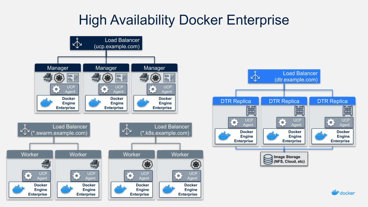
Node Size
A node is a machine in the cluster (virtual or physical) with Mirantis Container Runtime running on it. When adding each node to the cluster, it is assigned a role: MKE manager, MSR replicas, or worker node. Typically, only worker nodes are allowed to run application workloads.
To decide what size the node should be in terms of CPU, RAM, and storage resources, consider the following:
- All MKE manager and worker nodes should fulfill the minimal requirements, the recommended requirements are preferred for a production system, in the MKE system requirements document.
- All MSR replica nodes should fulfill the minimal requirements, the recommended requirements are preferred for a production system, in the MSR system requirements document.
- Ideal worker node size will vary based on your workloads, so it is impossible to define a universal standard size.
- Other considerations like target density (average number of containers per node), whether one standard node type or several are preferred, and other operational considerations might also influence sizing.
If possible, node size should be determined by experimentation and testing actual workloads, and they should be refined iteratively. A good starting point is to select a standard or default machine type in your environment and use this size only. If your standard machine type provides more resources than the MKE Controllers need, it makes sense to have a smaller node size for these. Whatever the starting choice, it is important to monitor resource usage and cost to improve the model.
Two example scenarios:
Homogeneous Node Sizing
- All Node Types
- 4 vCPU
- 16 GB RAM
- 50 GB storage
Role based Node Sizing
- MKE Manager
- 4 vCPU
- 16 GB RAM
- 100 GB storage
- MSR Replica
- 4 vCPU
- 32 GB RAM
- 100 GB storage
- MKE Worker
- 4 vCPU
- 64 GB RAM
- 100 GB storage
Depending on your OS of choice, storage configuration for Mirantis Container Runtime might require some planning. Refer to the Docker Enterprise Compatibility Matrix to see what storage drivers are supported for your host OS.
Load Balancer Configuration
Load balancers configuration should be done before installation, including the creation of DNS entries. Most load balancers should work with Docker Enterprise. The only requirements are TCP passthrough and the ability to do health checks on an HTTPS endpoint.
In our example architecture, the three MKE managers ensure MKE
resiliency in case of node failure or reconfiguration. Access to MKE
through the GUI or API is always done using TLS. The load balancer is
configured for TCP pass-through on port 443, using a custom HTTPS health
check at https://<MKE_FQDN>/_ping.
Be sure to create a DNS entry for the MKE host such as
mke.example.com and point it to the load balancer.
The setup for the three MSR replicas is similar to setting up MKE.
Again, use TCP passthrough to port 443 on the nodes. The HTTPS health
check is also similar to MKE at https://<MSR_FQDN>/_ping.
Create a DNS entry for the MSR host such as dtr.example.com and
point it to the load balancer. It is important to keep it as concise as
possible because it will be part of the full name of images. For
example, user_a’s webserver image will be named
dtr.example.com/user_a/webserver:<tag>.
The Swarm application load balancer provides access to an application’s
HTTP endpoints exposed through MKE’s Layer 7 Routing (Interlock). Layer
7 Routing provides a reverse-proxy to map domain names to services that
expose ports. As an example, the voting application exposes the
vote service’s port 80. Interlock can be leveraged to map
http://vote.apps.example.com to this port, and the application LB
itself maps *.apps.example.com to nodes in the cluster.
For Kubernetes applications as well, a similar approach is used via an ingress controller which provides Layer 7 / proxy capabilities.
For more details on load balancing Swarm and Kubernetes applications on MKE, see the Mirantis Kubernetes Engine Service Discovery and Load Balancing for Swarm and Mirantis Kubernetes Engine Service Discovery and Load Balancing for Kubernetes reference architectures.
MSR Storage
MSR usually needs to store a large number of images. It uses external storage (NFS, Cloud, etc.), not local node storage so that it can be shared between MSR replicas. The MSR replicates metadata and configuration information between replicas, but not image layers themselves. To determine storage size, start with the size of the existing images used in the environment and increase from there.
As long as it is compatible with MSR, it is a good option to use an existing storage solution in your environment. That way image storage can benefit from existing operational experience. If opting for a new solution, consider using object storage, which maps more closely to image registry operations.
Refer to An Introduction to Storage for Docker Enterprise for more information about selecting storage solutions.
Recommendations for the Docker Enterprise Installation
This section details the installation process for the architecture and provide a checklist. It is not a substitute for the documentation, which provides more details and is authoritative in any case. The goal is to help you define a repeatable (and ideally automated) process to deploy, configure, upgrade and expand your Docker Enterprise environment.
The three main stages of a Docker Enterprise installation are as follows:
- Deploying and configuring the infrastructure (hosts, network, storage)
- Installing and configuring the Mirantis Container Runtime, running as an application on the hosts
- Installing and configuring MKE and MSR, delivered as Docker containers running on the hosts
Infrastructure Considerations
The installation documentation details infrastructure requirements for Docker Enterprise. It is recommended to use existing or platform specific tools in your environment to provide standardized and repeatable configuration for infrastructure components.
Network
Docker components need to communicate over the network, and the systems requirements documentation lists the ports used for communication. Misconfiguration of the cluster’s internal network can lead to issues that might be difficult to track down. It is better to start with a relatively simple environment. This reference architecture assumes a single subnet for all nodes and the default settings for all other configuration.
To get more details and evaluate options, consult the Exploring Scalable, Portable Docker Swarm Container Networks reference architecture.
Firewall
Access to Docker Enterprise is done using port 443 and 6443. This makes external firewall configuration simple. In most cases you only need to open ports 443 and 6443. Access to applications is through a load balancer using HTTPS. If you expose other TCP services to the outside world, open those ports on the firewall. As explained in the previous section, several ports need to be open for communication inside the cluster. If you have a firewall between some nodes in the cluster, for example, to separate manager from worker nodes, open the relevant port there as well.
For a full list of ports used see the MKE System Requirements and MSR System Requirements documentation.
If encrypted overlay networks are used within the applications, then ESP (Encapsulating Security Payload) or IP Protocol 50 traffic should also be allowed. ESP is not based on TCP or UDP protocols, and it will be used for end to end encapsulation of security payloads / data.
Load Balancers
Load balancers are detailed in the previous section. They must be in place before installation and must be provisioned with the domain names. External (load balancer) domain names are used for HA and also for TLS certificates. Having everything in place prior to installation simplifies the process as it avoids the need to reconfigure components after the installation process.
Refer to the Load Balancer Configuration section for more details.
Host Configuration
Host configuration varies based on the OS and existing configuration standards, but there are some important steps that must be followed after OS installation:
- Clock synchronization using NTP or similar service. Clock skew can produce hard to debug errors, especially where the Raft algorithm is used (MKE and the MSR).
- Static IPs are required for all hosts.
- Hostnames are used for node identification in the cluster. The hostname must be set in an non-ephemeral way.
- Host firewalls must allow intra-cluster traffic on all the ports specified in the installation docs.
- Storage Driver prerequisite configuration must be completed if required for the selected driver.
Mirantis Container Runtime Installation Considerations
Detailed instructions for the Mirantis Container Runtime installation
are available on the documentation
site. To install on
nodes that do not have internet access, add the package to your internal
package repository or follow the install from package section of the
document for your OS. After installing the package, make sure the
docker service is configured to start on system boot.
The best way to change parameters for Mirantis Container Runtime is to
use the daemon.json configuration file. This ensures that the
configuration can be reused across different systems and OS in a
consistent way. See the dockerd
documentation
for a full list of
options
for the daemon.json configuration file.
Make sure the engine is configured correctly by starting the docker
service and verifying the parameters with docker info.
MKE Installation Considerations
The MKE installer creates a functional cluster from a set of machines running Mirantis Container Runtime. That includes creating a Swarm cluster and installing the MKE controllers. The default installation mode as described in the Install MKE for production document is interactive.
To perform fully-automated, repeatable deployments, provide more information to the installer. The full list of install parameters is provided in the mirantis/ucp install documentation.
Adding Nodes
Once the installation has finished for the first manager node, in order
to enable HA, two additional managers must be installed by joining them
to the cluster. MKE configures a full replica on each manager node in
the cluster, so the only command needed on the other managers is a
docker swarm join with the manager token. The exact command can be
obtained by running docker swarm join-token manager on the first
manager.
To join the worker nodes, the equivalent command can be obtained with
docker swarm join-token worker on any manager:
$ docker swarm join-token worker
To add a worker to this swarm, run the following command (an example):
$ docker swarm join \
   --token SWMTKN-1-00gqkzjo07dxcxb53qs4brml51vm6ca2e8fjnd6dds8lyn9ng1-092vhgjxz3jixvjf081sdge3p \
   192.168.0.2:2377
To make sure everything is running correctly, log into MKE at
https://mke.example.com.
MSR Installation Considerations
Installation of MSR is similar to that of MKE. Install and configure one node, and then join replicas to form a full, highly-available setup. For installation of the first instance as well as the replicas, point the installer to the node in the cluster it will install on.
Certificates and image storage must be configured after installation.
Once shared storage is configured, the two replicas can be added with
the join command.
Validating the Deployment
When installation of everything has finished, tests can be performed to validate the deployment. Disable scheduling of workloads on MKE manager nodes and the MSR nodes.
Basic tests to consider:
- Log in through
https://mke.example.comas well as directly to a manager node, eg.https://manager1.example.com. Make sure the cluster and all nodes are healthy. - Test that you can deploy an application following the example in the documentation.
- Test that users can download a bundle and access the cluster via CLI. Test that they can use compose.
- Test MSR with a full image workflow. Make sure storage is appropriately configured and images are stored in the right place.
Consider building a standard automated test suite to validate new environments and updates. Just testing standard functionality should hit most configuration issues. Make sure you run these tests with a non-admin user, the test user should have similar rights as users of the platform. Measuring time taken by each test can also pinpoint issues with underlying infrastructure configuration. Fully deploying an actual application from your organization should be part of this test suite.
High Availability in Docker Enterprise
In a production environment, it is vital that critical services have minimal downtime. It is important to understand how high availability (HA) is achieved in MKE and MSR, and what to do to when it fails. MKE and MSR use the same principles to provide HA, but MKE is more directly tied to Swarm’s features. The general principle is to have core services replicated in a cluster, which allows another node to take over when one fails. Load balancers make that transparent to the user by providing a stable hostname, independent of the actual node processing the request. It is the underlying clustering mechanism that provides HA.
Swarm
The foundation of MKE HA is provided by Swarm, the clustering functionality of Mirantis Container Runtime. As detailed in the Mirantis Container Runtime documentation, there are two algorithms involved in managing a Swarm cluster: a Gossip protocol for worker nodes and the Raft consensus algorithm for managers. Gossip protocols are eventually consistent, which means that different parts of the cluster might have different versions of a value while new information spreads in the cluster (they are also called epidemic protocols because information spreads like a virus). This allows for very large scale cluster because it is not necessary to wait for the whole cluster to agree on a value, while still allowing fast propagation of information to reach consistency in an acceptable time. Managers handle tasks that need to be based on highly consistent information because they need to make decisions based on global cluster and services state.
In practice, high consistency can be difficult to achieve without impeding availability because each write needs to be acknowledged by all participants, and a participant being unavailable or slow to respond will impact the whole cluster. This is explained by the CAP Theorem, which (to simplify) states that in the presence of partitions (P) in a distributed system, we have to chose between consistency (C) or availability (A). Consensus algorithms like Raft address this trade-off using a quorum: if a majority of participant agree on a value, it is good enough, the minority participant eventually get the new value. That means that a write needs only acknowledgement from 2 out of 3, 3 out of 5, or 4 out of 7 nodes.
Because of the way consensus works, an odd number of nodes is recommended when configuring Swarm. With 3 manager nodes in Swarm, the cluster can temporarily lose 1 and still have a functional cluster, with 5 you can lose 2, and so on. Conversely, you need 2 managers to acknowledge a write in a 3 manager cluster, but 3 with 5 managers, so more managers do not provide more performance or scalability — you are actually replicating more data. Having 4 managers does not add any benefits since you still can only lose 1 (majority is 3), and more data is replicated than with just 3. In practice, it is more fragile.
If you have 3 managers and lose 2, your cluster is non-functional. Existing services and containers keep running, but new requests are not processed. A single remaining manager in a cluster does not “switch” to single manager mode. It is just a minority node. You also cannot just promote worker nodes to manager to regain quorum. The failed nodes are still members of the consensus group and need to come back online.
MKE
MKE runs a global service across all cluster nodes called ucp-agent.
This agent installs a MKE controller on all Swarm manager nodes. There
is a one-to-one correspondence between Swarm managers and MKE
controllers, but they have different roles. Using its agent, MKE relies
on Swarm for HA, but it also includes replicated data stores that rely
on their own raft consensus groups that are distinct from Swarm:
ucp-auth-store, a replicated database for identity management data, and
ucp-kv, a replicated key-value store for MKE configuration data.
MSR
The MSR has a replication model that is similar to how MKE works, but it does not synchronize with Swarm. It has one replicated component, its datastore, which might also have a lot of state to replicate at one time. It relies on raft consensus.
Both MKE controllers and MSR replicas may have a lot more state to replicate when (re)joining the cluster. Some reconfiguration operations can make a cluster member temporary unavailable. With 3 members, it is good practice to wait for the one you reconfigured to get back in sync before reconfiguring a second one, or they could lose quorum. Temporary losses in quorum are easily recoverable, but it still means the cluster is in an unhealthy state. Monitoring the state of controllers to ensure the cluster does not stay in that state is critical.
Backup and Restore
The HA setup using multiple nodes works well to provide continuous availability in the case of temporary failure, including planned node downtime for maintenance. For other cases, including the loss of the full cluster, permanent loss of quorum, and data loss due to storage faults, restoring from backup is necessary.
MKE Backup
A backup of MKE is obtained by running the mirantis/ucp backup command
on a manager node. It stops the MKE containers on the node and performs
a full backup of the configuration and state of MKE. Some of this
information is sensitive, therefore it is recommended to use the
--passphrase option to encrypt the backup. The backup also includes
information about organizations, teams and users used by MKE as well as
MSR. It is highly recommended to schedule regular backups. Here is an
example showing how to run the mirantis/ucp backup command without
user interaction:
$ UCPID=$(docker run --rm -i --name ucp -v /var/run/docker.sock:/var/run/docker.sock docker/ucp id)
$ docker run --rm -i --name ucp -v /var/run/docker.sock:/var/run/docker.sock docker/ucp backup \
    --id $UCPID --passphrase "secret" > /tmp/backup.tar
There are two ways to use the backup: - To restore a controller using
the mirantis/ucp restore command (only the backup from that controller
can be used) - To install a new cluster using the
docker/ucp install --from-backup command (preserves users and
configuration)
MSR Backup
A MSR backup includes configuration information, images metadata, and certificates. Images themselves need to be backed up separately directly from storage. Remember that users and organizations within MSR are managed and backed up by MKE.
The backup can only be used to create a new MSR, using the
mirantis/dtr restore command.
Identity Management
Accessing resources (images, containers, volumes, networks etc) and functionality within the components of Docker Enterprise (MKE & MSR) require at a minimum, an account and a corresponding password to be accessed. Accounts within Docker Enterprise are identities stored within an internal database, but the source of creating those accounts and the associated access control can be manual (managed or internal) or external through a connection to a directory server (LDAP) or Active Directory (AD). Managing the authorization for these accounts is an extension of coarse and fine grained permissions that are described in the sections below.
RBAC and Managing Access to Resources
MKE provides powerful role based access control features which can be seamlessly integrated with enterprise identity management tool sets and address enterprise security requirements. Besides facilitating both coarse-grained and fine-grained security access controls, this feature can be used as an enabler of multi-tenancy within a single MKE cluster sharing a wide range of resources grouped into collections.
Access permissions in MKE are managed through grants of roles to subjects over collections of those resources. Access permissions are what define what a user can or cannot do within the system.
The default roles in MKE are None, View Only,
Restricted Control, Scheduler, and Full Control. The
description about these roles and how they relate to each other are
detailed in the Securing Docker Enterprise and Security Best Practices reference architecture.
Each of these roles have a set of operations that define the permissions
associated with the role. Additional custom roles can be defined by
combining a unique set of permissions. Custom roles can be leveraged to
accommodate fine-grained access control as required for certain
organizations and security controls.
Subjects are individual users or teams within an organization. Teams are typically backed by an LDAP/AD group or search filter. It is also possible to add users manually. But it is not possible to have a hybrid composition of users. In other words, the list of users within a team should be derived from a directory server (e.g. AD) or should be added manually, not both.
Collections are groupings of objects within MKE. A collection can be
made up of one or many of nodes, stacks, containers, services, volumes,
networks, secrets, or configs — or it can hold other collections. To
associate a node or a stack or any resource with a collection, that
resource should share the label com.docker.ucp.access.label with the
collection. A resource can be associated with zero or multiple
collections, and a collection can have zero or multiple resources or
other child collections in it. Collections within collections allow the
structuring of resource objects in a hierarchical nature and can
significantly simplify access control. Access provided at a top level
collection is inherited by all its children, including any child
collections.
Consider a very simple use case for this approach. Suppose you define a
top level collection called Prod and additional child collections
corresponding to each application within Prod. These child
collections contain the actual resource objects for the application like
stacks, services, containers, volumes, networks, secrets, etc. Now
suppose that all members of the IT Operations team require access to all
Prod resources. With this setup, even if there are a high number of
applications (and by extension, child collections within the Prod
collection), the team IT Operations within MKE can be granted access
to the Full Control role over the Prod collection alone. The
access trickles down to every collection contained within the Prod
collection. At the same time, members of a specific application
development team can be provided fine-grained access to just the
application collection. This model implements a traditional Role Based
Access Control (RBAC), where the teams are assigned roles over specific
collections of resources.
Managed (Internal) Authentication
Managed mode for authentication and authorization is the default mode in Docker Enterprise. In this mode, accounts are directly created using the Docker Enterprise API. User accounts can be created manually by accessing the User Management —> Users —> Create User form in the MKE UI. Accounts can also be created and managed in an automated fashion by making HTTP requests to the authentication and authorization RESTful service known as eNZi.
User management using the “Managed” mode is recommended only for demo purposes or where the number of users needing to access Docker Enterprise is very small.
Pros:
- Easy and quick to setup
- Simple to troubleshoot
- Appropriate for a small set of users with static roles
- Managed without leaving the MKE interface
Cons:
- User Account management gets cumbersome for larger numbers or when roles need to be managed for several applications.
- All lifecycle changes such as adding / removing permissions of users need to be accomplished manually user by user.
- Users must be deleted manually, meaning access may not get cleaned up quickly, making the system less secure.
- Sophisticated setups of integrating application creation and deployment through LDAP or external systems is not possible.
LDAP / AD Integration
The LDAP method of user account authentication can be turned on to manage user access. As the name suggests, this mode enables automatic synchronization of user accounts from a directory server such as Active Directory or OpenLDAP.
This method is particularly applicable for enterprise use cases where organizations have a large set of users, typically maintained in a centralized identity store that manages both authentication and authorization. Most of these stores are based on a directory server such as Microsoft’s Active Directory or a system that supports the LDAP protocol. Additionally, such enterprises already have mature processes for on-boarding, off-boarding, and managing the lifecycle of changes to user and system accounts. All these can be leveraged to provide a seamless and efficient process of access control within Docker Enterprise.
Pros:
- Ability to leverage already-established access control processes to grant and revoke permissions
- Ability to continue managing users and permissions from a centralized system based on LDAP
- Ability to take advantage of self-cleaning nature of this mode, where non-existent LDAP users are automatically removed from Docker Enterprise on the next sync, thereby increasing security
- Ability to configure complex, upstream systems such as flat files, database tables using an LDAP proxy, and the automatic time-based de-provisioning of access through AD/LDAP groups
Cons:
- Increased complexity compared to Managed mode
- Higher admin requirements since knowledge on an external system (LDAP) is needed
- Greater time needed to troubleshoot issues with an extra component (LDAP) in the mix
- Unexpected changes to Docker Enterprise due to changes made to upstream LDAP/AD systems, which can have unexpected effects on Docker Enterprise
A recommended best practice is to use group membership to control the access of user accounts to resources. Ideally, the management of such group membership is achieved through a centralized Identity Management or a Role Based Access Control system. This provides a standard, flexible, and scalable model to control the authentication and authorization rules within Docker Enterprise through a centralized directory server. Through the Identity Management system, this directory server is kept in sync with user on-boarding, off-boarding, and changes in roles and responsibilities.
To change the mode of authentication, use the form at Admin Settings —> Authentication & Authorization in the MKE UI. In this form, set the LDAP Enabled toggle to Yes.
Accounts that are discovered and subsequently synced from the directory server can be automatically assigned default permissions on their own private collections. To assign additional permissions on non-private collection, those users need to be added to appropriate teams that have the required role(s) assigned.
For details about the LDAP configuration options, refer to the Integrate with an LDAP directory documentation.
The following list highlights important configuration options to consider when setting up LDAP authentication:
- In LDAP auth mode, when accounts are discovered, they may not get created within MKE until after the users log into the system. This is controlled by the Just-in-time User Provisioning setting in the LDAP configuration. It is recommended to turn on this setting.
- A user account on the directory server has to be configured to
discover and import accounts from the directory server. This user
account is recommended to have read-only to view the necessary
organizationalUnits (
ou) and query for group memberships. The details for this account are configured using the fields Reader DN and Reader Password. The Reader DN must be in the distinguishedName format. - Use secure LDAP if at all possible.
- Use the LDAP Test Login section of the LDAP configuration to make sure you can connect before switching to LDAP authentication.
- Once the form is filled out and the test connection succeeds, the sync button provides an option to run a sync immediately without waiting for the next interval. Doing so initiates an LDAP connection and runs the filters to import the users.
- After the configuration is complete and saved, it should be possible to log in using a valid LDAP/AD account that matched the sync criteria. The account should be active within the LDAP/AD system for the login to be successful within Docker Enterprise.
- The progress / status of the sync and any errors that occur can be viewed and analyzed in the LDAP Sync Jobs section.
Organizations & Teams
User accounts that exist within Docker Enterprise, either through a LDAP sync or manually managed, can be organized into teams. Teams need to be contained within an Organization. Each team created can be granted a role on collections that will allow the members of the team to operate within the associated collection.
Consider this example of creating an organization called
enterprise-applications with three teams Developers, Testers
and Operations.
To create a team, an organization needs to be created first. An organization can be created under Access Control —> Orgs & Teams by clicking the Create button.
Teams can be created in the MKE UI by clicking on an organization and
then clicking on + on the upper right side of the page. Once a team
is created, members can be added to the team manually or synchronized
via LDAP groups. This is based on an automatic sync of discovered
accounts from the directory server that was configured to enable the
LDAP Auth mode. Finer filters can be applied here which determine which
discovered accounts are placed into which teams. A team can have
multiple users, and a user can be a member of zero to multiple teams.
Below is an example of creating three teams Developers, Testers
and Operations inside the enterprise-applications organization.
First, create the enterprise-applications organization:
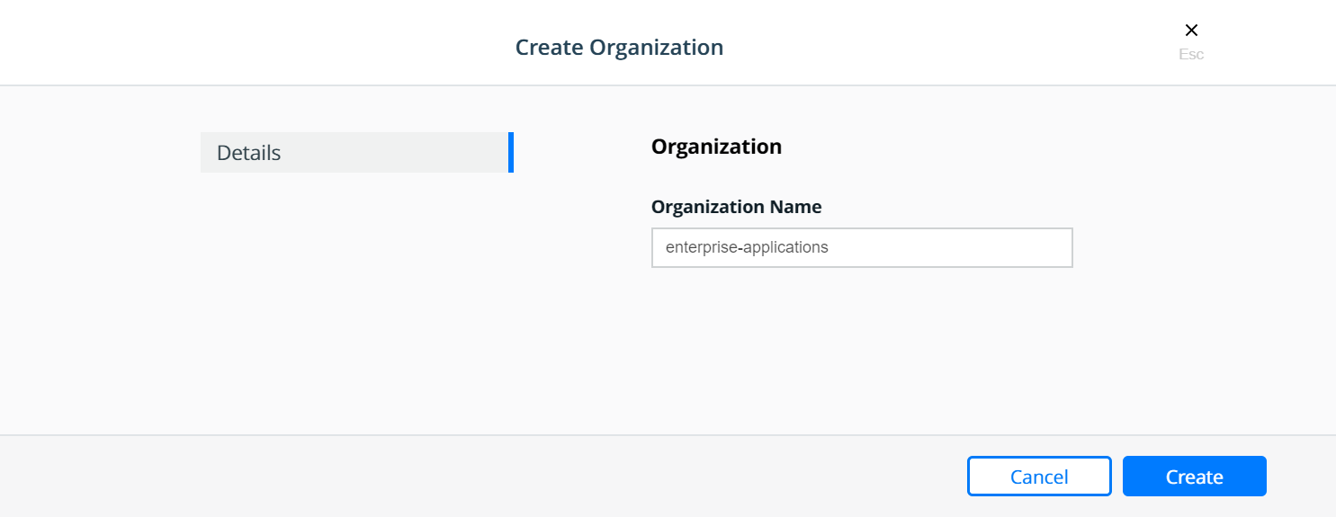
Select the enterprise-applications organization:
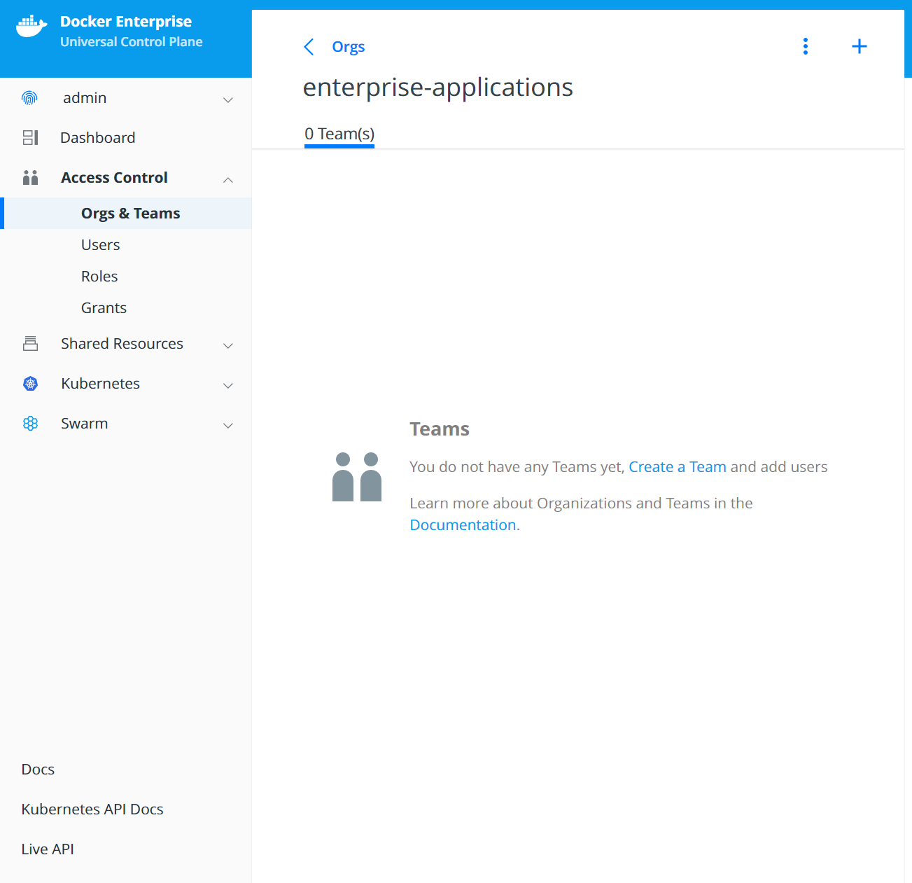
Create the Developers team:
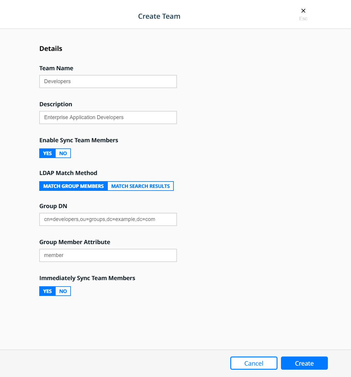
Create the Testers team:
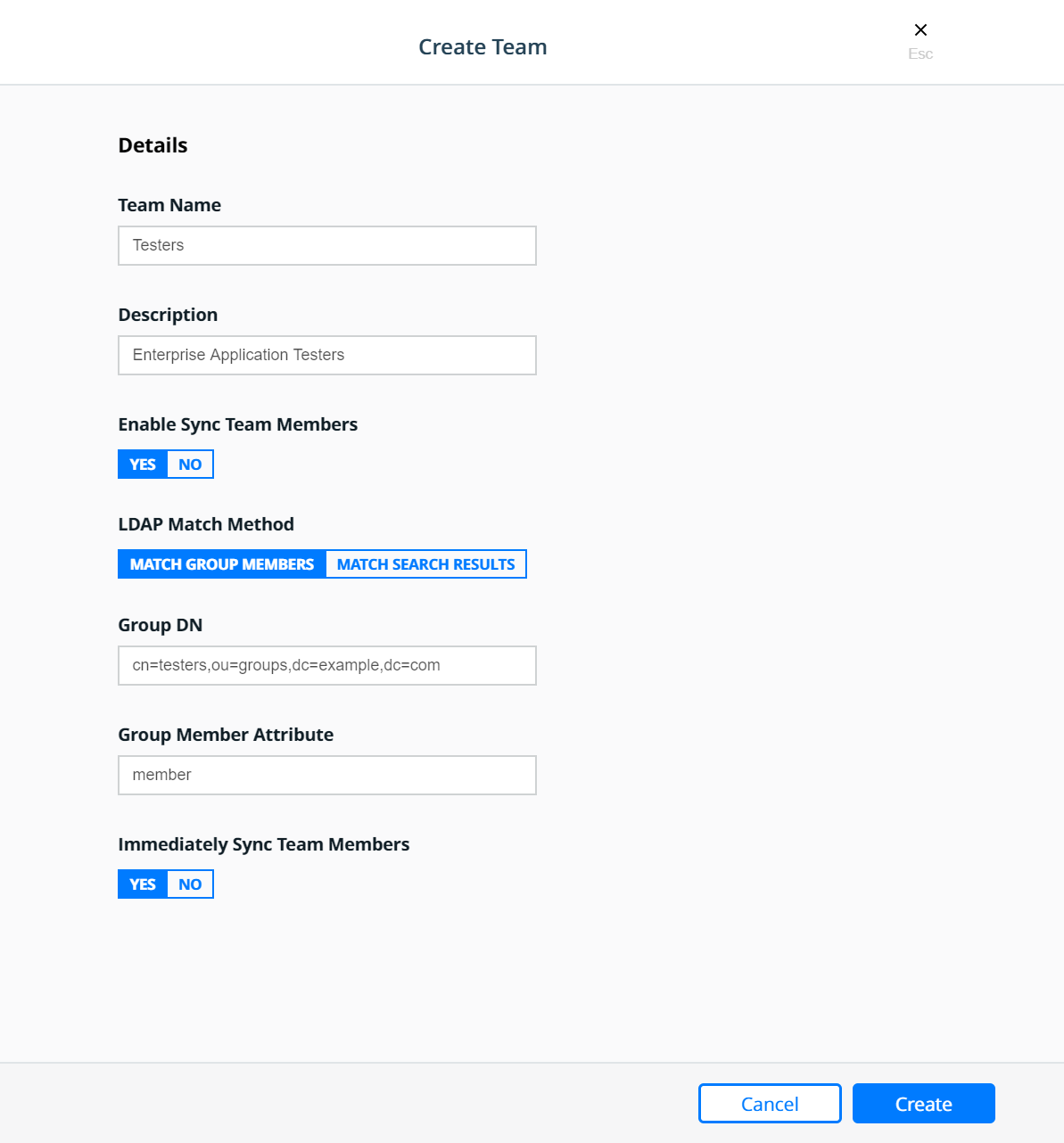
Create the Operations team:

Resource Sets
To control user access, cluster resources are grouped into Kubernetes namespaces or Docker Swarm collections.
Kubernetes namespaces: A namespace is a logical area for a Kubernetes cluster. Kubernetes comes with a default namespace for your cluster objects, plus two more namespaces for system and public resources. You can create custom namespaces, but unlike Swarm collections, namespaces cannot be nested. Resource types that users can access in a Kubernetes namespace include pods, deployments, network policies, nodes, services, secrets, and many more.
Swarm collections: A collection has a directory-like structure that holds Swarm resources. You can create collections in MKE by defining a directory path and moving resources into it. Also, you can create the path in MKE and use labels in your YAML file to assign application resources to the path. Resource types that users can access in a Swarm collection include containers, networks, nodes, services, secrets, and volumes.
Together, namespaces and collections are named resource sets. For more information, see the Resource Set documentation.
Kubernetes Namespaces
A namespace is a scope for Kubernetes resources within a cluster. Kubernetes comes with a default namespace for your cluster objects, plus two more namespaces for system and public resources. You can create custom namespaces, but unlike Swarm collections, namespaces cannot be nested. Resource types that users can access in a Kubernetes namespace include pods, deployments, network policies, nodes, services, secrets, and many more.
Namespaces can be found in MKE under Kubernetes —> Namespaces.
To create a new namespace click the Create button which will bring
up the Create Kubernetes Object panel. On the Create Kubernetes
Object panel you can either enter the YAML directly or upload an
existing YAML file. For more information about Kubernetes namespace see
the Share a Cluster with
Namespaces
documentation. Below is an example of creating a namespace called
prod-billing-application.
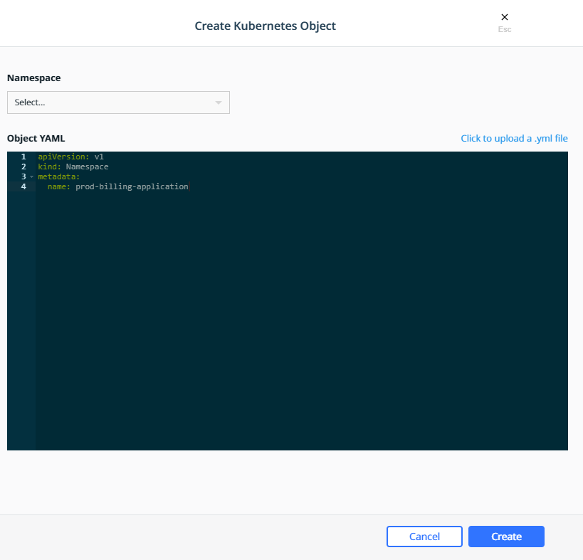
Once a namespace has been created, a Role Binding can be created to assign a role to users, teams, or service accounts based on the functions they need to perform.
Swarm Collections
A collection is a logical construct that can be used to group a set of
resources. Collection are found under Shared Resources —>
Collections. The Swarm collection is the root collections and
all collections must be created as a child of the Swarm collection.
To create a collections first click View Children next to the
Swarm collection. Then click the Create Collections on the upper
right of the page. Below is an example of creating a collection called
Production.
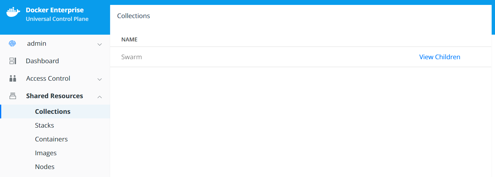
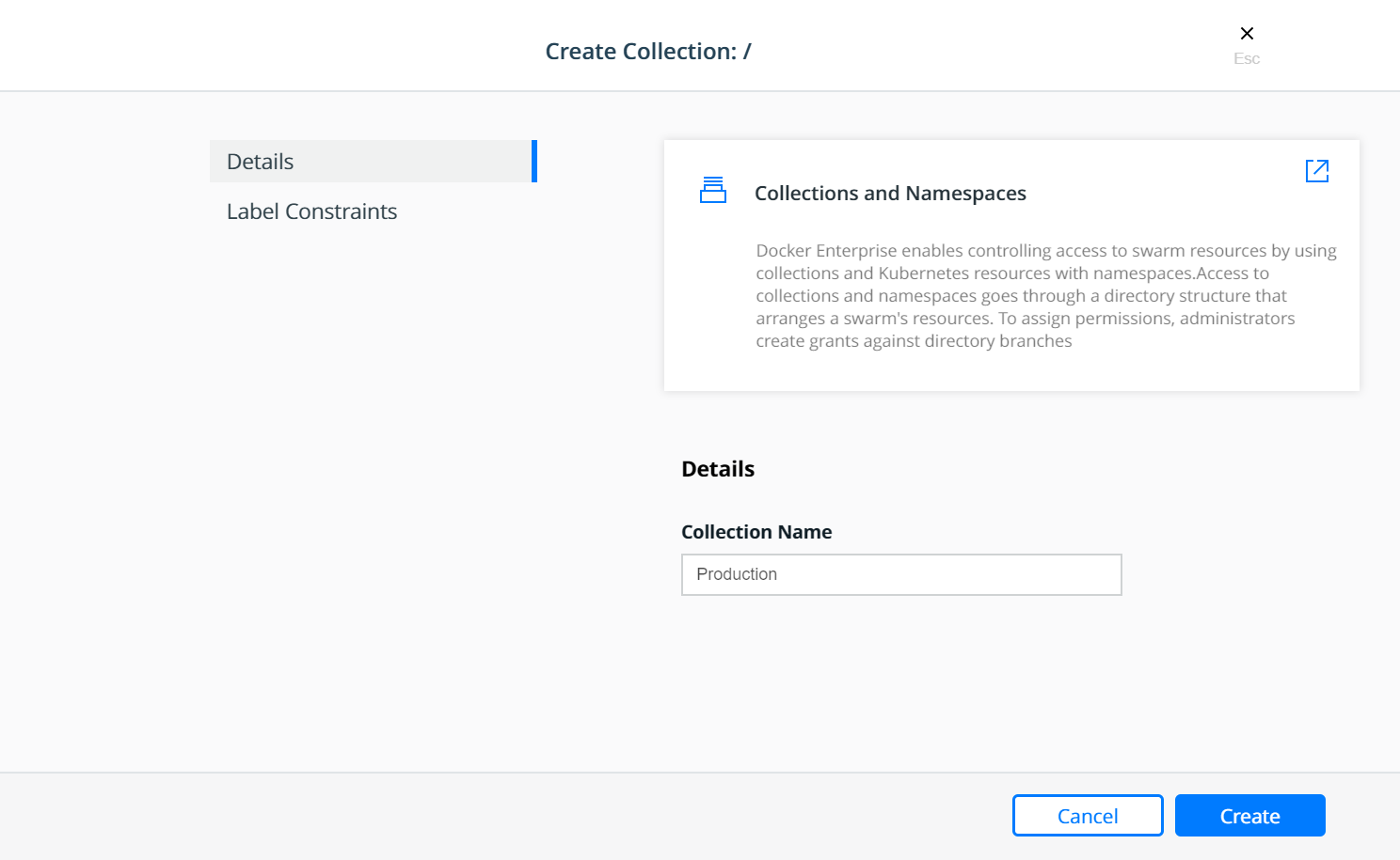
The Production collection in this example is used to hold other
application collections. One such collection is the
Billing Application which can be created as a child of the
Production collection. To Create the Billing Application
navigate to Shared Resources —> Collections —> click View
Children next to the Swarm collection —> click View Children
next to the Production collection and then click the Create
Collections on the upper right of the page.
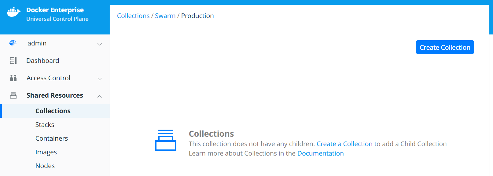
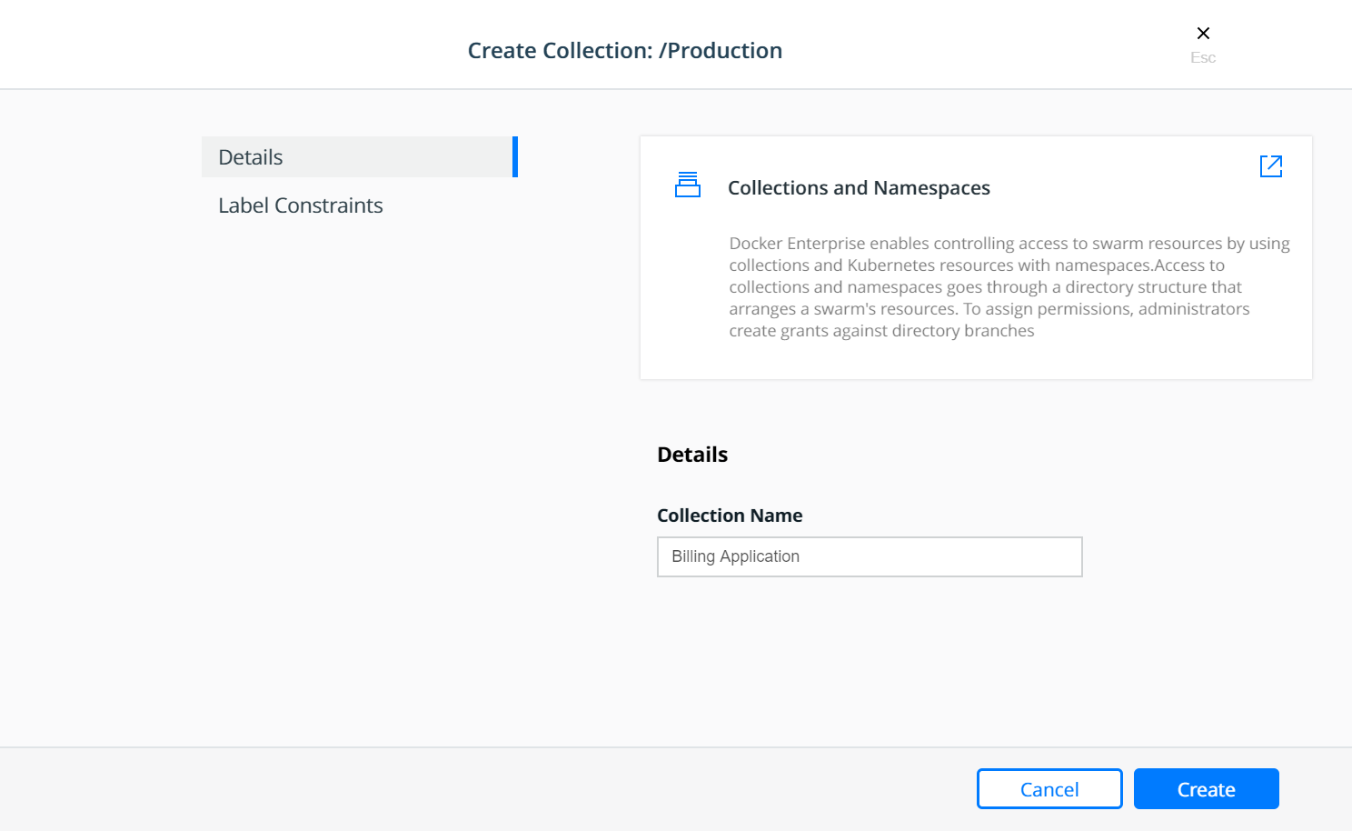
At this point, a grant can be created to assign a role to the teams based on their functions within the collection(s).
Grants
Docker Enterprise administrators can create grants to control how users and organizations access resource sets.
A grant defines who has how much access to what resources. Each grant is a 1:1:1 mapping of subject, role, and resource set. A common workflow for creating grants has four steps:
- Add and configure subjects (users, teams, and service accounts).
- Define custom roles (or use defaults) by adding permitted API operations per type of resource.
- Group cluster resources into a resource set.
- Create grants by combining subject + role + resource set.
It is easier to explain with a real world example:
Suppose you have a simple application called www, which is a web
server based on the nginx official image. Also suppose that the
www application is one of the billing applications deployed into
production. There are three teams that need access to this application —
Developers, Testers, and Operations. Typically, Testers
need view only access and nothing more, while the Operations team
would need full control to manage and maintain the environment. The
Developers team needs access to troubleshoot, restart, and control
the lifecycle of the application but should be forbidden from any other
activity involving the need to access the host file systems or starting
up privileged containers. This follows a typical use case that uses the
principles of “least privilege / permission” as well as “separation of
duties.”
The following sections will address the access requirements of the
example application www described above for each orchestrator.
Kubernetes Role Bindings
Kubernetes Role Bindings can be created in MKE using the wizard by navigating to Access Control —> Grants —> Swarm tab —> Create Role Binding.
First create a role binding to provide the enterprise-applications
Operations team with the admin role on the
prod-billing-application namespace.
Select the organization enterprise-applications and team
Operations for the Subject:
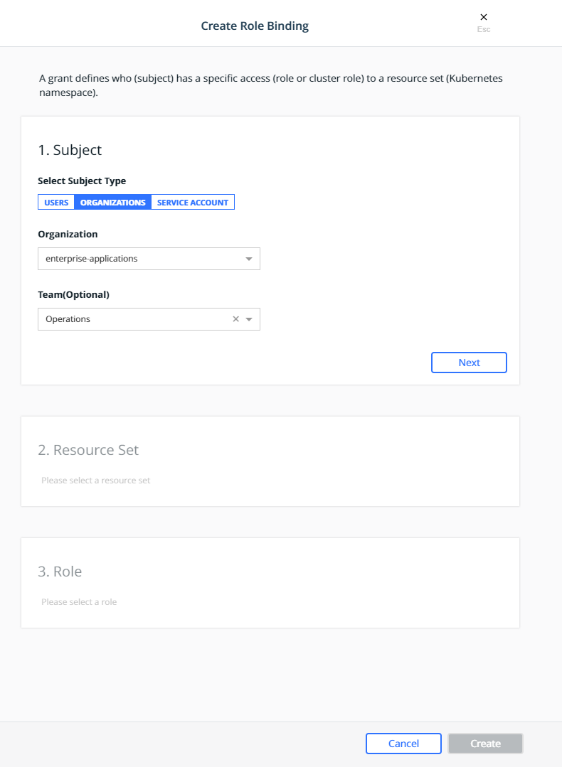
Click Next.
Select the prod-billing-application namespace for the Resource Set:
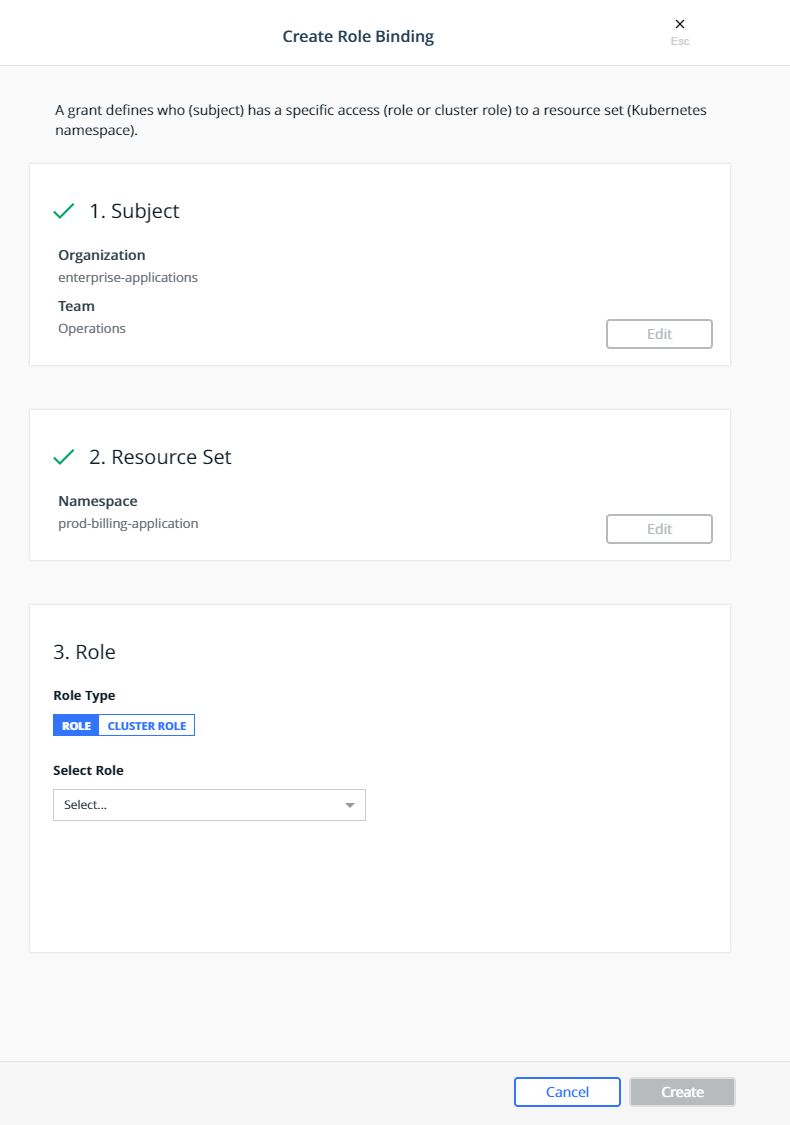
Select the Cluster Role for the Role Type and admin for the
Cluster Role:
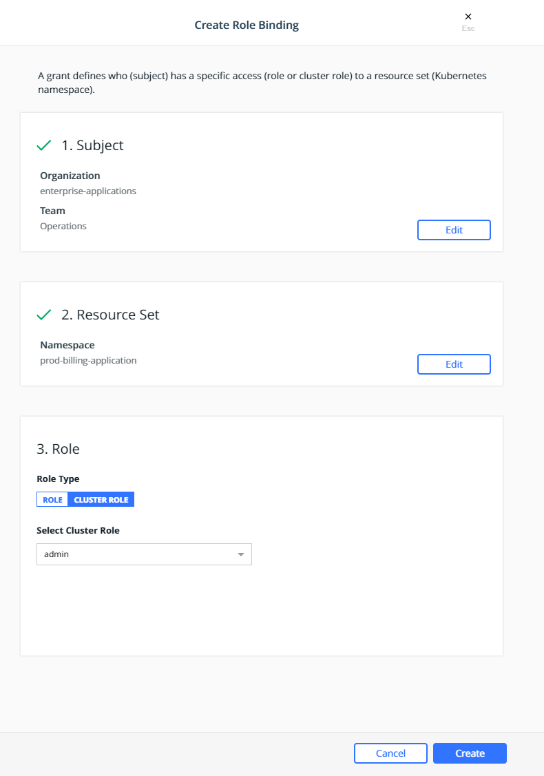
Click Create.
This will create a role binding
enterprise-applications-Operations:admin on the
prod-billing-application namespace.
Create two more role binding, using the same steps above, for the remaining teams:
- Select the
enterprise-applicationsDevelopersteam for the subject, select theprod-billing-applicationnamespace for the resource set, selectCluster Rolefor the Role Type andeditfor the Cluster Role. - Select the
enterprise-applicationsTestersteam for the subject, select theprod-billing-applicationnamespace for the resource set, selectCluster Rolefor the Role Type andviewfor the Cluster Role.
With these role bindings, the teams would have appropriate levels of
access based on their functions to any resources within the
prod-billing-application namespace.
To associate the www resources with the prod-billing-application
namespace, the resources are created in the usual manner, except the
namespace is selected before creating the resources as show below:
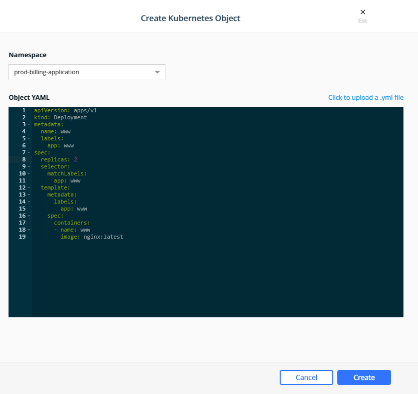
Swarm Grants
Swarm grants can be created in MKE using the wizard by navigating to Access Control —> Grants —> Swarm tab —> Create Grant.
First create a grant to provide the enterprise-applications
Operations team with Full Control of the Production
collection.
Select the organization enterprise-applications and team
Operations for the Subject:
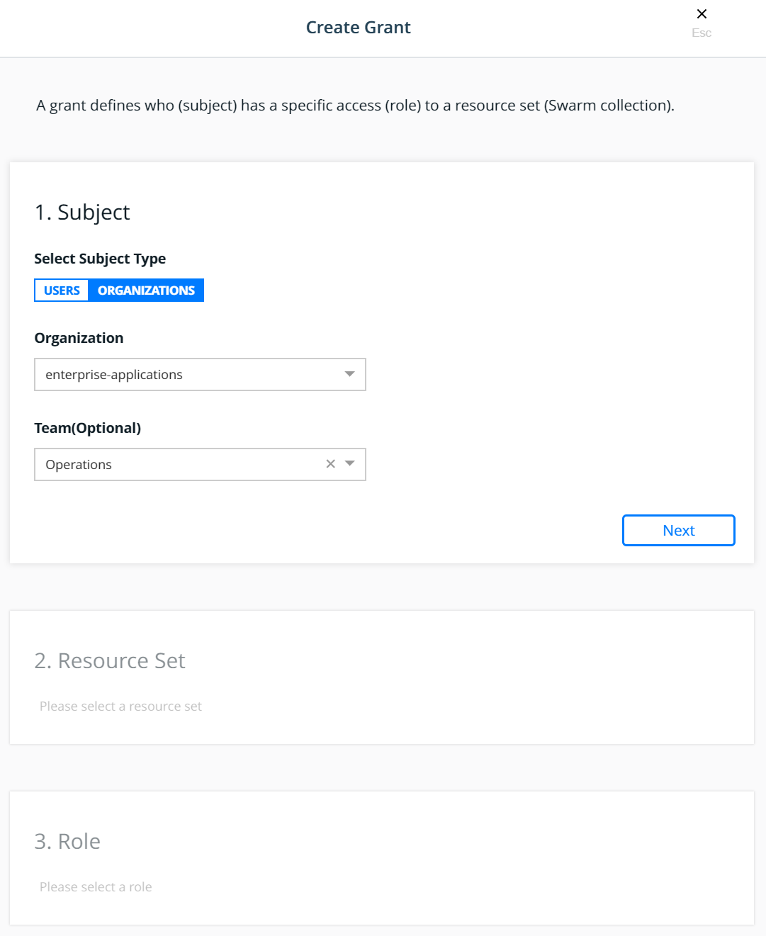
Click Next.
Select the Production collection for the Resource Set:
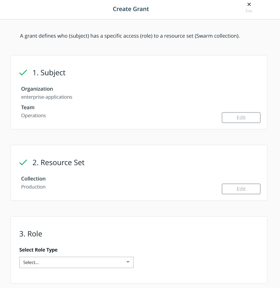
Select the Full Control role type for the Role:
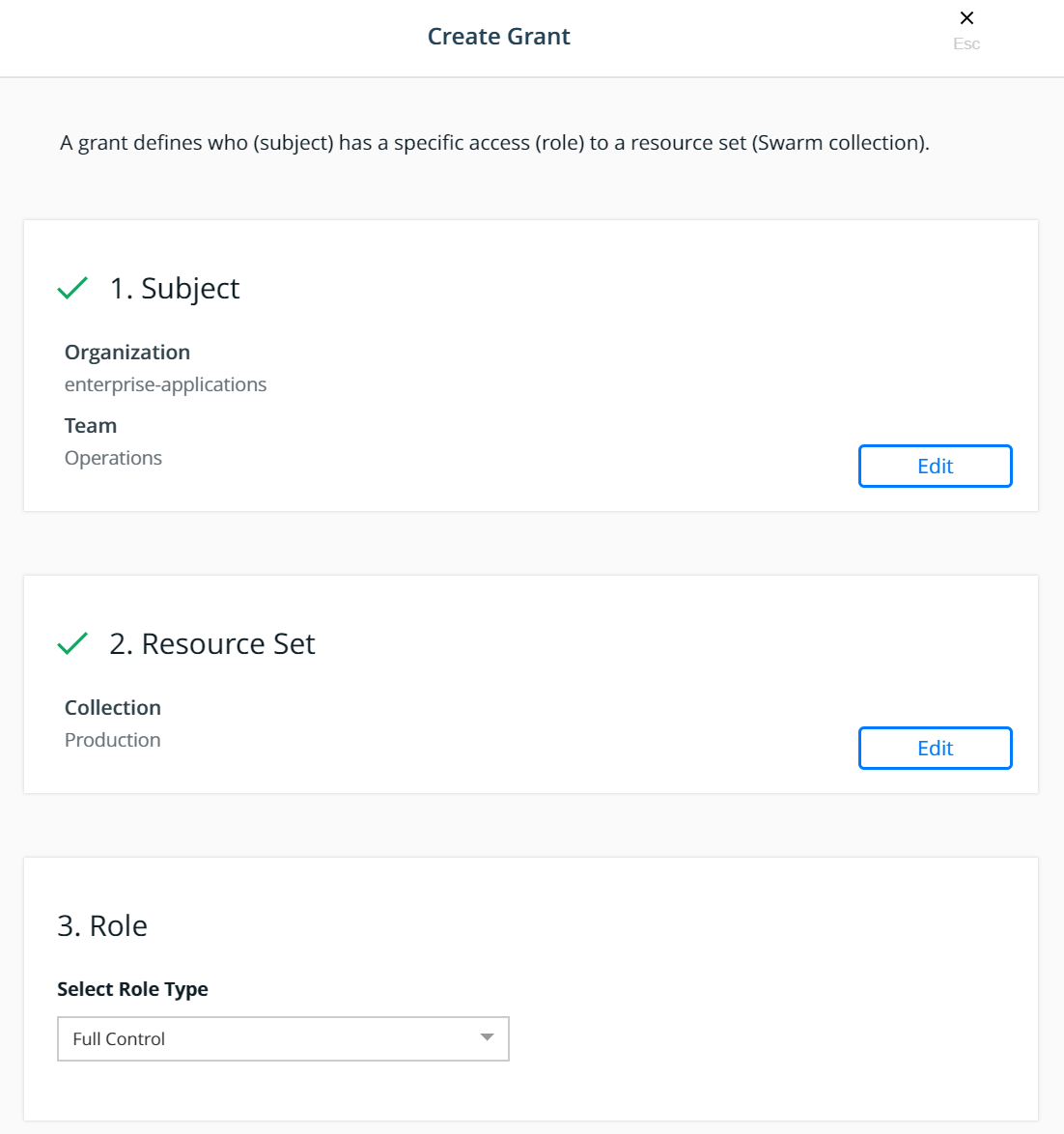
Click Create.
This will create a grant for Team - Operations, Full Control,
/Production
Create two more grant, using the same steps above, for the remaining teams:
- Select the
enterprise-applicationsDevelopersteam for the subject, select theBilling Applicationcollection for the resource set, and select theRestricted Controlrole type for the role. - Select the
enterprise-applicationsTestersteam for the subject, select theBilling Applicationcollection for the resource set, and select theView Onlyrole type for the role.
With these grants, the teams would have appropriate levels of access
based on their functions to any application within the
Billing Application collection.
To associate the www application with the Billing Application
collection, the service is created in the usual manner, except the
collection is selected before creating the service as show below:
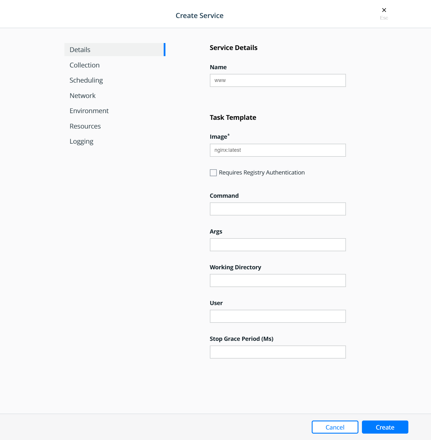
Select the collection:
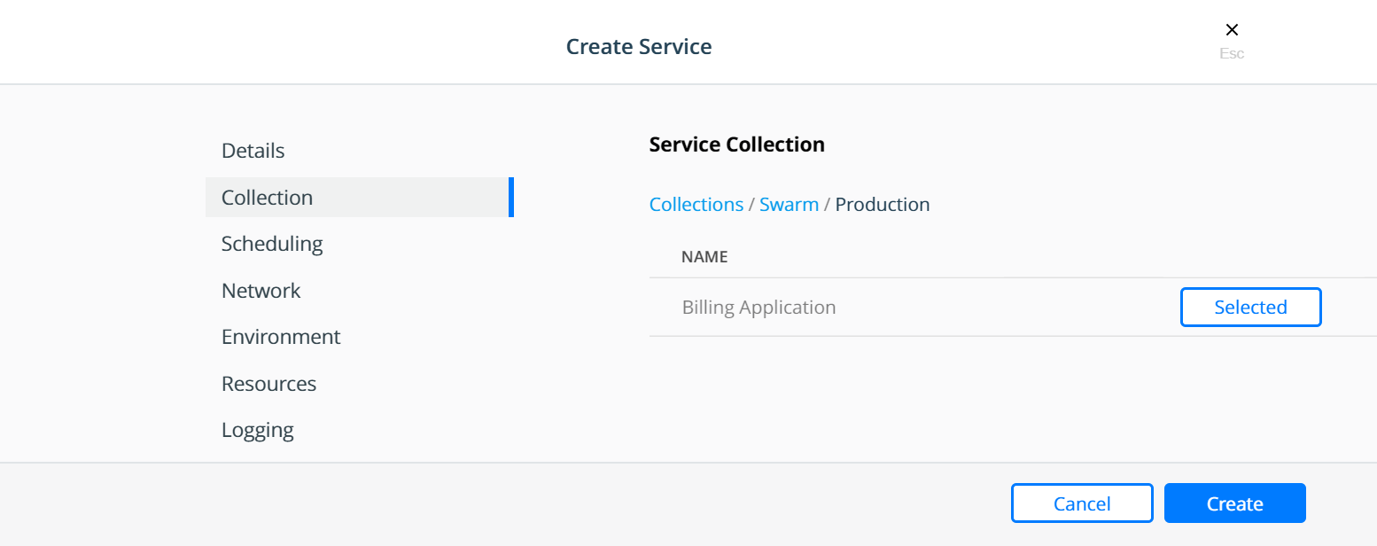
Strategy for Using LDAP Filters
The users needing access to MKE are all sourced from the corporate Directory Server system. These users are the admin users needed to manage the Docker Enterprise infrastructure as well as all members of each of the teams configured within MKE. Also assume that the total universe of users needing access to Docker Enterprise (includes admins, developers, testers, and operations) is a subset of the gamut of users within the Directory Server.
A recommended strategy to use when organizing users is to create an
overarching membership group that identifies all users of Docker
Enterprise, irrespective of which team they are a part of. Let us call
this group Docker_Users. No user should be made a member of this
group directly. Instead, the Docker_Users group should contain other
groups and only those other groups as its members. Per our example, let
us call these groups dev, test, and ops. In our example,
these groups are part of what is known as a nested group structure
within the directory server. Nested groups allow the inheritance of
permissions from one group to each of its sub-groups.
NOTE: Some directory servers do not support the feature of nested groups or even thememberOfattribute by default. If so, then they would need to be enabled. If the choice of directory server does not support these features at all, then alternate means of organizing users and querying them should be used. Microsoft Active Directory supports both these features out of the box.
User accounts should be added as members of these sub-groups in the directory server. This should not impact any existing layout in the organization units or pre-existing group membership for these users. The sub-group should be used as the value of the Group DN in the defining of the teams.
Finally, if and when it becomes necessary to terminate all access for
any user account, removing the group membership of the account from just
the one group Docker_Users would remove all access for the user. Due
to the nature of how nested groups work, all additional access within
Docker is automatically cleaned — the user account is removed from any
and all team memberships at the time of the next sync without need for
manual intervention or additional steps. This step can be integrated
into a standard on-boarding / off-boarding automated provisioning step
within a corporate Identity Management system.
Authentication API (eNZi)
The AuthN API or eNZi (as it is known internally and pronounced N-Z) is a centralized authentication and authorization service and framework for Docker Enterprise. This API is completely integrated and configured into Docker Enterprise and works seamlessly with MKE as well as MSR. This is the component and service under the hood that manages accounts, teams and organizations, user sessions, permissions and access control through labels, Single-Sign-On (Web SSO) through OpenID Connect, and synchronization of account details from an external LDAP-based system into Docker Enterprise.
For regular day-to-day activities, users and operators need not be concerned with the AuthN API and how it works. However, its features can be leveraged to automate many common functions and/or bypass the MKE UI altogether to manage and manipulate the data directly.
Interaction with AuthN can be accomplished in two ways: via the exposed
RESTful AuthN API over HTTP or via the enzi command.
For example, the command below uses curl and jq to fetch all
user accounts in Docker Enterprise via the AuthN API over HTTP:
$ curl --silent --insecure --header "Authorization: Bearer $(curl --silent --insecure \
     --data '{"username":"<admin-username>","password":"<admin-password>"}' \
    https://<UCP-domain-name>/auth/login | jq --raw-output .auth_token)" \
    https://<UCP-domain-name>/enzi/v0/accounts | jq .
The AuthN service can also be invoked on the CLI on a MKE controller. To connect into it, run the following on a MKE controller:
$ docker exec -it ucp-auth-api sh
At the resulting prompt (#), type the enzi command with a
sub-command such as the one below to list the database table status:
$ enzi db-status
See also
Refer to Recovering the Admin Password for Docker Enterprise for a detailed example.
Warning
Mirantis stopped maintaining this documentation set as of 2021-07-21, in correlation with the End of Life date for MKE 3.2.x and MSR 2.7.x. The company continues to support MCR 19.03.x and its documentation.
For the latest MKE, MSR, and MCR product documentation, refer to:
Networking
Discover how to design Docker networks while considering the constraints of the application and the physical network.
Exploring Scalable, Portable Docker Swarm Container Networks
Introduction
Docker containers wrap a piece of software in a complete filesystem that contains everything needed to run: code, runtime, system tools, system libraries – anything that can be installed on a server. This guarantees that the software will always run the same, regardless of its environment. By default, containers isolate applications from one another and the underlying infrastructure, while providing an added layer of protection for the application.
What if the applications need to communicate with each other, the host, or an external network? How do you design a network to allow for proper connectivity while maintaining application portability, service discovery, load balancing, security, performance, and scalability? This Document is an overview of the architecture and design concepts with which to build and scale Docker container networks for both Linux and Microsoft servers.
Prerequisites
Before continuing, being familiar with Docker concepts and Docker Swarm is recommended:
Challenges of Networking Containers and Microservices
Microservices practices have increased the scale of applications which has put even more importance on the methods of connectivity and isolation provided to applications. The Docker networking philosophy is application driven. It aims to provide options and flexibility to the network operators as well as the right level of abstraction to the application developers.
Like any design, network design is a balancing act. Docker Enterprise and the Docker ecosystem provide multiple tools to network engineers to achieve the best balance for their applications and environments. Each option provides different benefits and tradeoffs. The remainder of this guide details each of these choices so network engineers can understand what might be best for their environments.
Docker has developed a new way of delivering applications, and with that, containers have also changed some aspects of how networking is approached. The following topics are common design themes for containerized applications:
- Portability
- How do I guarantee maximum portability across diverse network environments while taking advantage of unique network characteristics?
- Service Discovery
- How do I know where services are living as they are scaled up and down?
- Load Balancing
- How do I spread load across services as services themselves are brought up and scaled?
- Security
- How do I segment to prevent the wrong containers from accessing each other?
- How do I guarantee that a container with application and cluster control traffic is secure?
- Performance
- How do I provide advanced network services while minimizing latency and maximizing bandwidth?
- Scalability
- How do I ensure that none of these characteristics are sacrificed when scaling applications across many hosts?
The Container Networking Model
The Docker networking architecture is built on a set of interfaces called the Container Networking Model (CNM). The philosophy of CNM is to provide application portability across diverse infrastructures. This model strikes a balance to achieve application portability and also takes advantage of special features and capabilities of the infrastructure.
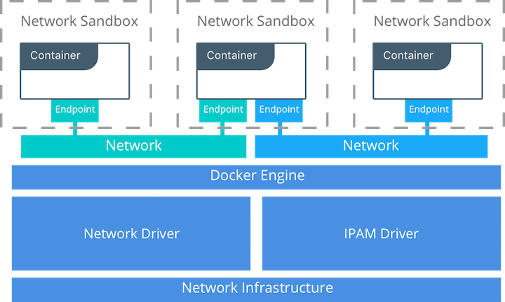
CNM Constructs
There are several high-level constructs in the CNM. They are all OS and infrastructure agnostic so that applications can have a uniform experience no matter the infrastructure stack.
- Sandbox — A Sandbox contains the configuration of a container’s network stack. This includes the management of the container’s interfaces, routing table, and DNS settings. An implementation of a Sandbox could be a Windows HNS or Linux Network Namespace, a FreeBSD Jail, or other similar concept. A Sandbox may contain many endpoints from multiple networks.
- Endpoint — An Endpoint joins a Sandbox to a Network. The Endpoint construct exists so the actual connection to the network can be abstracted away from the application. This helps maintain portability so that a service can use different types of network drivers without being concerned with how it’s connected to that network.
- Network — The CNM does not specify a Network in terms of the OSI model. An implementation of a Network could be a Linux bridge, a VLAN, etc. A Network is a collection of endpoints that have connectivity between them. Endpoints that are not connected to a network do not have connectivity on a network.
CNM Driver Interfaces
The Container Networking Model provides two pluggable and open interfaces that can be used by users, the community, and vendors to leverage additional functionality, visibility, or control in the network.
The following network drivers exist:
- Network Drivers — Docker Network Drivers provide the actual
implementation that makes networks work. They are pluggable so that
different drivers can be used and interchanged easily to support different
use cases. Multiple network drivers can be used on a given Mirantis
Container Runtime or Cluster concurrently, but each Docker network is only
instantiated through a single network driver. There are two broad types of
CNM network drivers:
- Native Network Drivers — Native Network Drivers are a native part of the Mirantis Container Runtime and are provided by Docker. There are multiple drivers to choose from that support different capabilities like overlay networks or local bridges.
- Remote Network Drivers — Remote Network Drivers are network drivers created by the community and other vendors. These drivers can be used to provide integration with incumbent software and hardware. Users can also create their own drivers in cases where they desire specific functionality that is not supported by an existing network driver.
- IPAM Drivers — Docker has a native IP Address Management Driver that provides default subnets or IP addresses for the networks and endpoints if they are not specified. IP addressing can also be manually assigned through network, container, and service create commands. Remote IPAM drivers also exist and provide integration to existing IPAM tools.
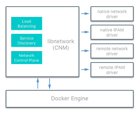
Docker Native Network Drivers
The Docker native network drivers are part of Mirantis Container Runtime and
don’t require any extra modules. They are invoked and used through standard
docker network commands. The following native network drivers exist.
| Driver | Description |
|---|---|
| Host | With the host driver, a container uses the networking stack of the
host. There is no namespace separation, and all interfaces on the host
can be used directly by the container. |
| Bridge | The bridge driver creates a Linux bridge on the host that is managed
by Docker. By default containers on a bridge can communicate with each
other. External access to containers can also be configured through the
bridge driver. |
| Overlay | The overlay driver creates an overlay network that supports
multi-host networks out of the box. It uses a combination of local Linux
bridges and VXLAN to overlay container-to-container communications over
physical network infrastructure. |
| Macvlan | The macvlan driver uses the Linux Macvlan bridge mode to establish a
connection between container interfaces and a parent host interface (or
sub-interfaces). It can be used to provide IP addresses to containers
that are routable on the physical network. Additionally VLANs can be
trunked to the macvlan driver to enforce Layer 2 container segmentation. |
| None | The none driver gives a container its own networking stack and
network namespace but does not configure interfaces inside the container.
Without additional configuration, the container is completely isolated
from the host networking stack. |
Network Scope
As seen in the docker network ls output, Docker network drivers have
a concept of scope. The network scope is the domain of the driver
which can be the local or swarm scope. Local scope drivers
provide connectivity and network services (such as DNS or IPAM) within
the scope of the host. Swarm scope drivers provide connectivity and
network services across a swarm cluster. Swarm scope networks have the
same network ID across the entire cluster while local scope networks
have a unique network ID on each host.
$ docker network ls
NETWORK ID          NAME                DRIVER              SCOPE
1475f03fbecb        bridge              bridge              local
e2d8a4bd86cb        docker_gwbridge     bridge              local
407c477060e7        host                host                local
f4zr3zrswlyg        ingress             overlay             swarm
c97909a4b198        none                null                local
Docker Remote Network Drivers
The following community- and vendor-created remote network drivers are compatible with CNM. Each provides unique capabilities and network services for containers.
| Driver | Description |
|---|---|
| contiv | An open source network plugin led by Cisco Systems to provide infrastructure and security policies for multi-tenant microservices deployments. Contiv also provides integration for non-container workloads and with physical networks, such as ACI. Contiv implements remote network and IPAM drivers. |
| weave | A network plugin that creates a virtual network that connects Docker containers across multiple hosts or clouds. Weave provides automatic discovery of applications, can operate on partially connected networks, does not require an external cluster store, and is operations friendly. |
| kuryr | A network plugin developed as part of the OpenStack Kuryr project. It implements the Docker networking (libnetwork) remote driver API by utilizing Neutron, the OpenStack networking service. Kuryr includes an IPAM driver as well. |
Docker Remote IPAM Drivers
Community and vendor created IPAM drivers can also be used to provide integrations with existing systems or special capabilities.
| Driver | Description |
|---|---|
| Infoblox | An open source IPAM plugin that provides integration with existing Infoblox tools. |
See also
There are many Docker plugins that exist and more are being created all the time. Docker maintains a list of the most common plugins.
Linux Network Fundamentals
The Linux kernel features an extremely mature and performant implementation of the TCP/IP stack (in addition to other native kernel features like VXLAN and packet filtering). Docker networking uses the kernel’s networking stack as low level primitives to create higher level network drivers. Simply put, Docker networking **is* Linux networking.*
This implementation of existing Linux kernel features ensures high performance and robustness. Most importantly, it provides portability across many distributions and versions, which enhances application portability.
There are several Linux networking building blocks which Docker uses to implement its native CNM network drivers. This list includes Linux bridges, network namespaces, veth pairs, and iptables. The combination of these tools, implemented as network drivers, provides the forwarding rules, network segmentation, and management tools for dynamic network policy.
The Linux Bridge
A Linux bridge is a Layer 2 device that is the virtual
implementation of a physical switch inside the Linux kernel. It forwards
traffic based on MAC addresses which it learns dynamically by inspecting
traffic. Linux bridges are used extensively in many of the Docker
network drivers. A Linux bridge is not to be confused with the
bridge Docker network driver which is a higher level implementation
of the Linux bridge.
Network Namespaces
A Linux network namespace is an isolated network stack in the kernel with its own interfaces, routes, and firewall rules. It is a security aspect of containers and Linux, used to isolate containers. In networking terminology they are akin to a VRF that segments the network control and data plane inside the host. Network namespaces ensure that two containers on the same host aren’t able to communicate with each other or even the host itself unless configured to do so via Docker networks. Typically, CNM network drivers implement separate namespaces for each container. However, containers can share the same network namespace or even be a part of the host’s network namespace. The host network namespace contains the host interfaces and host routing table.
Virtual Ethernet Devices
A virtual ethernet device or veth is a Linux networking
interface that acts as a connecting wire between two network namespaces.
A veth is a full duplex link that has a single interface in each
namespace. Traffic in one interface is directed out the other interface.
Docker network drivers utilize veths to provide explicit connections
between namespaces when Docker networks are created. When a container is
attached to a Docker network, one end of the veth is placed inside the
container (usually seen as the ethX interface) while the other is
attached to the Docker network.
iptables
iptables is the native packet filtering system that has been a
part of the Linux kernel since version 2.4. It’s a feature rich L3/L4
firewall that provides rule chains for packet marking, masquerading, and
dropping. The native Docker network drivers utilize iptables
extensively to segment network traffic, provide host port mapping, and
to mark traffic for load balancing decisions.
Microsoft Network Fundamentals
Networking in Windows 2016 and 2019
Docker Enterprise is supported on Windows version 2016 and above. Different network isolation mechanisms are available depending on the operating system version:
- In virtual machines (Windows 2016 only)
- Kernel based - native to the Windows operating system (default for 2019 and recommended)
In order to run Windows containers the following packages must be running:
- Windows Containers Feature
- Windows DockerMsftProvider Module
Both of these versions use similar networking features. Each container will include a virtual network adapter (vNIC) connected to a virtual switch. In the case of running Hyper-V to utilize containers this will be a Hyper-V switch. If using Microsoft native containers this will be a virtual switch created by the Host Networking Service (HNS) and attached to the primary physical nic (or vNIC in the case of virtual machines).
Windows Docker Network Drivers
Following a similar philosophy to the Linux architecture, Docker on Windows leverages operating system primitives to achieve robust policy with high throughput. Docker networking *is also Windows networking.* However, the underlying networking features differ between the two operating systems.
In addition te the overlay driver, Docker on Windows implements four
additional drivers:
- NAT (default)
- Transparent
- L2 Bridge
- L2 Tunnel
The following two tables summarize each Windows driver and the operating system features it consumes by pairing each Windows component with its functional equivalent in Linux.
| Docker Windows Network Driver | Docker Linux Network Driver |
|---|---|
| n/a | host |
| nat | bridge |
| overlay | overlay |
| l2bridge transparent | macvlan |
| none | none |
| Networking Function | Windows Primitive | Linux Primitive |
|---|---|---|
| Layer 2 connectivity | Hyper-V vmSwitch | bridge interface |
| Endpoint | Host Network Service vNic | veth interface |
| Policy | Virtual Filtering Platform | iptables |
| VXLAN Virtual Network Encapsulation | Virtual Filtering Platform | vxlan interface |
Transparent Driver
The Transparent network driver in Windows container environments allows one to connect containers directly to the physical network. Containers will be able to pick up an IP address from an external DHCP server, or you can assign IP addresses statically.
L2 Bridge / L2 Tunnel Driver
L2 Bridge / L2Tunnel is a network driver associated with public and private cloud deployments. This network driver does layer-2 address translation that allows your containers to have the same subnet as the host machine. Each container under the L2 bridge network will have a unique IP address but will share the same MAC address as the container host. Only static IP assignment is supported for this type of network mode.
Joining Windows to the Swarm
When joining a Windows worker to the swarm for the first time, Windows
will use HNS to apply a vNIC and NAT network to the Windows OS. The
nat network is the default network for containers running on
Windows. Any containers started on Windows without a specific network
configuration will be attached to the default nat network, and
automatically assigned an IP address from the nat network’s internal
prefix IP range: 172.x.x.x/16.
See also
For further details on Windows networking architecture and design, see Windows Container Networking Overview
Docker Network Control Plane
The Docker-distributed network control plane manages the state of Swarm-scoped Docker networks in addition to propagating control plane data. It is a built-in capability of Docker Swarm clusters and does not require any extra components such as an external KV store. The control plane uses a Gossip protocol based on SWIM to propagate network state information across Docker container clusters (think a network to read and maintain a lot of chatter between a lot of nodes). The Gossip protocol is highly efficient at reaching eventual consistency within the cluster while maintaining constant message rates, failure detection times, and convergence time across very large scale clusters. This ensures that the network is able to scale across many nodes without introducing scaling issues such as slow convergence or false positive node failures.
The control plane is highly secure, providing confidentiality, integrity, and authentication through encrypted channels. It is also scoped per network which greatly reduces the updates that any given host receives.
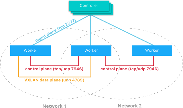
The network control plane is composed of several components that work together to achieve fast convergence across large scale networks. The distributed nature of the control plane ensures that cluster controller failures don’t affect network performance.
The Docker network control plane components are as follows:
- Message Dissemination updates nodes in a peer-to-peer fashion fanning out the information in each exchange to a larger group of nodes. Fixed intervals and peer group size ensures that network usage is constant even as the size of the cluster scales. Exponential information propagation across peers ensures that convergence is fast and bounded across any cluster size.
- Failure Detection utilizes direct and indirect hello messages to rule out network congestion and specific paths from causing false positive node failures.
- Full State Syncs occur periodically to achieve consistency faster and resolve temporary network partitions.
- Topology Aware algorithms understand the relative latency between themselves and other peers. This is used to optimize the peer groups which makes convergence faster and more efficient.
- Control Plane Encryption protects against man-in-the-middle and other attacks that could compromise network security.
Note
The Docker Network Control Plane is a component of Swarm and requires a Swarm mode cluster to operate.
Docker Host Network Driver
The host network driver is most familiar to those new to Docker
because it’s the same networking configuration that Linux uses without
Docker. --net=host effectively turns Docker networking off and
containers use the host (or default) networking stack of the host
operating system.
Typically with other networking drivers, each container is placed in its
own network namespace (or sandbox) to provide complete network
isolation from each other. With the host driver containers are all
in the same host network namespace and use the network interfaces and IP
stack of the host. All containers in the host network are able to
communicate with each other on the host interfaces. From a networking
standpoint this is equivalent to multiple processes running on a host
without containers. Because they are using the same host interfaces, no
two containers are able to bind to the same TCP port. This may cause
port contention if multiple containers are being scheduled on the same
host.
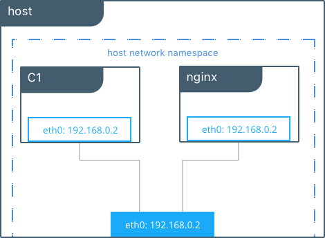
# Create containers attached to the host network interface
host $ docker run --rm -itd --net host --name C1 alpine sh

host $ docker run --rm -itd --net host --name nginx nginx

# Show eth0 on the host
host $ ip -o -4 address show dev eth0 |cut -d’ ‘ -f1-7
2: eth0    inet 172.31.21.213/20

# Start a shell in the container C1 and show eth0 from C1
host $ docker exec -it C1 sh

C1 $ ip -o -4 address show dev eth0 | cut -d' ' -f1-7
2: eth0    inet 172.31.21.213/20

# Contact the nginx container through localhost on C1
C1 $ curl localhost
!DOCTYPE html>
<html>
<head>
<title>Welcome to nginx!</title>
...
In this example, the host (host), the container (C1), and nginx all
share the same interface for eth0 when containers use the host network.
This makes host ill-suited for multi-tenant or highly secure
applications. host containers have network access to every other
container on the host. Communication is possible between containers
using localhost as shown in the example when curl localhost is
executed from C1.
With the host driver, Docker does not manage any portion of the
container networking stack such as port mapping or routing rules. This
means that common networking flags like -p and --icc have no
meaning for the host driver. They are ignored. This does make the
host networking the simplest and lowest latency of the networking
drivers. The traffic path goes directly from the container process to
the host interface, offering bare-metal performance that is equivalent
to a non-containerized process.
Full host access and no automated policy management may make the
host driver a difficult fit as a general network driver. However,
host does have some interesting properties that may be applicable
for use cases such as ultra high performance applications or application
troubleshooting.
The host networking driver only works on Linux hosts, and is not supported on Docker Desktop, Docker Desktop Enterprise, or Mirantis Container Runtime on Windows Server.
Docker Bridge Network Driver
This section explains the default Docker bridge network as well as user-defined bridge networks.
Default Docker Bridge Network
On any Linux host running Mirantis Container Runtime, there is, by default, a
local Docker network named bridge. This network is created using a
bridge network driver which instantiates a Linux bridge called docker0.
This may sound confusing.
bridgeis the name of the Docker networkbridgeis the Docker network driver, or template, from which this network is createddocker0is the name of the Linux bridge that is the kernel building block used to implement this network
On a standalone Linux Docker host, bridge is the default network that
containers connect to if no other network is specified(the analog on Windows is
the nat network type). In the following example a container is created with no
network parameters. Mirantis Container Runtime connects it to the bridge
network by default. Inside the container, notice eth0 which is created by
the bridge driver and given an address by the Docker native IPAM driver.
# Create a busybox container named "C1" and show its IP addresses
host $ docker run --rm -it --name C1 busybox sh
C1 $ ip address
4: eth0@if5: <BROADCAST,MULTICAST,UP,LOWER_UP,M-DOWN> mtu 1500 qdisc noqueue
    link/ether 02:42:ac:11:00:02 brd ff:ff:ff:ff:ff:ff
    inet 172.17.0.2/16 scope global eth0
...
Note
A container interface’s MAC address is dynamically generated and
embeds the IP address to avoid collision. Here ac:11:00:02
corresponds to 172.17.0.2.
The tool brctl on the host shows the Linux bridges that exist in the
host network namespace. It shows a single bridge called docker0.
docker0 has one interface, vetha3788c4, which provides
connectivity from the bridge to the eth0 interface inside container
C1.
host $ brctl show
bridge name      bridge id            STP enabled    interfaces
docker0          8000.0242504b5200    no             vethb64e8b8
Inside container C1, the container routing table directs traffic to
eth0 of the container and thus the docker0 bridge.
C1 $ ip route
default via 172.17.0.1 dev eth0
172.17.0.0/16 dev eth0  src 172.17.0.2
A container can have zero to many interfaces depending on how many networks it is connected to. Each Docker network can only have a single interface per container.
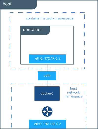
As shown in the host routing table, the IP interfaces in the global
network namespace now include docker0. The host routing table
provides connectivity between docker0 and eth0 on the external
network, completing the path from inside the container to the external
network.
host $ ip route
default via 172.31.16.1 dev eth0
172.17.0.0/16 dev docker0  proto kernel  scope link  src 172.17.42.1
172.31.16.0/20 dev eth0  proto kernel  scope link  src 172.31.16.102
By default bridge is assigned one subnet from the ranges
172.[17-31].0.0/16 or 192.168.[0-256].0/20 which does not overlap with
any existing host interface. The default bridge network can also be
configured to use user-supplied address
ranges.
Also, an existing Linux bridge can be used for the bridge network
rather than Docker creating one. Go to the Mirantis Container Runtime
docs
for more information about customizing bridge.
Note
The default bridge network is the only network that supports
legacy
links.
Name-based service discovery and user-provided IP addresses are
not supported by the default bridge network.
User-Defined Bridge Networks
In addition to the default networks, users can create their own networks
called user-defined networks of any network driver type. In the case
of user-defined bridge networks, a new Linux bridge is setup on the
host. Unlike the default bridge network, user-defined networks
supports manual IP address and subnet assignment. If an assignment isn’t
given, then Docker’s default IPAM driver assigns the next subnet
available in the private IP space.
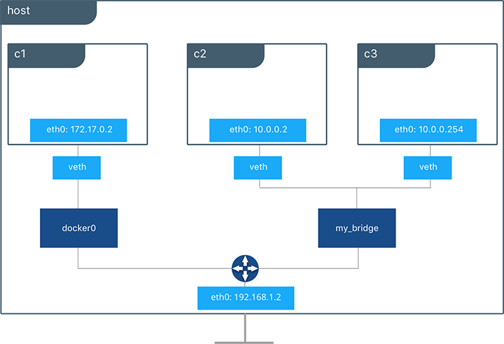
Below a user-defined bridge network is created with two containers
attached to it. A subnet is specified, and the network is named
my_bridge. One container is not given IP parameters, so the IPAM
driver assigns it the next available IP in the subnet. The other
container has its IP specified.
$ docker network create -d bridge --subnet 10.0.0.0/24 my_bridge
$ docker run --rm -itd --name C2 --net my_bridge busybox sh
$ docker run --rm -itd --name C3 --net my_bridge --ip 10.0.0.254 busybox sh
brctl now shows a second Linux bridge on the host. The name of the
Linux bridge, br-4bcC22f5e5b9, matches the Network ID of the
my_bridge network. my_bridge also has two veth interfaces
connected to containers C2 and C3.
$ brctl show
bridge name      bridge id            STP enabled    interfaces
br-b5db4578d8c9  8000.02428d936bb1    no             vethc9b3282
                                                     vethf3ba8b5
docker0          8000.0242504b5200    no             vethb64e8b8

$ docker network ls
NETWORK ID          NAME                DRIVER              SCOPE
b5db4578d8c9        my_bridge           bridge              local
e1cac9da3116        bridge              bridge              local
...
Listing the global network namespace interfaces shows the Linux networking
circuitry that’s been instantiated by Mirantis Container Runtime. Each veth
and Linux bridge interface appears as a link between one of the Linux bridges
and the container network namespaces.
$ ip link

1: lo: <LOOPBACK,UP,LOWER_UP> mtu 65536
2: eth0: <BROADCAST,MULTICAST,UP,LOWER_UP> mtu 9001
3: docker0: <BROADCAST,MULTICAST,UP,LOWER_UP> mtu 1500
5: vethb64e8b8@if4: <BROADCAST,MULTICAST,UP,LOWER_UP> mtu 1500
6: br-b5db4578d8c9: <BROADCAST,MULTICAST,UP,LOWER_UP> mtu 1500
8: vethc9b3282@if7: <BROADCAST,MULTICAST,UP,LOWER_UP> mtu 1500
10: vethf3ba8b5@if9: <BROADCAST,MULTICAST,UP,LOWER_UP> mtu 1500
...
External Access for Standalone Containers
By default all containers on the same Docker network (multi-host swarm scope or local scope) have connectivity with each other on all ports. Communication between different Docker networks and container ingress traffic that originates from outside Docker is firewalled. This is a fundamental security aspect that protects container applications from the outside world and from each other. This is outlined in more detail in security.
For most types of Docker networks (bridge and overlay included)
external ingress access for applications must be explicitly granted.
This is done through internal port mapping. Docker publishes ports
exposed on host interfaces to internal container interfaces. The
following diagram depicts ingress (bottom arrow) and egress (top arrow)
traffic to container C2. Outbound (egress) container traffic is
allowed by default. Egress connections initiated by containers are
masqueraded/SNATed to an ephemeral port (typically in the range of
32768 to 60999). Return traffic on this connection is allowed, and thus
the container uses the best routable IP address of the host on the
ephemeral port.
Ingress access is provided through explicit port publishing. Port publishing is done by Mirantis Container Runtime and can be controlled through MKE or the Mirantis Container Runtime CLI. A specific or randomly chosen port can be configured to expose a service or container. The port can be set to listen on a specific (or all) host interfaces, and all traffic is mapped from this port to a port and interface inside the container.
$ docker run -d --name C2 --net my_bridge -p 5000:80 nginx
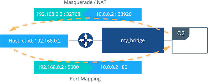
External access is configured using --publish / -p in the Docker
CLI or MKE. After running the above command, the diagram shows that
container C2 is connected to the my_bridge network and has an IP
address of 10.0.0.2. The container exposes its service to the
outside world on port 5000 of the host interface 192.168.0.2.
All traffic going to this interface:port is port published to
10.0.0.2:80 of the container interface.
Outbound traffic initiated by the container is masqueraded so that it is
sourced from ephemeral port 32768 on the host interface
192.168.0.2. Return traffic uses the same IP address and port for
its destination and is masqueraded internally back to the container
address:port 10.0.0.2:33920. When using port publishing, external
traffic on the network always uses the host IP and exposed port and
never the container IP and internal port.
For information about exposing containers and services in a cluster of Mirantis Container Runtimes read External Access for Swarm Services.
Overlay Driver Network Architecture
The native Docker overlay network driver radically simplifies many
of the challenges in multi-host networking. With the overlay driver,
multi-host networks are first-class citizens inside Docker without
external provisioning or components. overlay uses the
Swarm-distributed control plane to provide centralized management,
stability, and security across very large scale clusters. Overlay
networks function across Linux and Windows hosts.
VXLAN Data Plane
The overlay driver utilizes an industry-standard VXLAN data plane
that decouples the container network from the underlying physical
network (the underlay). The Docker overlay network encapsulates
container traffic in a VXLAN header which allows the traffic to traverse
the physical Layer 2 or Layer 3 network. The overlay makes network
segmentation dynamic and easy to control no matter what the underlying
physical topology. Use of the standard IETF VXLAN header promotes
standard tooling to inspect and analyze network traffic.
VXLAN has been a part of the Linux kernel since version 3.7, and Docker uses the native VXLAN features of the kernel to create overlay networks. The Docker overlay datapath is entirely in kernel space. This results in fewer context switches, less CPU overhead, and a low-latency, direct traffic path between applications and the physical NIC.
IETF VXLAN (RFC 7348) is a data-layer encapsulation format that overlays Layer 2 segments over Layer 3 networks. VXLAN is designed to be used in standard IP networks and can support large-scale, multi-tenant designs on shared physical network infrastructure. Existing on-premises and cloud-based networks can support VXLAN transparently.
VXLAN is defined as a MAC-in-UDP encapsulation that places container Layer 2 frames inside an underlay IP/UDP header. The underlay IP/UDP header provides the transport between hosts on the underlay network. The overlay is the stateless VXLAN tunnel that exists as point-to-multipoint connections between each host participating in a given overlay network. Because the overlay is independent of the underlay topology, applications become more portable. Thus, network policy and connectivity can be transported with the application whether it is on-premises, on a developer desktop, or in a public cloud.
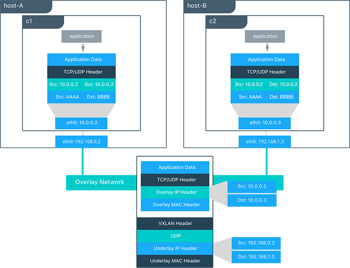
In this diagram, the packet flow on an overlay network is shown. Here
are the steps that take place when C1 sends C2 packets across
their shared overlay network:
C1does a DNS lookup forC2. Since both containers are on the same overlay network the Mirantis Container Runtime local DNS server resolvesC2to its overlay IP address10.0.0.3.- An overlay network is a L2 segment so
C1generates an L2 frame destined for the MAC address ofC2. - If this is the first time C1 has contacted C2, C1 issues an ARP request for C2, which is answered by the local operating system using an entry statically programmed by the local Mirantis Container Runtime.
- The frame is encapsulated with a VXLAN header by the
overlaynetwork driver. The distributed overlay control plane manages the locations and state of each VXLAN tunnel endpoint so it knows thatC2resides onhost-Bat the physical address of192.168.0.3. That address becomes the destination address of the underlay IP header. - Once encapsulated the packet is sent. The physical network is responsible of routing or bridging the VXLAN packet to the correct host.
- The packet arrives at the
eth0interface ofhost-Band is decapsulated by theoverlaynetwork driver. The original L2 frame fromC1is passed toC2’seth0interface and up to the listening application.
Overlay Driver Internal Architecture
The Docker Swarm control plane automates all of the provisioning for an
overlay network. No VXLAN configuration or operating system networking
configuration is required. Data-plane encryption, an optional feature of
overlays on Linux, is also automatically configured by the overlay
driver as networks are created. The user or network operator only has to
define the network (docker network create -d overlay ...) and attach
containers to that network.
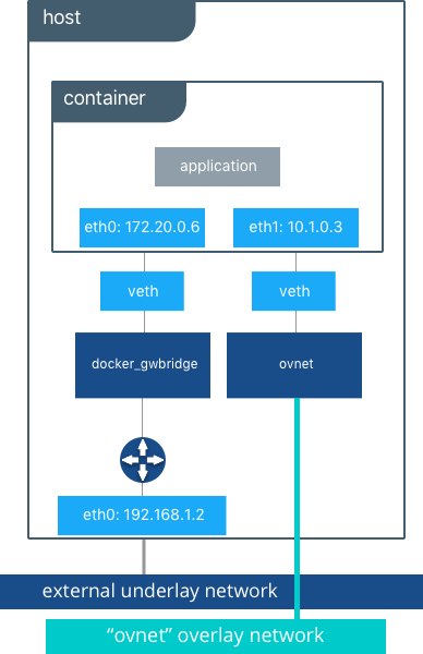
During overlay network creation, Mirantis Container Runtime creates the network infrastructure required for overlays on each host. A Linux bridge is created per overlay along with its associated VXLAN interfaces. The Mirantis Container Runtime intelligently instantiates overlay networks on hosts only when a container attached to that network is scheduled on the host. This prevents sprawl of overlay networks where connected containers do not exist.
The following example creates an overlay network and attaches a container to that network. The Docker Swarm/MKE automatically creates the overlay network. The following example requires Swarm or MKE to be set up beforehand.
# Create an overlay named "ovnet" with the overlay driver
$ docker network create -d overlay --subnet 10.1.0.0/24 ovnet

# Create a service from running nginx and connect it to the "ovnet" network
$ docker service create --network ovnet nginx
When the overlay network is created, notice that several interfaces and bridges are created inside the host as well as two interfaces inside this container.
# Peek into the container of this service to see its internal interfaces
$ ip address

# docker_gwbridge network
52: eth0@if55: <BROADCAST,MULTICAST,UP,LOWER_UP> mtu 1500
    link/ether 02:42:ac:14:00:06 brd ff:ff:ff:ff:ff:ff
    inet 172.20.0.6/16 scope global eth1
       valid_lft forever preferred_lft forever
    inet6 fe80::42:acff:fe14:6/64 scope link
       valid_lft forever preferred_lft forever

# overlay network interface
54: eth1@if53: <BROADCAST,MULTICAST,UP,LOWER_UP> mtu 1450
    link/ether 02:42:0a:01:00:03 brd ff:ff:ff:ff:ff:ff
    inet 10.1.0.3/24 scope global eth0
       valid_lft forever preferred_lft forever
    inet 10.1.0.2/32 scope global eth0
       valid_lft forever preferred_lft forever
    inet6 fe80::42:aff:fe01:3/64 scope link
       valid_lft forever preferred_lft forever
Two interfaces have been created inside the container that correspond to
two bridges that now exist on the host. On overlay networks, each
container has at least two interfaces that connect it to the overlay
and the docker_gwbridge respectively.
| Bridge | Purpose |
|---|---|
| overlay | The connection point to the overlay network that VXLAN encapsulates and (optionally) encrypts traffic between containers on the same overlay network. It extends the overlay across all hosts participating in this particular overlay. One existed per overlay subnet on a host, and it has the same name that a particular overlay network is given. |
| docker_gwbridge | The egress bridge for traffic leaving the cluster. Only one
docker_gwbridge exists per host. Container-to-Container traffic is
blocked on this bridge allowing only ingress/egress traffic. |
External Access for Docker Services
Swarm & MKE provide access to services from outside the cluster port
publishing. Ingress and egress for services do not depend on centralized
gateways, but distributed ingres/egress on the host where the specific
service task is running. There are two modes of port publishing for
services, host mode and ingress mode.
Ingress Mode Service Publishing
ingress mode port publishing utilizes the Swarm Routing
Mesh
to apply load balancing across the tasks in a service. Ingress mode
publishes the exposed port on every MKE/Swarm node. Ingress traffic to
the published port is load balanced by the Routing Mesh and directed via
round robin load balancing to one of the healthy tasks of the service.
Even if a given host is not running a service task, the port is
published on the host and is load balanced to a host that has a task.
When Swarm signals a task to stop, its loadbalancer entry is quiesced so
that it stops receiving new traffic.
$ docker service create --replicas 2 --publish mode=ingress,target=80,published=8080 nginx
Note
mode=ingress is the default mode for services. This command can
also be written with the shorthand version -p 80:8080. Port
8080 is exposed on every host on the cluster and load balanced
to the two containers in this service.
Host Mode Service Publishing
host mode port publishing exposes ports only on the host where
specific service tasks are running. The port is mapped directly to the
container on that host. To prevent port collision only a single task of
a given service can run on each host.
$ docker service create --replicas 2 --publish mode=host,target=80,published=8080 nginx
Note
host mode requires the mode=host flag. It publishes port
8080 locally on the hosts where these two containers are
running. It does not apply load balancing, so traffic to those nodes
are directed only to the local container. This can cause port
collision if there are not enough hosts with the published port
available for the number of replicas.
Ingress Design
There are many good use-cases for either publishing mode. ingress
mode works well for services that have multiple replicas and require
load balancing between those replicas. host mode works well if
external service discovery is already provided by another tool. Another
good use case for host mode is for global containers that exist one
per host. These containers may expose specific information about the
local host (such as monitoring or logging) that are only relevant for
that host and so you would not want to load balance when accessing that
service.
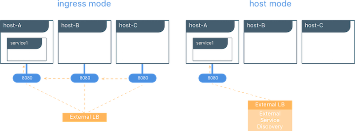
MACVLAN
The macvlan driver is a new implementation of the tried and true
network virtualization technique. The Linux implementations are
extremely lightweight because rather than using a Linux bridge for
isolation, they are simply associated with a Linux Ethernet interface or
sub-interface to enforce separation between networks and connectivity to
the physical network.
MACVLAN offers a number of unique features and capabilities. It has positive performance implications by virtue of having a very simple and lightweight architecture. Rather than port mapping, the MACVLAN driver provides direct access between containers and the physical network. It also allows containers to receive routable IP addresses that are on the subnet of the physical network.
MACVLAN use-cases may include:
- Very low-latency applications
- Network design that requires containers be on the same subnet as and using IPs as the external host network
The macvlan driver uses the concept of a parent interface. This
interface can be a physical interface such as eth0, a sub-interface
for 802.1q VLAN tagging like eth0.10 (.10 representing
VLAN 10), or even a bonded host adaptor which bundles two Ethernet
interfaces into a single logical interface.
A gateway address is required during MACVLAN network configuration. The gateway must be external to the host provided by the network infrastructure. MACVLAN networks allow access between containers on the same network. Access between different MACVLAN networks on the same host is not possible without routing outside the host.
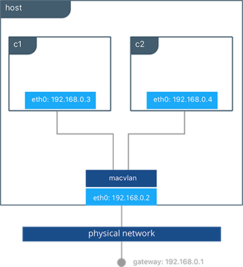
This example binds a MACVLAN network to eth0 on the host. It also
attaches two containers to the MACVLAN network and shows that they can
ping between themselves. Each container has an address on the
192.168.0.0/24 physical network subnet and its default gateway is an
interface in the physical network.
# Create of MACVLAN network "mvnet" bound to eth0 on the host
$ docker network create -d macvlan --subnet 192.168.0.0/24 --gateway 192.168.0.1 -o parent=eth0 mvnet

# Create two containers on the "mvnet" network
$ docker run --rm -itd --name C1 --net mvnet --ip 192.168.0.3 busybox sh
$ docker run --rm -it --name C2 --net mvnet --ip 192.168.0.4 busybox sh

$ ping 192.168.0.3
PING 127.0.0.1 (127.0.0.1): 56 data bytes
64 bytes from 127.0.0.1: icmp_seq=0 ttl=64 time=0.052 ms
As you can see in this diagram, C1 and C2 are attached via the
MACVLAN network called mvnet attached to eth0 on the host.
VLAN Trunking with MACVLAN
Trunking 802.1q to a Linux host is notoriously painful for many in
operations. It requires configuration file changes in order to be
persistent through a reboot. If a bridge is involved, a physical NIC
needs to be moved into the bridge, and the bridge then gets the IP
address. The macvlan driver completely manages sub-interfaces and
other components of the MACVLAN network through creation, destruction,
and host reboots.
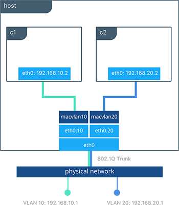
When the macvlan driver is instantiated with sub-interfaces it
allows VLAN trunking to the host and segments containers at L2. The
macvlan driver automatically creates the sub-interfaces and connects
them to the container interfaces. As a result each container is in a
different VLAN, and communication is not possible between them unless
traffic is routed in the physical network.
# Create a network called “macvlan10” in VLAN 10
$ docker network create -d macvlan --subnet 192.168.10.0/24 --gateway 192.168.10.1 \
    -o parent=eth0.10 macvlan10

# Create a network called "macvlan20" network in VLAN 20
$ docker network create -d macvlan --subnet 192.168.20.0/24 --gateway 192.168.20.1 \
    -o parent=eth0.20 macvlan20

# Create two containers on separate MACVLAN networks
$ docker run --rm -itd --name C1 --net macvlan10 --ip 192.168.10.2 busybox sh
$ docker run --rm -it --name C2 --net macvlan20 --ip 192.168.20.2 busybox sh
In the preceding configuration we’ve created two separate networks using
the macvlan driver that are configured to use a sub-interface as
their parent interface. The macvlan driver creates the
sub-interfaces and connects them between the host’s eth0 and the
container interfaces. The host interface and upstream switch must be set
to switchport mode trunk so that VLANs are tagged going across the
interface. One or more containers can be connected to a given MACVLAN
network to create complex network policies that are segmented via L2.
Because multiple MAC addresses are living behind a single host interface you might need to enable promiscuous mode on the interface depending on the NIC’s support for MAC filtering.
None (Isolated) Network Driver
Similar to the host network driver, the none network driver is
essentially an unmanaged networking option. Mirantis Container Runtime does not
create interfaces inside the container, establish port mapping, or
install routes for connectivity. A container using --net=none is
completely isolated from other containers and the host. If network
connectivity is required, the networking admin or external tools must be
used to provide this plumbing. A container using none only has a
loopback interface and no other interfaces.
Unlike the host driver, the none driver creates a separate
namespace for each container. This guarantees container network
isolation between any containers and the host.
Note
Containers using --net=none or --net=host cannot be
connected to any other Docker networks.
Physical Network Design Requirements
Docker Enterprise and Docker networking are designed to run over common data center network infrastructure and topologies. Its centralized controller and fault-tolerant cluster guarantee compatibility across a wide range of network environments. The components that provide networking functionality (network provisioning, MAC learning, overlay encryption) are either a part of MKE, Mirantis Container Runtime, or the host operating system itself. No extra components or special networking features are required to run any of the native Docker networking drivers.
More specifically, the Docker native network drivers have NO requirements for:
- Multicast
- External key-value stores
- Specific routing protocols
- Layer 2 adjacencies between hosts
- Specific topologies such as spine & leaf, traditional 3-tier, and PoD designs. Any of these topologies are supported.
This is in line with the Container Networking Model which promotes application portability across all environments while still achieving the performance and policy required of applications.
Swarm Native Service Discovery
Docker uses embedded DNS to provide service discovery for containers running on
a single Mirantis Container Runtime and tasks running in a Docker Swarm.
Mirantis Container Runtime has an internal DNS server that provides name
resolution to all of the containers on the host in user-defined bridge,
overlay, and MACVLAN networks. Each Docker container ( or task in Swarm
mode) has a DNS resolver that forwards DNS queries to Mirantis Container
Runtime, which acts as a DNS server. Mirantis Container Runtime then checks if
the DNS query belongs to a container or service on network(s) that the
requesting container belongs to. If it does, then Mirantis Container Runtime
looks up the IP address that matches a container, task, orservice’s
name in its key-value store and returns that IP or service Virtual IP
(VIP) back to the requester.
Service discovery is network-scoped, meaning only containers or tasks that are on the same network can use the embedded DNS functionality. Containers not on the same network cannot resolve each other’s addresses. Additionally, only the nodes that have containers or tasks on a particular network store that network’s DNS entries. This promotes security and performance.
If the destination container or service does not belong on the same
network(s) as the source container, then Mirantis Container Runtime forwards
the DNS query to the configured default DNS server.
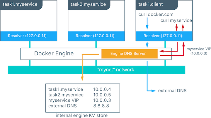
In this example there is a service of two containers called
myservice. A second service (client) exists on the same network.
The client executes two curl operations for docker.com and
myservice. These are the resulting actions:
- DNS queries are initiated by
clientfordocker.comandmyservice. - The container’s built-in resolver intercepts the DNS queries on
127.0.0.11:53and sends them to Mirantis Container Runtime’s DNS server. myserviceresolves to the Virtual IP (VIP) of that service which is load balanced by the operating system network stack to the individual task IP addresses. Container names resolve as well, albeit directly to their IP addresses.docker.comdoes not exist as a service name in themynetnetwork and so the request is forwarded to the configured default DNS server.
Docker Native Load Balancing
Docker Swarm clusters have built-in internal and external load balancing capabilities are built right in to the engine that leverage the operating system networking stack. Internal load balancing provides for load balancing between containers within the same Swarm or MKE cluster. External load balancing provides for the load balancing of ingress traffic entering a cluster.
MKE Internal Load Balancing
Internal load balancing is instantiated automatically when Docker services are created. When services are created in a Docker Swarm cluster, they are automatically assigned a Virtual IP (VIP) that is part of the service’s network. The VIP is returned when resolving the service’s name. Traffic to that VIP is automatically sent to all healthy tasks of that service across the overlay network. This approach avoids any application-level load balancing because only a single IP is returned to the client. Docker takes care of routing and equally distributing the traffic across the healthy service tasks.

To see the VIP, run a docker service inspect my_service as follows:
# Create an overlay network called mynet
$ docker network create -d overlay mynet
a59umzkdj2r0ua7x8jxd84dhr

# Create myservice with 2 replicas as part of that network
$ docker service create --network mynet --name myservice --replicas 2 busybox ping localhost
8t5r8cr0f0h6k2C3k7ih4l6f5

# See the VIP that was created for that service
$ docker service inspect myservice
...

"VirtualIPs": [
                {
                    "NetworkID": "a59umzkdj2r0ua7x8jxd84dhr",
                    "Addr": "10.0.0.3/24"
                },
]
Note
DNS round robin (DNS RR) load balancing is another load balancing
option for services (configured with --endpoint-mode dnsrr). In
DNS RR mode a VIP is not created for each service. The Docker DNS
server resolves a service name to individual container IPs in round
robin fashion.
Swarm External L4 Load Balancing (Docker Routing Mesh)
You can expose services externally by using the --publish flag when
creating or updating the service. Publishing ports in Docker Swarm mode
means that every node in your cluster is listening on that port. But
what happens if the service’s task isn’t on the node that is listening
on that port?
This is where routing mesh comes into play. Routing mesh leverages
operating system primitives (IPVS+iptables on Linux and VFP on Windows)
to create a powerful cluster-wide transport-layer (L4) load balancer. It
allows the Swarm nodes to accept connections on the services’ published
ports. When any Swarm node receives traffic destined to the published
TCP/UDP port of a running service, it forwards it to service’s VIP
using a pre-defined overlay network called ingress. The ingress
network behaves similarly to other overlay networks but its sole purpose
is to provide inter-host transport for mesh routing traffic from
external clients to cluster services. It uses the same VIP-based
internal load balancing as described in the previous section.
Once you launch services, you can create an external DNS record for your applications and map it to any or all Docker Swarm nodes. You do not need to know where the container is running as all nodes in your cluster look as one with the routing mesh routing feature.
# Create a service with two replicas and publish port 8000 on the cluster
$ docker service create --name app --replicas 2 --network appnet -p 8000:80 nginx
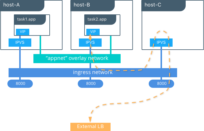
This diagram illustrates how the routing mesh works.
- A service is created with two replicas, and it is port mapped
externally to port
8000. - The routing mesh exposes port
8000on each host in the cluster. - Traffic destined for the
appcan enter on any host. In this case the external LB sends the traffic to a host without a service replica. - The kernel’s IPVS load balancer redirects traffic on the
ingressoverlay network to a healthy service replica.
MKE External L7 Load Balancing (HTTP Routing Mesh)
MKE provides built-in L7 HTTP/HTTPS load balancing. URLs can be load balanced to services and load balanced across the service replicas.

See also
Check out the ucp-ingress-swarm reference architecture to learn more about the MKE layer 7 load balanceing design.
Docker Network Security and Encryption
Network security is a top-of-mind consideration when designing and implementing containerized workloads with Docker. In this section, key security considerations when deploying Docker networks are covered.
Network Segmentation and Data Plane Security
Docker manages distributed firewall rules to segment Docker networks and prevent malicious access to container resources. By default, Docker networks are segmented from each other to prevent traffic between them. This approach provides true network isolation at Layer 3.
The Docker engine manages host firewall rules that prevent access between networks and manages ports for exposed containers. In a Swarm & MKE clusters this creates a distributed firewall that dynamically protects applications as they are scheduled in the cluster.
This table outlines some of the access policies with Docker networks.
| Path | Access |
|---|---|
| Within a Docker Network | Access is permitted between all containers on all ports on the same Docker network. This applies for all network types - swarm scope, local scope, built-in, and remote drivers. |
| Between Docker Networks | Access is denied between Docker networks by distributed host firewall rules that are managed by the Docker engine. Containers can be attached to multiple networks to communicate between different Docker networks. Network connectivity between Docker networks can also be managed external to the host via API. |
| Egress from a Docker Network | Traffic originating from inside a Docker network destined for outside a Docker host is permitted. The host’s local, stateful firewall tracks connections to permit responses for that connection. |
| Ingress to a Docker Network | Ingress traffic is denied by default. Port exposure through host ports or ingress mode ports provides explicit ingress access. An exception to this is the MACVLAN driver which operates in the same IP space as the external network and is fully open within that network. Other remote drivers that operate similarly to MACVLAN may also allow ingress traffic. |
Control Plane Security
Docker Swarm comes with integrated PKI. All managers and nodes in the Swarm have a cryptographically signed identity in the form of a signed certificate. All manager-to-manager and manager-to-node control communication is secured out of the box with TLS. There is no need to generate certs externally or set up any CAs manually to get end-to-end control plane traffic secured in Docker Swarm mode. Certificates are periodically and automatically rotated.
Data Plane Network Encryption
Docker supports IPSec encryption for overlay networks between Linux hosts out-of-the-box. The Swarm & MKE managed IPSec tunnels encrypt network traffic as it leaves the source container and decrypts it as it enters the destination container. This ensures that your application traffic is highly secure when it’s in transit regardless of the underlying networks. In a hybrid, multi-tenant, or multi-cloud environment, it is crucial to ensure data is secure as it traverses networks you might not have control over.
This diagram illustrates how to secure communication between two containers running on different hosts in a Docker Swarm.
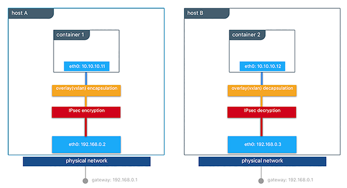
This feature works can be enabled per network at the time of creation by
adding the --opt encrypted=true option (e.g
docker network create -d overlay --opt encrypted=true <NETWORK_NAME>).
After the network gets created, you can launch services on that network
(e.g
docker service create --network <NETWORK_NAME> <IMAGE> <COMMAND>).
When two tasks of the same network are created on two different hosts,
an IPsec tunnel is created between them and traffic gets encrypted as it
leaves the source host and decrypted as it enters the destination host.
The Swarm leader periodically regenerates a symmetrical key and distributes it securely to all cluster nodes. This key is used by IPsec to encrypt and decrypt data plane traffic. The encryption is implemented via IPSec in host-to-host transport mode using AES-GCM.
Management Plane Security & RBAC with MKE
When creating networks with MKE, teams and labels define access to container resources. Resource permission labels define who can view, configure, and use certain Docker networks.

This MKE screenshot shows the use of the label production-team to
control access to this network to only members of that team.
Additionally, options like network encryption and others can be toggled
via MKE.
IP Address Management
The Container Networking Model (CNM) provides flexibility in how IP addresses are managed. There are two methods for IP address management.
- CNM has a native IPAM driver that does simple allocation of IP addresses globally for a cluster and prevents overlapping allocations. The native IPAM driver is what is used by default if no other driver is specified.
- CNM has interfaces to use remote IPAM drivers from other vendors and the community. These drivers can provide integration into existing vendor or self-built IPAM tools.
Manual configuration of container IP addresses and network subnets can be done using MKE, the CLI, or Docker APIs. The address request goes through the chosen driver which then decides how to process the request.
Subnet size and design is largely dependent on a given application and the specific network driver. IP address space design is covered in more depth for each Network Deployment Model in the next section. The uses of port mapping, overlays, and MACVLAN all have implications on how IP addressing is arranged. In general, container addressing falls into two buckets. Internal container networks (bridge and overlay) address containers with IP addresses that are not routable on the physical network by default. You can find more information about customizing the behavior of the Internal IPAM in the MKE Installation Documentation. MACVLAN networks provide IP addresses to containers that are on the subnet of the physical network. Thus, traffic from container interfaces can be routable on the physical network. It is important to note that subnets for internal networks (bridge, overlay) should not conflict with the IP space of the physical underlay network. Overlapping address space can cause traffic to not reach its destination.
Network Troubleshooting
Docker network troubleshooting can be difficult for devops and network
engineers. With proper understanding of how Docker networking works and
the right set of tools, you can troubleshoot and resolve these network
issues. One recommended way is to use the
netshoot container to
troubleshoot network problems. The netshoot container has a set of
powerful networking troubleshooting tools that can be used to
troubleshoot Docker network issues.
The power of using a troubleshooting container like netshoot is that the
network troubleshooting tools are portable. The netshoot container
can be attached to any network, can be placed in the host network
namespace, or in another container’s network namespace to inspect any
viewpoint of the host network.
It containers the following tools and more:
- iperf
- tcpdump
- netstat
- iftop
- drill
- util-linux (nsenter)
- curl
- nmap
Network Deployment Models
The following example uses a fictional app called `Docker Pets <https://github.com/mark-church/docker-pets>`__ to illustrate the Network Deployment Models. It serves up images of pets on a web page while counting the number of hits to the page in a backend database.
webis a front-end web server based on thechrch/docker-pets:1.0imagedbis aconsulbackend
chrch/docker-pets expects an environment variable DB that tells
it how to find the backend db service.
Bridge Driver on a Single Host
This model is the default behavior of the native Docker bridge
network driver. The bridge driver creates a private network internal
to the host and provides an external port mapping on a host interface
for external connectivity.
$ docker network create -d bridge petsBridge

$ docker run -d --net petsBridge --name db consul

$ docker run -it --env "DB=db" --net petsBridge --name web -p 8000:5000 chrch/docker-pets:1.0
Starting web container e750c649a6b5
 * Running on http://0.0.0.0:5000/ (Press CTRL+C to quit)
Note
When an IP address is not specified, port mapping is exposed on all
interfaces of a host. In this case the container’s application is
exposed on 0.0.0.0:8000. To provide a specific IP address to
advertise on use the flag -p IP:host_port:container_port. More
options to expose ports can be found in the Docker
docs.
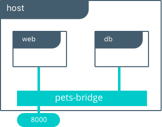
The application is exposed locally on this host on port 8000 on all
of its interfaces. Also supplied is DB=db, providing the name of the
backend container. The Mirantis Container Runtime’s built-in DNS resolves this
container name to the IP address of db. Since bridge is a local
driver, the scope of DNS resolution is only on a single host.
The output below shows us that our containers have been assigned private
IPs from the 172.19.0.0/24 IP space of the petsBridge network.
Docker uses the built-in IPAM driver to provide an IP from the
appropriate subnet if no other IPAM driver is specified.
$ docker inspect --format {{.NetworkSettings.Networks.petsBridge.IPAddress}} web
172.19.0.3

$ docker inspect --format {{.NetworkSettings.Networks.petsBridge.IPAddress}} db
172.19.0.2
These IP addresses are used internally for communication internal to the
petsBridge network. These IPs are never exposed outside of the host.
Multi-Host Bridge Driver with External Service Discovery
Because the bridge driver is a local scope driver, multi-host
networking requires a multi-host service discovery (SD) solution.
External SD registers the location and status of a container or service
and then allows other services to discover that location. Because the
bridge driver exposes ports for external access, external SD stores the
host-ip:port as the location of a given container.
In the following example, the location of each service is manually
configured, simulating external service discovery. The location of the
db service is passed to web via the DB environment variable.
# Create the backend db service and expose it on port 8500
host-A $ docker run -d -p 8500:8500 --name db consul

# Display the host IP of host-A
host-A $ ip add show eth0 | grep inet
    inet 172.31.21.237/20 brd 172.31.31.255 scope global eth0
    inet6 fe80::4db:c8ff:fea0:b129/64 scope link

# Create the frontend web service and expose it on port 8000 of host-B
host-B $ docker run -d -p 8000:5000 -e 'DB=172.31.21.237:8500' --name web chrch/docker-pets:1.0
The web service should now be serving its web page on port 8000
of host-B IP address.
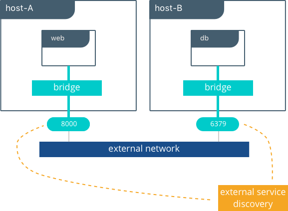
Note
In this example we don’t specify a network to use, so the default
Docker bridge network is selected automatically.
When we configure the location of db at 172.31.21.237:8500, we are
creating a form of service discovery. We are statically configuring the
location of the db service for the web service. In the single host
example, this was done automatically because Mirantis Container Runtime
provided built-in DNS resolution for the container names. In this multi-host
example we are doing the service discovery manually.
The hardcoding of application location is not recommended for production. External service discovery tools exist that provide these mappings dynamically as containers are created and destroyed in a cluster. Some examples are Consul and etcd.
The next section examines the overlay driver scenario, which
provides global service discovery across a cluster as a built-in
feature. This simplicity is a major advantage of the overlay driver,
as opposed to using multiple external tools to provide network services.
Multi-Host with Overlay Driver
This model utilizes the native overlay driver to provide multi-host
connectivity out of the box. The default settings of the overlay driver
provide external connectivity to the outside world as well as internal
connectivity and service discovery within a container application. The
Overlay Driver Architecture
section reviews the internals of the Overlay driver which you should
review before reading this section.
This example re-uses the previous docker-pets application. Set up a
Docker Swarm prior to following this example. For instructions on how to
set up a Swarm read the Docker
docs.
After the Swarm is set up, use the docker service create command to
create containers and networks to be managed by the Swarm.
The following shows how to inspect your Swarm, create an overlay network, and then provision some services on that overlay network. All of these commands are run on a MKE/swarm controller node.
# Display the nodes participating in this swarm cluster that was already created
$ docker node ls
ID                           HOSTNAME          STATUS  AVAILABILITY  MANAGER STATUS
a8dwuh6gy5898z3yeuvxaetjo    host-B  Ready   Active
elgt0bfuikjrntv3C33hr0752 *  host-A  Ready   Active        Leader

# Create the dognet overlay network
host-A $ docker network create -d overlay petsOverlay

# Create the backend service and place it on the dognet network
host-A $ docker service create --network petsOverlay --name db consul

# Create the frontend service and expose it on port 8000 externally
host-A $ docker service create --network petsOverlay -p 8000:5000 -e 'DB=db' \
           --name web chrch/docker-pets:1.0

host-A $ docker service ls
ID            NAME  MODE        REPLICAS  IMAGE
lxnjfo2dnjxq  db    replicated  1/1       consul:latest
t222cnez6n7h  web   replicated  1/1       chrch/docker-pets:1.0
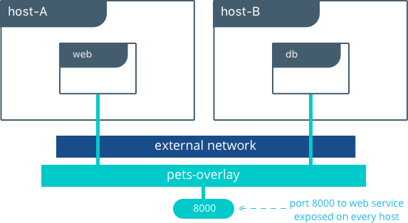
As in the single-host bridge example, we pass in DB=db as an
environment variable to the web service. The overlay driver resolves
the service name db to the db service VIP overlay IP address.
Communication between web and db occurs exclusively using the
overlay IP subnet.
Note
Inside overlay and bridge networks, all TCP and UDP ports to containers are open and accessible to all other containers attached to the overlay network.
The web service is exposed on port 8000, and the routing
mesh exposes port 8000 on every host in the Swarm cluster. Test if
the application is working by going to <host-A>:8000 or
<host-B>:8000 a the browser.
Overlay Benefits and Use Cases
- Very simple multi-host connectivity for small and large deployments
- Provides service discovery and load balancing with no extra configuration or components
- Useful for east-west micro-segmentation via encrypted overlays
- Routing mesh can be used to advertise a service across an entire cluster
Tutorial App: MACVLAN Bridge Mode
There may be cases where the application or network environment requires containers to have routable IP addresses that are a part of the underlay subnets. The MACVLAN driver provides an implementation that makes this possible. As described in the MACVLAN Architecture section, a MACVLAN network binds itself to a host interface. This can be a physical interface, a logical sub-interface, or a bonded logical interface. It acts as a virtual switch and provides communication between containers on the same MACVLAN network. Each container receives a unique MAC address and an IP address of the physical network that the node is attached to.
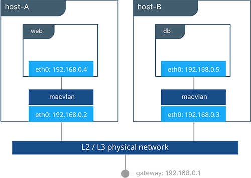
In this example, the Pets application is deployed on to host-A and
host-B.
# Creation of local macvlan network on both hosts
host-A $ docker network create -d macvlan --subnet 192.168.0.0/24 --gateway 192.168.0.1 \
           -o parent=eth0 petsMacvlan
host-B $ docker network create -d macvlan --subnet 192.168.0.0/24 --gateway 192.168.0.1 \
           -o parent=eth0 petsMacvlan

# Creation of db container on host-B
host-B $ docker run -d --net petsMacvlan --ip 192.168.0.5 --name db consul

# Creation of web container on host-A
host-A $ docker run -it --net petsMacvlan --ip 192.168.0.4 -e 'DB=192.168.0.5:8500' \
           --name web chrch/docker-pets:1.0
This may look very similar to the multi-host bridge example but there are a couple notable differences:
- The reference from
webtodbuses the IP address ofdbitself as opposed to the host IP. Remember that withmacvlancontainer IPs are routable on the underlay network. - We do not expose any ports for
dborwebbecause any ports opened in the container are immediately be reachable using the container IP address.
While the macvlan driver offers these unique advantages, one area
that it sacrifices is portability. MACVLAN configuration and deployment
is heavily tied to the underlay network. Container addressing must
adhere to the physical location of container placement in addition to
preventing overlapping address assignment. Because of this, care must be
taken to manage IPAM externally to a MACVLAN network. Overlapping IP
addressing or incorrect subnets can lead to loss of container
connectivity.
The MACVLAN driver can also be used with swarm services through the use of config-only local networks. For more information see the UCP User Guide.
MACVLAN Benefits and Use Cases
- Very low latency applications can benefit from the
macvlandriver because it does not utilize NAT. - MACVLAN can provide an IP per container, which may be a requirement in some environments.
- More careful consideration for IPAM must be taken into account.
Conclusion
Docker is quickly evolving, and the networking options are growing to satisfy more and more use cases every day. Incumbent networking vendors, pure-play SDN vendors, and Docker itself are all contributors to this space.
This document detailed some but not all of the possible deployments and CNM network drivers that exist. While there are many individual drivers and even more ways to configure those drivers, we hope you can see that there are only a few common models routinely deployed. Understanding the tradeoffs with each model is key to long term success.
Warning
Mirantis stopped maintaining this documentation set as of 2021-07-21, in correlation with the End of Life date for MKE 3.2.x and MSR 2.7.x. The company continues to support MCR 19.03.x and its documentation.
For the latest MKE, MSR, and MCR product documentation, refer to:
Security
Docker lives by “Secure by Default” with Docker Enterprise, the default configuration and policies provide a solid foundation for a secure environment. However, they can easily be changed to meet the specific needs of any organization.
Securing Docker Enterprise and Security Best Practices
Introduction
Docker lives by “Secure by Default.” With Docker Enterprise (DE), the default configuration and policies provide a solid foundation for a secure environment. However, they can easily be changed to meet the specific needs of any organization.
Docker focuses on three key areas of container security: secure access, secure content, and secure platform. This results in having isolation and containment features not only built into Docker Enterprise but also enabled out of the box. The attack surface area of the Linux kernel is reduced, the containment capabilities of the Docker daemon are improved, and admins build, share, and run safer applications.
What You Will Learn
This document outlines the default security of Docker Enterprise as well as best practices for further securing Mirantis Kubernetes Engine and Mirantis Secure Registry. New features introduced in Docker Enterprise 3.0 such as Image Mirroring and Kubernetes are also explored.
Prerequisites
- Docker Enterprise 3.0 (MKE 3.2.0, MSR 2.7.0, MCR 19.03.0) and higher on a Linux host OS with kernel 3.10-0.957 or greater
- Become familiar with Docker Concepts from the Docker docs
Abbreviations
The following abbreviations are used in this document:
| Abbreviation | Description |
|---|---|
| MKE | Mirantis Kubernetes Engine |
| MSR | Mirantis Secure Registry |
| RBAC | Role Based Access Control |
| CA | Certificate Authority |
| HA | High Availability |
| BOM | Bill of Materials |
| CLI | Command Line Interface |
| CI | Continuous Integration |
TL;DR
- Enable Selinux
- Enable FIPS - OS and MCR
- MKE/MSR is secure by default
- Always stay updated
- Enable Network Isolation with Network Security Policy for K8s.
- Establish a Secure Supply Chain
MCR and Node Security
There are already several resources that cover the basics of Mirantis Container Runtime security.
- Docker Security Documentation covers the fundamentals, such as namespaces and control groups, the attack surface of the Docker daemon, and other kernel security features.
- CIS Docker Community Edition Benchmark covers the various security-related options in MCR. Useful with Docker Enterprise.
- Docker Bench Security is a script that audits your configuration of MCR against the CIS Benchmark.
Choice of Operating Systems
Mirantis Container Runtime 19.03 (a required prerequisite for installing MKE and included with Docker Enterprise) is supported on the following host operating systems:
- RHEL/CentOS/Oracle Linux 7.6 or greater (YUM-based systems)
- Ubuntu 16.04, and 18.04 LTS
- SUSE Linux Enterprise 12sp4, and 15
For other versions, check out the official Docker support matrix.
To take advantage of built-in security configurations and policies, run the latest version of Mirantis Container Runtime. Also, ensure that the operating system is updated with all available patches. It is highly recommended to remove as much unnecessary software as possible to decrease attack surface within the environment.
Enable FIPS Mode
The Federal Information Processing Standards (FIPS) is a set of publications developed and maintained by the National Institute of Standards and Technology (NIST), a United States federal agency. These publications define the security criteria required for government computers and telecommunication systems.
According to NIST, FIPS 140-2 “specifies the security requirements that will be satisfied by a cryptographic module used within a security system protecting sensitive but unclassified information.”
More information can be found at https://www.nist.gov/…
Enable FIPS on RHEL/Centos
This probably will require a reboot.
$ sed -i 's/GRUB_CMDLINE_LINUX="/GRUB_CMDLINE_LINUX="fips=1 /g' /etc/default/grub
$ grub2-mkconfig -o /boot/grub2/grub.cfg
$ reboot
Enable FIPS in the Mirantis Container Runtime
Simply add a systmed file.
$ mkdir -p /etc/systemd/system/docker.service.d
$ echo -e "[Service]\n  Environment=\"DOCKER_FIPS=1\"" > \
    /etc/systemd/system/docker.service.d/fips-module.conf
$ systemctl daemon-reload
$ systemctl restart docker
Limit Root Access to Node
Docker Enterprise uses a completely separate authentication backend from the host, providing a clear separation of duties. Docker Enterprise can leverage an existing LDAP/AD infrastructure for authentication. It even utilizes RBAC Labels to control access to objects like images and running containers, meaning teams of users can be given full access to running containers. With this access, users can watch the logs and execute a shell inside the running container without needing to ever log into the host. Limiting the number of users that have access to the host reduces the attack surface.
Remote Access to Daemon
Do not enable the remote daemon socket. If you must open it for MCR, then ALWAYS secure the docker with certificates.
When using Mirantis Kubernetes Engine, you should not open the daemon socket. If you must, be sure to review the instructions for securing the daemon socket.
Privileged Containers
Avoid running privileged containers if at all possible. Running a container privileged gives the container access to ALL the host namespaces (i.e. net, pid, and others). This gives full control of the host to the container. Keep your infrastructure secure by keeping the container and host authentication separate.
Container UID Management
By default the user inside the container is root. Using a defense in
depth model, it is recommended that not all containers run as root. An
easy way to mitigate this is to use the --user declaration at run
time. The container runs as the specified user, essentially removing
root access.
Also keep in mind that the UID/GID combination for a file inside a
container is the same outside of the container. In the following
example, a container is running with a UID of 10000 and GID of 10000. If
the user touches a file such as /tmp/secret_file, on a BIND-mounted
directory, the UID/GID of the file is the same both inside and outside
of the container as shown:
$ docker run --rm -it -v /tmp:/tmp --user 10000:10000 alpine sh

$ whoami
whoami: unknown uid 10000

$ touch /tmp/secret_file

$ ls -asl /tmp/secret_file
     0 -rw-r--r--    1 10000    10000            0 Jan 26 13:48 /tmp/secret_file

$ exit

$ ls -asl /tmp/secret_file
0 -rw-r--r-- 1 10000 10000 0 Jan 26 08:48 /tmp/secret_file
Developers should use root as little as possible inside the
container. Developers should create their app containers with the
`USER <https://docs.docker.com/engine/reference/builder/#user>`__
declaration in their Dockerfiles.
Seccomp
Note
Seccomp for Mirantis Container Runtime is available starting with RHEL/CentOS 7 and SLES 12.
Seccomp (short for Secure Computing Mode) is a security feature of the Linux kernel, used to restrict the syscalls available to a given process. This facility has been in the kernel in various forms since MSR 2.6.12 and has been available in Mirantis Container Runtime since 1.10. The current implementation in Mirantis Container Runtime provides a default set of restricted syscalls and also allows syscalls to be filtered via either a whitelist or a blacklist on a per-container basis (i.e. different filters can be applied to different containers running in the same MCR). Seccomp profiles are applied at container creation time and cannot be altered for running containers.
Out of the box, Docker comes with a default Seccomp profile that works extremely well for the vast majority of use cases. In general, applying custom profiles is not recommended unless absolutely necessary. More information about building custom profiles and applying them can be found in the Docker Seccomp docs.
To check if your kernel supports seccomp:
$ cat /boot/config-`uname -r` | grep CONFIG_SECCOMP=
Look for the following in the output:
CONFIG_SECCOMP=y
AppArmor / SELinux
AppArmor and SELinux are security modules similar to Seccomp in their use of profiles, however they differ in how those profiles are executed. The profile languages used by AppArmor and SELinux are different, with AppArmor available for Debian-based distributions such as Debian and Ubuntu, and SELinux available on Fedora/RHEL/CentOS/Oracle Linux.
Rather than a simple list of system calls and arguments, both allow for defining actors (generally processes), actions (reading files, network operations), and targets (files, IPs, protocols, etc.). Both are Linux kernel security modules, and both support mandatory access controls (MAC).
They need to be enabled on the host, while SELinux can be enabled at the daemon level.
To enable SELinux in the Docker daemon, modify
/etc/docker/daemon.json and add the following:
{
  "selinux-enabled": true
}
To check if SELinux is enabled:
$ docker info --format '{{.SecurityOptions}}'
selinux should be in the output if it is enabled:
[name=seccomp,profile=default name=selinux name=fips]
AppArmor is not applied to the Docker daemon. Apparmor profiles need to be applied at container run time:
$ docker run \
    --interactive \
    --tty \
    --rm \
    --security-opt apparmor=docker-default \
    hello-world
Additional resources for installing and setting up AppArmor/SELinux include:
- Techmint - Implementing Mandatory Access Control with SELinux or AppArmor in Linux
- nixCraft - Linux Kernel Security (SELinux vs AppArmor vs Grsecurity)
Bottom line is that it is always recommended to use AppArmor or SELinux for their supported operating systems.
Runtime Privilege and Linux Capabilities — Advanced Tooling
Starting with kernel 2.2, Linux divides the privileges traditionally associated with superuser into distinct units, known as capabilities, which can be independently enabled and disabled. — Capabilities man page
Linux capabilities are an even more granular way of reducing surface area.
Mirantis Container Runtime has a default list of capabilities that are kept for
newly-created containers, and by using the --cap-drop option for docker
run, users can exclude additional capabilities from being used by processes
inside the container on a capability-by-capability basis. All privileges can be
dropped with the --user option.
Likewise, capabilities that are, by default, not granted to new
containers can be added with the --cap-add option. This is
discouraged unless absolutely necessary, and using --cap-add=ALL is
highly discouraged.
More details can be found in the Docker Run Reference.
Controls from the CIS Benchmark
There are many good practices that should be applied from the CIS
Docker Community Edition Benchmark
v1.2.0. Please keep in
mind that the Benchmarks are written for a single engine only.
Understanding that some of the controls may not be applicable to Docker
Enterprise. Lets look at some good ones for Docker Enterprise. To apply
these controls, edit the MCR settings. Editing the MCR setting in
/etc/docker/daemon.json is the best choice for most of these
controls. Refer to the daemon.json
guide
for details.
Ensure centralized and remote logging is configured
CIS CE Benchmark v1.2.0 : Section 2.12
Having a central location for all MCR and container logs is recommended. This provides “off-node” access to all the logs, empowering developers without having to grant them SSH access.
To enable centralized logging, modify /etc/docker/daemon.json and
add the following:
{
"log-level": "syslog",
"log-opts": {
"syslog-address": "udp://1.2.3.4:1111"
}
}
Then restart the daemon:
$ sudo systemctl restart docker
Enable Content Trust
CIS CE Benchmark v1.2.0 : Section 4.5
Content Trust is the cryptographic guarantee that the image pulled is the correct image. Content Trust is enabled by the Notary project, a part of the Cloud Native Computing Foundation (CNCF). Signing images with Notary is discussed later in this document.
When transferring data amongst networked systems, trust is a central concern. When communicating over an un-trusted medium such as the Internet, it is critical to ensure the integrity and the publisher of all data involved in operating a system. Mirantis Container Runtime is used to push and pull images (data) to a public or private registry. Content Trust provides the ability to verify both the integrity and the publisher of all data received from a registry over any channel. Content Trust is available on Docker Hub or DTR 2.1.0 and higher. To enable it, add the following shell variable:
$ export DOCKER_CONTENT_TRUST=1
Audit with Docker Bench
Docker Bench
Security
is a script that checks for dozens of common best practices around
deploying Docker containers in production. Docker Bench Security is
designed for auditing a single node deployment and not a SWARM cluster.
The tests are all automated and are inspired by the CIS Docker
Benchmark v1.1.0.
Here is how to run it :
$ docker run -it \
--net host \
--pid host \
--userns host \
--cap-add audit_control \
-e DOCKER_CONTENT_TRUST=$DOCKER_CONTENT_TRUST \
-v /var/lib:/var/lib \
-v /var/run/docker.sock:/var/run/docker.sock \
-v /usr/lib/systemd:/usr/lib/systemd \
-v /etc:/etc --label docker_bench_security \
docker/docker-bench-security
Here is example output:
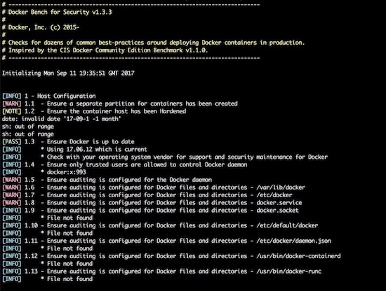
The output is straightforward, providing a status message, CIS Benchmark
Control number, and description fields. Pay special attention to the
[WARN] messages, and 1 - Host Configuration section. Also, keep
in mind that while Docker Bench is designed to audit MCR, it
is not intended for auditing the setup of Mirantis Kubernetes Engine (MKE)
and Mirantis Secure Registry (MSR). There are a few controls that, when
enabled, break MKE and MSR.
The following controls are not needed because they affect the operation of MKE/MSR:
| Control | Description | Impact |
|---|---|---|
| 2.1 | Restrict network traffic between containers | Needed for container communication |
| 2.6 | Configure TLS authentication for Docker daemon | Should not be enabled as it is not needed |
| 2.8 | Enable user namespace support | Currently not supported with MKE/MSR |
| 2.15 | Disable Userland Proxy | Disabling the proxy affects how the routing mesh works |
| 5.4 | Ensure privileged containers are not used | MKE requires privileged contianers |
Windows Engine and Node Security
Beginning with Docker Engine 17.06, Docker Enterprise includes native Windows Server support. Docker Enterprise may be installed on a Windows Server node and then joined into a cluster managed by Mirantis Kubernetes Engine (MKE). Currently, only Windows worker nodes are supported, with manager nodes being deployed on Linux.
A MKE cluster with mixed worker nodes provides the capability to manage
both Linux-based and Windows-based workloads within the same
orchestration framework. Additionally, while Linux can only run
containers with the traditional process isolation mode, Windows
Server includes a second hyperV isolation mode. This mode
encapsulates Docker containers with a slim Hyper-V virtual machine,
providing additional isolation and security for the workload.
Some of the advantages of Windows worker nodes include:
- Eliminates conflicts between different versions of IIS/.NET to coexist on a single system with container isolation
- Works with Hyper-V virtualization
- Takes advantage of new base images like Windows Server Core and Nano Server
- Provides a consistent Docker user experience — use the same commands as Docker for Linux environments
- Adds isolation properties with Hyper V containers selected at runtime
For more information about installing Docker Enterprise on Windows Server, follow the documentation.
Mirantis Kubernetes Engine (MKE) Security
This section will cover Mirantis Kubernetes Engine (MKE). MKE follows the same default posture of “Secure by Default”. For example MKE out of the box delivers with two Certificate Authorities (CA) with Mutual TLS. The two CAs set up by MKE include:
- The first CA is used for ALL internal communication between managers and workers
- The second CA is for the end user communication.
Bifurcating the two communication paths is vital to keeping data traffic segregated, while Mututal TLS enables both the client and service to verify each others’ identify. While complex to setup in other systems, the use of Mutual TLS is automatically configured between the manager and worker nodes by MKE.
Worker nodes are unprivileged, meaning they do not have access to the cluster state or secrets. When adding nodes to the MKE cluster, a join token must be used. The token itself incorporates the checksum of the CA cert so the new node can verify that it is communicating with the proper cluster.

Kubernetes

The same “Secure by Default” approach is applied by Docker Enterprise to the built-in Kubernetes orchestrator. For reference please review external guidance on security from kubernetes-security.info. All the recommendations have already been applied. From a security point of view this is the best of both worlds, as Docker Enterprise provides user authentication and RBAC on top of Kubernetes. To ensure the Kubernetes orchestrator follows all the security best practices, MKE utilizes TLS for the Kubernetes API port. When combined with MKE’s authentication model, this allows the same client bundle to talk to the Swarm or Kubernetes API.
For the configuration of Kubernetes, it is recommended that you follow the CIS Kubernetes Benchmark.
In order to deploy Kubernetes within Docker Enterprise, the nodes need to be setup and configured. While a node may be configured in “Mixed Mode” to concurrently participate in both Swarm and Kubernetes orchestrators, it is advised to specify a single orchestrator. This avoids an issue where each orchestrator tries to control the containers on that node without knowledge of the resources used by the other orchestrator. Manager nodes are the exception, operating in Mixed Mode to ensure all components for both orchestrators are highly available.

To set a node’s orchestrator, navigate to Shared Resources -> Nodes -> select the node you want to change. Next select the Configure -> Details. From there select KUBERNETES and save. Notice the warning that all the Swarm workloads will be evicted.

In addition to setting individual nodes for Kubernetes. MKE allows for all new nodes to be set to a specific orchestrator. To set the default orchestrator for new nodes navigate to Admin Settings -> Scheduler, select Kubernetes, and save.

Pod Security Policy
Pod Security Policies (PSPs) are cluster-level resources which are enabled by default in Mirantis Kubernetes Engine (MKE) 3.2. See Pod Security Policy for an explanation of this Kubernetes concept. Kubernetes Docs - Pod Security Policy has more information.
There are two default PSPs in MKE: a privileged policy and an unprivileged policy. Administrators of the cluster can enforce additional policies and apply them to users and teams for further control of what runs in the Kubernetes cluster. This guide describes the two default policies, and provides two example use cases for custom policies.
To interact with PSPs, a user will need to be granted access to the PodSecurityPolicy object in Kubernetes RBAC. If the user is a MKE Admin, then the user can already manipulate PSPs. A normal user can interact with policies if a MKE admin creates the following ClusterRole and ClusterRoleBinding:
$ cat <<EOF | kubectl create -f -
apiVersion: rbac.authorization.k8s.io/v1
kind: ClusterRole
metadata:
name: psp-admin
rules:
- apiGroups:
- extensions
resources:
- podsecuritypolicies
verbs:
- create
- delete
- get
- list
- patch
- update
EOF
$ cat <<EOF | kubectl create -f -
apiVersion: rbac.authorization.k8s.io/v1
kind: ClusterRoleBinding
metadata:
name: psp-admin:$USER
roleRef:
kind: ClusterRole
name: psp-admin
apiGroup: rbac.authorization.k8s.io
subjects:
- kind: User
name: $USER
EOF
By default, there are two policies defined within MKE, privileged and unprivileged. Additionally, there is a ClusterRoleBinding that gives every single user access to the privileged policy. This is for backward compatibility after an upgrade. By default, any user can create any pod.
More information can be found at docs.docker.com/ee/ucp/kubernetes/pod-security-policies/
Network Security Policy
Network Security Policy (NSP) is a great way to isolate pods from a network level. Here is an example for isolating network traffic to each namespace.
# Network Policy
# Deny All Network Policy for the Namespace
kind: NetworkPolicy
apiVersion: networking.k8s.io/v1
metadata:
name: default-deny
spec:
podSelector:
matchLabels: {}
---
# Only accept traffic from all local pods in the namespace
kind: NetworkPolicy
apiVersion: networking.k8s.io/v1
metadata:
name: allow-local-namespace-pods
spec:
podSelector:
matchLabels:
ingress:
- from:
- podSelector: {}
---
# Allow ingress
kind: NetworkPolicy
apiVersion: networking.k8s.io/v1
metadata:
name: allow-infra-traffic-to-namespace
spec:
podSelector:
matchLabels: {}
ingress:
- from:
- namespaceSelector:
matchLabels:
name: ingress-nginx
Ideally, limiting all network traffic to the namespace and ingress is a great way to decrease the network surface area. Kubernetes Docs - Network Security Policy has more information.
Verification with Kube-Hunter
Validation is always great in any system. Aqua has opensource a tooled called kube-hunter. Kube-hunter is good tool for scanning clusters to validate the level of security. Here is the output of running kube-hunter against an install of Docker Enterprise 3.0 (MKE 3.2.1, MSR 2.7.2, MCR 19.03.2).
$ docker run -it --rm --network host aquasec/kube-hunter --remote ucp.dockr.life
~ Started
~ Discovering Open Kubernetes Services...
|
| Kubelet API:
| type: open service
| service: Kubelet API
|_ location: ucp.dockr.life:10250
|
| Unrecognized K8s API:
| type: open service
| service: Unrecognized K8s API
|_ location: ucp.dockr.life:6443
----------
Nodes
+-------------+----------------+
| TYPE | LOCATION |
+-------------+----------------+
| Node/Master | ucp.dockr.life |
+-------------+----------------+
Detected Services
+----------------------+----------------------+----------------------+
| SERVICE | LOCATION | DESCRIPTION |
+----------------------+----------------------+----------------------+
| Unrecognized K8s API | ucp.dockr.life:6443 | A Kubernetes API |
| | | service |
+----------------------+----------------------+----------------------+
| Kubelet API | ucp.dockr.life:10250 | The Kubelet is the |
| | | main component in |
| | | every Node, all pod |
| | | operations goes |
| | | through the kubelet |
+----------------------+----------------------+----------------------+
No vulnerabilities were found
Validating the cluster is Secure by Default is a good thing.
Networking
Networking is an important part of any Docker Enterprise deployment. Whether deploying to a public cloud infrastructure or to an on-premises datacenter, low latency between nodes is a must to ensure the distributed databases are able to keep quorum. Latency requirements are published as part of the MKE System Requirements.
Firewalls are generally avoided between the manager and worker nodes to minimize connectivity issues. When a software or hardware firewall is deployed between the nodes, the ports specified in the MKE System Requirements documentation need to be opened.
Authentication
Docker Enterprise features a single sign-on for the entire cluster, which is accomplished via shared authentication service for MKE and MSR. The single sign-on is provided out of the box with AuthN or via an externally-managed LDAP/AD authentication service. Both authentication backends provide the same level of control. When available, a corporate LDAP service can provide a smoother account experience for users. Refer to the LDAP/AD configuration docs and Docker Enterprise Best Practices and Design Considerations for instructions and best practices while configuring LDAP authentication.
To change the authentication to LDAP, go to Admin -> Admin Settings -> Authentication & Authorization in the MKE web interface.
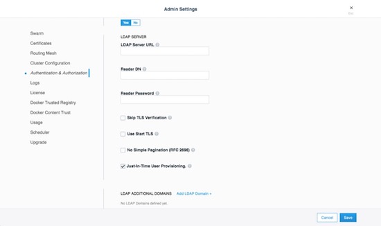
MKE External Certificates
Using external certificates is a recommended when integrating with a
corporate environment. Using external, officially-signed certificates
simplifies having to distribute internal Certificate Authority (CA)
certificates. One best practice is to use the Certificate Authority for
your organization. Reduce the number of certificates by adding multiple
Subject Alternative Names (SANs) to a single certificate. This allows
the certificate to be valid for multiple URLs. For example, you can set
up a certificate for mke.example.com, dtr.example.com, and all
the underlying hostnames and IP addresses. One certificate/key pair
makes deploying certs easier.
To add an external certificate, go to Admin -> Admin Settings -> Certificates in the MKE web interface and add the CA, Cert, and Key.

More detailed instructions for adding external certificates are available in the Docker docs.
Join Token Rotation
Depending on how the swarm cluster is built, it is possible to have the join token stored in an insecure location. To alleviate any concerns, join tokens can be rotated after the cluster is built. To rotate the keys, go to the Admin -> Admin Settings -> Swarm page, and click the Rotate button.
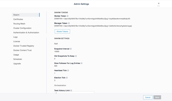
Node Certificate Expiration
Mirantis Kubernetes Engine’s management plane uses a private CA and certificates for all internal communication. The client certificates are automatically rotated on a schedule, providing a strong method for reducing the effect of a compromised node. There is an option to reduce the default time interval of 90 days to a shorter interval, however shorter intervals do add stress to the MKE cluster. To adjust the certificate rotation schedule, go to Admin -> Admin Settings -> Swarm and scroll down.
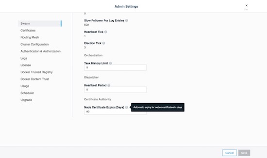
Client Bundles and PKI x509
As of Mirantis Kubernetes Engine 3.2.0 Public-Key Infrastructure ( PKI ) is now fully supported. For those not sure about PKI take a look at the wikipedia entry page. Mirantis Kubernetes Engine makes it easy to create a client certificate bundle for use with the Docker client if you don’t already have a PKI system. The client bundle allows end users to securely connect from a Docker Client to MKE via certificates when deploying workloads and administering the environment.
To enable PKI with MKE navigate to Admin Settings -> Certificates. Scroll down to Client CA. Paste in any and all Root Client CAs and Intermediates as needed.
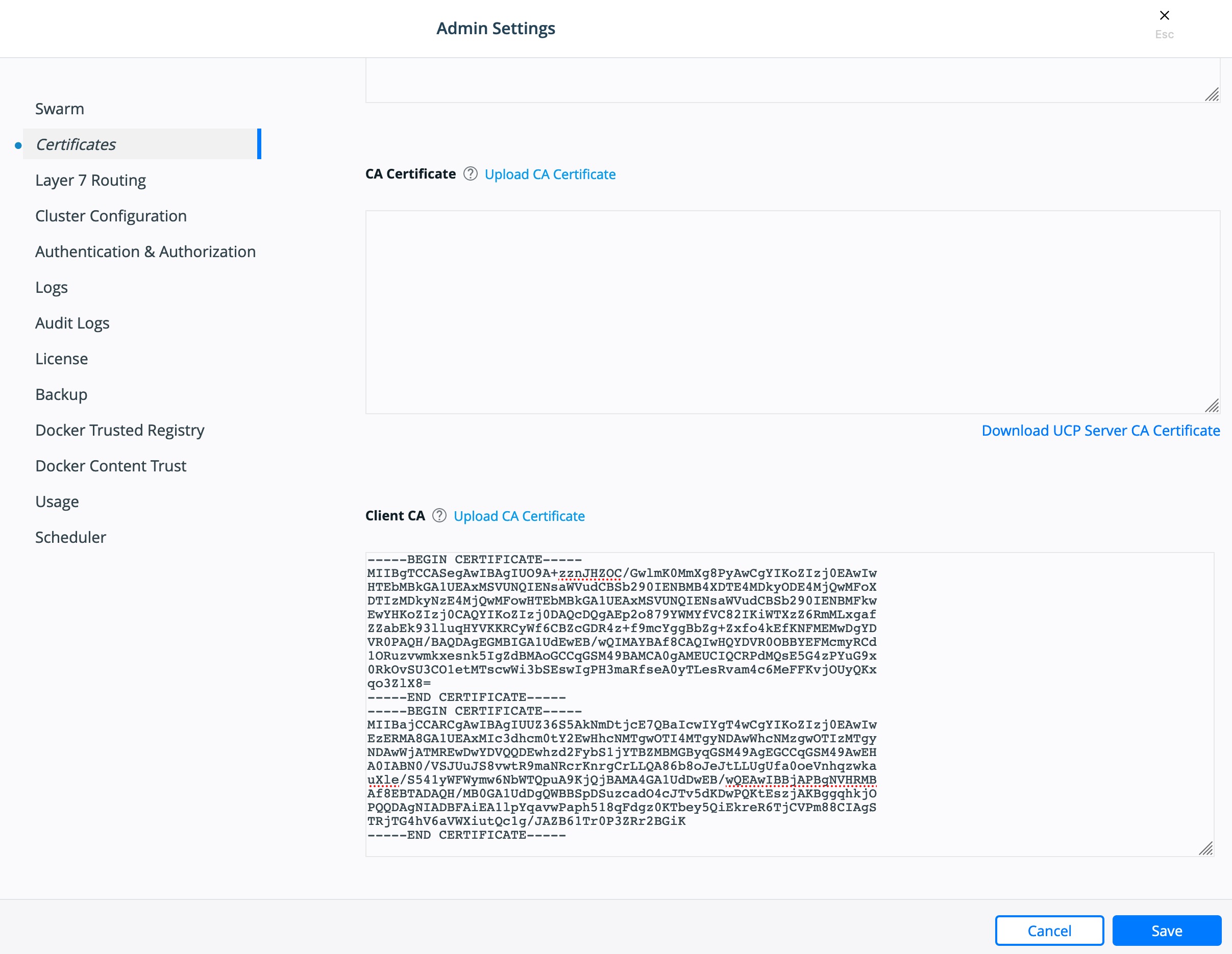
Click Save.
To create a client bundle, log into MKE, and click the login name in the upper left. Then select My Profile -> Client Bundles.

Selecting New Client Bundle with create and download a zipped bundle. Inside the bundle are the files necessary for talking to the MKE cluster directly.
Navigate to the directory where you downloaded the user bundle, and unzip it.
$ unzip ucp-bundle-admin.zip
Then run the env.sh script:
$ eval $(<env.sh)
On Windows, the bundle may be imported with PowerShell:
> Import-Module .\env.ps1
Verify the changes:
$ docker info
The env.sh script updates the DOCKER_HOST environment variable
to make your local Docker CLI communicate with MKE. It also updates the
DOCKER_CERT_PATH environment variable to use the client certificates
that are included in the client bundle you downloaded.
After setting up a client bundle, the Docker CLI client will include the
client certificates as part of the request to the Docker engine. The
Docker CLI can now be used to create services, networks, volumes, and
other resources on a swarm managed by MKE. The Kubernetes CLI tool,
kubectl, will also be configured for programmatic access to the
Kubernetes API within MKE.
To stop talking to the MKE cluster, restart the terminal or run the following command:
$ unset DOCKER_HOST DOCKER_TLS_VERIFY DOCKER_CERT_PATH
Run docker info to verify that the Docker CLI is communicating with
the local daemon.
To import your own existing certificate. Please make sure the Client Certificate has been configured.

Cluster Role-Based Access Control
The Access Control model within Docker Enterprise provides an extremely fine-grained control of what resources users can access within a cluster. Use of role based access controls (RBAC) is highly recommended for a secure cluster. Security principles of least privilege dictate the use of access control to limit access to resources whenever possible.
Access Control Policy
Docker Enterprise Access Control is a policy-based model that uses access control lists (ACLs) called grants to dictate access between users and cluster resources. A grant ties together who, has permission for which actions, against what resource. They are a flexible way of implementing access control for complex scenarios without incurring high management overhead for the system administrators.
As shown below, a grant is made up of a subject (who), role (which permissions), and a collection (what resources).

Note
It is the MKE administrators’ responsibility to create and manage the grants, subjects, roles, and collections.
Subjects
A subject represents a user, team, or organization. A subject is granted a role for a collection of resources. These groups of users are the same across MKE and MSR making RBAC management across the entire software pipeline uniform.
| Subject | Description |
|---|---|
| User | A single user or system account that an authentication backend (AD/LDAP) has validated. |
| Team | A group of users that share a set of permissions defined in the team itself. A team exists only as part of an organization, and all team members are members of the organization. A team can exist in one organization only. Assign users to one or more teams and one or more organizations. |
| Organization | The largest organizational unit in Docker Enterprise. Organizations group together teams to provide broader scope to apply access policy against. |
Roles and Permissions
A role is a set of permitted API operations that may be assigned to a specific subject and collection by using a grant. Roles define what operations can be done against cluster resources. An organization will likely use several different kinds of roles to give the right kind of access. A given team or user may have different roles provided to them depending on what resource they are accessing. There are default roles provided by MKE, and there is also the ability to build custom roles.
Docker Enterprise defines granular roles down to the Docker API level to match unique requirements that an organization may have. Define roles with authorized API operations has a full list of the operations that can be used to build new roles.
For example, a custom role called developer could be created to allow developers to view and retrieve logs from their own containers that are deployed in production. A developer cannot affect the container lifecycle in any way but can gather enough information about the state of the application to troubleshoot application issues.
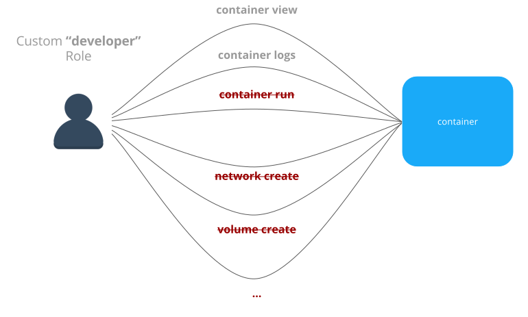
MKE also provides default roles that are pre-created. These are common role types that can be used to ease the burden of creating custom roles.
| Built-In Role | Description |
|---|---|
| None | The user has no access to swarm resources. This maps to the No Access role in UCP 2.1.x. |
| View Only | The user can view resources like services, volumes, and networks but can’t create them. |
| Restricted Control | The user can view and edit volumes, networks, and images but can’t run a service or container in a way that might affect the node where it’s running. The user can’t mount a node directory and can’t exec into containers. Also, the user can’t run containers in privileged mode or with additional kernel capabilities. |
| Scheduler | The user can view nodes and schedule workloads on them. Worker nodes and
manager nodes are affected by Scheduler grants. Having Scheduler
access doesn’t allow the user to view workloads on these nodes. They
need the appropriate resource permissions, like Container View. By
default, all users get a grant with the Scheduler role against the
/Shared collection. |
| Full Control | The user can view and edit volumes, networks, and images. They can create containers without any restriction but can’t see other users’ containers. |
Collections
Docker Enterprise enables controlling access to swarm resources by using collections. A collection is a grouping of swarm cluster resources that you access by specifying a directory-like path. Before grants can be implemented, collections need to be designed to group resources in a way that makes sense for an organization.
The following example shows the potential access policy of an organization. Consider an organization with two application teams, Mobile and Payments, that share cluster hardware resources, but still need to segregate access to the applications. Collections should be designed to map to the organizational structure desired, in this case the two application teams.
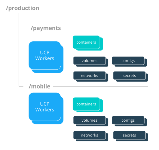
Note
Permissions to a given collection are inherited by all children of that collection.
Collections are implemented in MKE through the use of Docker labels. All
resources within a given collection are labeled with the collection,
/production/mobile for instance.
Collections are flexible security tools because they are hierarchical. For instance, an organization may have multiple levels of access. This might neccessitate a collection architecture like the following:
├── production
│ ├── database
│ ├── mobile
│ └── payments
│ ├── restricted
│ └── front-end
└── staging
├── database
├── mobile
└── payments
├── restricted
└── front-end
To create a child collection, navigate into the parent collection. Then create the child.

To add objects to collections, leverage labels. When deploying a stack make sure all objects are “labeled.” Here is a good example of a few labels :
- Add an object to the
/productioncollection:com.docker.ucp.access.label: "/production" - Add an object to the
/production/mobilecollection:com.docker.ucp.access.label: "/production/mobile"
Adding nodes to a collection takes a little more care. Please follow the documentation for isolating nodes to specific teams. Isolating nodes is a great way to provide more separation for multi-tenant clusters.
Grant Composition
When subjects, collections, and roles are setup, grants are created to map all of these objects together into a full access control policy. The following grant is one of many that might be created:
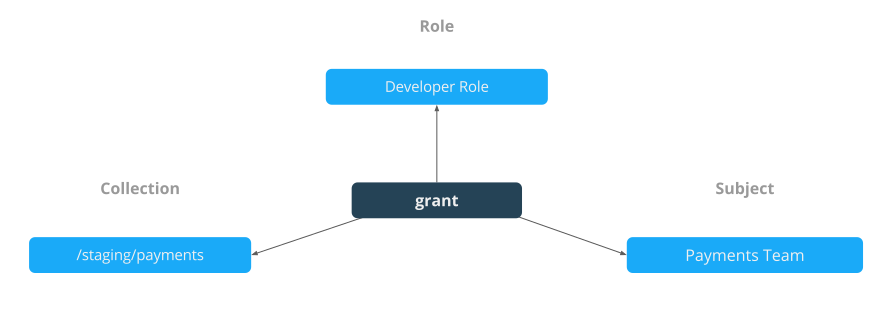
Together, the grants clearly define which users have access to which resources. This is a list of some of the default grants in MKE that exist to provide an admin the appropriate access to MKE and MSR infrastructure.

Secrets
A Docker secret is a blob of sensitive data that should not be transmitted over a network, such as:
- Usernames and passwords
- TLS certificates and keys
- SSH keys
- Other important data such as the name of a database or internal server
- Generic strings or binary content (up to 500 kb in size)
Such sensitive data is often stored unencrypted in a Dockerfile or stored in an application’s source code. It is recommended to transition such data to Docker secrets to centrally manage this data and securely transmit it only to those containers that require access. Secrets follow a Least Privileged Distribution model, and are encrypted at rest and in transit in a Docker swarm. A given secret is only accessible to those services which have been granted explicit access and only while those service tasks are running.
Note
Docker secrets are only available to swarm services, not to standalone containers. To use this feature, consider adapting the container to run as a Docker service with a scale of 1.
Another use case for using secrets is to provide a layer of abstraction between the container and a set of credentials. Consider a scenario where separate development, test, and production environments are used for an application. Each of these environments can have different credentials, stored in the development, test, and production swarms with the same secret name. The containers only need to know the name of the secret to function in all three environments.
When a secret is added to the swarm, Docker sends the secret to the swarm manager over a mutual TLS connection. The secret is stored in the Raft log, which is encrypted. The entire Raft log is replicated across the other managers, ensuring the same high availability guarantees for secrets as for the rest of the swarm management data.
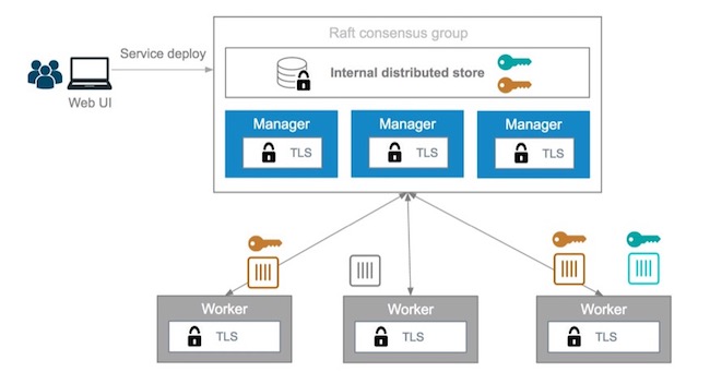
When a newly-created or running service is granted access to a secret,
the decrypted secret is mounted into the container in an in-memory
filesystem at /run/secrets/<secret_name>. It is possible to update a
service to grant it access to additional secrets or revoke its access to
a given secret at any time.
Note
Since Windows Server does not include a similar in-memory disk
mechanism, the secret will be written to its disk at
C:\ProgramData\Docker\secrets. For this reason it is recommended
to use a disk encryption technique such as BitLocker
A node only has access to (encrypted) secrets if the node is a swarm manager or if it is running service tasks which have been granted access to the secret. When a container task stops running, the decrypted secrets shared to it are unmounted from the in-memory filesystem for that container and flushed from the node’s memory.
If a node loses connectivity to the swarm while it is running a task container with access to a secret, the task container still has access to its secrets but cannot receive updates until the node reconnects to the swarm.
Docker Enterprise’s strong RBAC system can tie secrets into it with the exact same labels demonstrated before, meaning you should always limit the scope of each secret to a specific team. If there are NO labels applied, the default label is the owner.
For example, TLS certificates can be added as secrets. Using the same
RBAC example teams as previously mentioned, the following example adds
ca.pem, cert.pub, and cert.pem to the secrets vault. Notice
the use of the label com.docker.ucp.access.label=/prod. This is
important for enforcing the RBAC rules. Also note the use of the team
name in the naming of the secret. For another idea for updating or
rolling back secrets, consider adding a version number or date to the
secret name. This is made easier by the ability to control the mount
point of the secret within a given container. This also prevents teams
from trying to use the same secret name. Secrets can be found under the
Swarm menu. The following adds the CA’s public certificate in pem
format as a secret named orcabank_prod_mobile.ca.pem.v1.
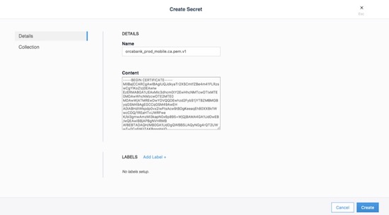
Next, set the collection the secret is in. Using the same example from
above, select the /prod collection.

Secrets are only available to services. The following creates an
nginx service. The service and the secret MUST be in the same
collection. Again, apply the collection through the use of labels. If
they don’t match, MKE won’t allow you to deploy. The next example
deploys a service that can be used as a secret:
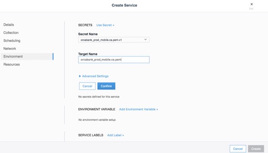
The important part is on the Environment tab. Click the + Use a secret. Use the advanced settings to configure the UID/GID and file mode for the secret when it is mounted. Binaries and tarballs can be added as secrets, with a file size up to 500KB. Be sure to click Confirm to add the secret.
When using the CLI, the option, --secret source=,target=,mode= needs
to be added to the docker service create command as follows:
$ docker service create \
--label com.docker.ucp.access.label=/prod \
--name nginx \
--publish 443 \
--secret source=orcabank_prod_mobile.ca.pem.v1,target=ca.pem \
--secret source=orcabank_prod_mobile.cert.pub.v1,target=cert.pub \
--secret source=orcabank_prod_mobile.cert.pem.v1,target=cert.pem \
nginx
Notice that the secrets are mounted to /run/secrets/. Because of
labels in this example, only administrators and the crm team have access
to this container and its secrets.
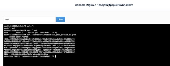
Changing secrets is as easy as removing the current version and creating it again. Be sure the labels on the new secret are correct.
Logging
Mirantis Kubernetes Engine (MKE) is deployed as a containerized application, automatically using the Mirantis Container Runtime’s logging configuration. For more information on logging see Docker Logging Design and Best Practices.
OSCAL - Experimental
As of Docker Enterprise 3.0 Mirantis Kubernetes Engine is shipping with Open Security Controls Assessment Language (OSCAL) as an experimental feature. The Open Security Controls Assessment Language (OSCAL) is a set of standardized XML- and JSON-based formats developed by the National Institute of Standards and Technology (NIST) for reporting, implementing, and assessing system security controls. Docker Enterprise contains OSCAL integrations for automating attestation and reporting requirements of your container platform. Use the OSCAL integrations to automatically:
- Assess system compliance.
- Correct system configurations that have drifted and are non-compliant.
- Download Docker’s officially signed and maintained OSCAL-formatted attestation artifacts that describe how Docker’s products adhere to and can be configured to meet compliance standards and hardening benchmarks.
These OSCAL auditing and reporting capabilities are exposed via OSCAL API endpoints built into MKE and enabled by default. Capabilities also include the majority of the recommendations in the CIS Kubernetes Benchmark, along with a subset of the CIS Docker Benchmark checks that are currently performed by the external. Mirantis Kubernetes Engine ships with a well documented api.
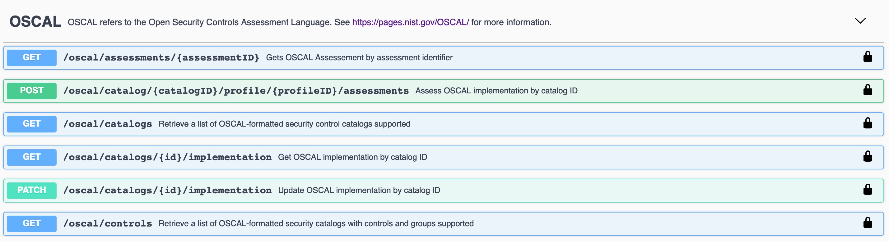
Get Catalog Version
$ token=$(curl -sk -d '{"username":"admin","password":"<PASSWORD>"}' https://<MKE_URL>/auth/login | jq -r .auth_token)
$ curl -skX GET "https://<MKE_URL>/oscal/catalogs" -H "Authorization: Bearer $token" -H "accept: application/json" | jq .
[
{
"id": "NIST_800-53",
"modelVersion": "Revision 4",
"title": "This NIST SP 800-53 database represents the security controls and associated assessment procedures defined in NIST SP 800-53 Revision 4 Recommended Security Controls for Federal Information Systems and Organizations",
"declarations": {
"href": "https://nvd.nist.gov/800-53"
}
}
]
Get Controls
Here is a truncated output from the list of controls.
$ token=$(curl -sk -d '{"username":"admin","password":"<PASSWORD>"}' https://<MKE_URL>/auth/login | jq -r .auth_token)
$ curl -skX GET "https://ucp.dockr.life/oscal/controls" -H "Authorization: Bearer $token" -H "accept: application/json" | jq .
[
{
"title": "NIST SP800-53",
"groups": [
{
"id": "Access Control",
"controls": [
{
"id": "ac-2",
"class": "SP800-53",
"title": "Account Management",
"subcontrols": [...
There is a lot more work to be done on displaying and auditing the individual controls. Please standby.
MSR Security
Mirantis Secure Registry continues the “Secure by Default” theme with two new strong features: Image Signing (via the Notary project) and Image Scanning. Additionally, MSR shares authentication with MKE, which simplifies setup and provides strong RBAC without any effort.
MSR stores metadata and layer data in two separate locations. The metadata is stored locally in a database that is shared between replicas. The layer data is stored in a configurable location.
Public-Key Infrastructure (PKI) Integration
In order to take advantage of Public-Key Infrastructure (PKI) for
docker push and docker pull MSR needs to be configured.
Configuring MSR is from the command line.
$ docker run --rm -it docker/dtr:2.7.2 reconfigure --ucp-url ucp.dockr.life --ucp-username admin \
--ucp-password <PASSWORD> --enable-client-cert-auth --client-cert-auth-ca "$(cat < orig.ca.pem)" \
--ucp-insecure-tls
Similar to MKE the file should include all Root and Intermediate certificates. Once configured the client will still need to be configured.
PKI Push and Pull
To configure the docker daemon it is suggested to remove the
~/.docker/config.json authentication file. This will ensure the
client will only use PKI for authentication. Simply copy the certificate
and key to /etc/docker/certs.d/<FQDN>/
Example:
$ ls -asl /etc/docker/certs.d/dtr.dockr.life/
total 12
0 drw-r--r--. 2 root root 69 Sep 9 16:32 .
0 drw-r--r--. 3 root root 28 Sep 9 12:05 ..
4 -rw-r--r--. 1 root root 741 Sep 28 2018 client.cert
4 -rw-------. 1 root root 227 Sep 28 2018 client.key
4 -rw-r--r--. 1 root root 725 Sep 9 12:05 dtr.dockr.life.crt
Once configured all docker push and docker pull commands will
use the PKI certificates for authentication.
MSR External Certificates
Similar to MKE, MSR can use either the default self-signed certificates,
or fully-signed company certificates sourced from an existing corporate
Certificate Authority (CA). To reduce the number of certificates, add
multiple Subject Alternative Names (SANs) to a single certificate. This
allows the certificate to be valid for multiple URLs. For example, when
setting up a certificate for mke.example.com, add SANs of
dtr.example.com and all the underlying hostnames and IP addresses.
Using this technique allows the same certificate to be used for both MKE
and MSR.
External certificates are added to MSR by going to System -> General -> Domain & proxies -> Show TLS Settings.
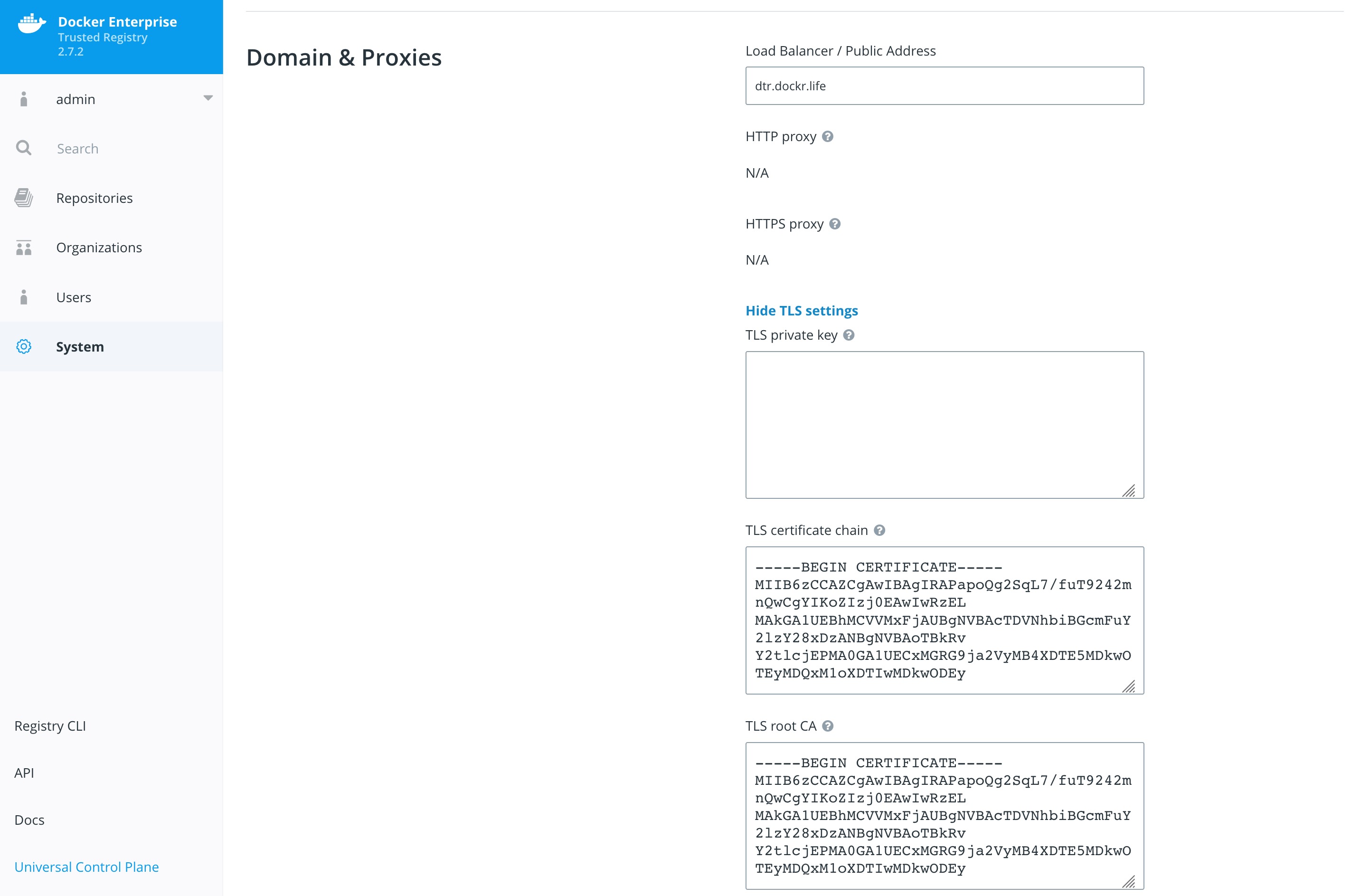
For more instructions on adding external certificates, refer to the Docker docs.
Storage Backend
The choice of the storage backend for MSR has effects on both performance and security. The choices include:
| Type | Advantages | Disadvantages |
|---|---|---|
| Local Filesystem | Fast and Local. Pairs great with local block storage. | Requires bare metal or ephemeral volumes. NOT good for HA. |
| S3 | Great for HA and HTTPS communications. Several third party servers available. Can be encrypted at rest. | Requires maintaining or paying for an external S3 compliant service. |
| Azure Blob Storage | Can be configured to act as local but have redundancy within Azure Storage. Can be encrypted at rest. | Requires Azure cloud account. |
| OpenStack Swift | Similar to S3 being an object store. | Requires OpenStack infrastructure for service. |
| Google Cloud Storage | Similar to S3 being an object store. Can be encrypted at rest. | Requires a Google Cloud account. |
| NFS | Easy to setup/integrate with existing infrastructure. | Slower due to network calls. |
To change the settings, go to System -> Storage in MKE.

Storage choice is highly influenced by where Docker Enterprise is deployed; place MSR’s backend storage as close as possible to MSR itself. Always ensure that HTTPS (TLS) is being used. Also, consider how to backup MSR’s images. When in doubt, use a secure object store, such as S3 or similar. Object stores provide the best balance between security and ease of use and also make it easy for highly available (HA) MSR setups.
Garbage Collection
Garbage collection is an often-overlooked area from a security standpoint. Old, out-of-date images may contain security flaws or exploitable vulnerabilities; removing unnecessary images is important. Garbage collection is a feature that ensures that unreferenced images (and layers) are removed.
To scheduling the current Garbage Collection navigate to System -> Garbage Collection. The current best practices is to create a schedule for every Saturday or Sunday and Until Done. Click Save & Start.

Organizations and Teams — RBAC
Since Mirantis Kubernetes Engine and Mirantis Secure Registry utilize the same authentication backend, users are shared between the two. This simplifies user management since UCP and MSR organizations are now shared. That means MKE and MSR can manage the organizations and teams. Consider the differences between organizations and teams. Teams are nested underneath organizations. Teams allow for a finer grain control of access.
Here’s an overview of the permission levels available for organizations and users:
- Anonymous users: Search and pull public repositories.
- Users: Search and pull public repos. Create and manage their own repositories.
- Team member: Can do everything a user can do plus the permissions granted by the teams the user is a member of.
- Team admin: Can do everything a team member can do, and can also add members to the team.
- Organization admin: Can do everything a team admin can do, can create new teams, and add members to the organization.
- Admin: Can manage anything across MKE and MSR.
The following example creates an organization called web:

Once the organizations are created, add teams to the organization.

For example, an organization named web, a team named prod, and a
repository named web/awesome_app were created. Permissions can now
be applied to the images themselves.

This chart shows the different permission levels for a team against a repository:
| Repository Operation | read | read-write | admin |
|---|---|---|---|
| View / browse | X | X | X |
| Pull | X | X | X |
| Push | X | X | |
| Delete tags | X | X | |
| Edit description | X | ||
| Set public or private | X | ||
| Manage user access | X | ||
| Delete repository |
It is important to limit the number of users that have access to images. Applying the permission levels correctly is important. This helps in creating a Secure Supply Chain.
Content Trust and Image Signing with Docker Trust
Good News, as of Mirantis Container Runtime 18.06 there is a docker trust
command that will streamline the image signing process. The old is Notary.
Notary is a tool for publishing and managing trusted collections of content.
Publishers can digitally sign collections and consumers can verify integrity
and origin of content. This ability is built on a straightforward key
management and signing interface to create signed collections and configure
trusted publishers.
Docker Content Trust/Notary provides a cryptographic signature for each image. The signature provides security so that the image requested is the image you get. Read Notary’s Architecture to learn more about how Notary is secure. Since Docker Enterprise is “Secure by Default,” Mirantis Secure Registry comes with the Notary server out of the box.
In addition, Docker Content Trust allows for threshold signing and gating for the releases. Under this model, software is not released until all necessary parties (or a quorum) sign off. This can be enforced by requiring (and verifying) the needed signatures for an image. This policy ensures that the image has made it through the whole process: if someone tries to make it skip a step, the image will lack a necessary signature, thus preventing deployment of that image.
The following examples shows the basic usage of docker trust.
$ export DOCKER_CONTENT_TRUST_ROOT_PASSPHRASE="Pa22word"
$ export DOCKER_CONTENT_TRUST_REPOSITORY_PASSPHRASE="Pa22word"
$ docker trust sign dtr.dockr.life/admin/flask_build:latest
Created signer: admin
Finished initializing signed repository for dtr.dockr.life/admin/flask_build:latest
Signing and pushing trust data for local image dtr.dockr.life/admin/flask_build:latest, may overwrite remote trust data
The push refers to repository [dtr.dockr.life/admin/flask_build]
b5d3d38ba60e: Layer already exists
2560f291beda: Layer already exists
f4c509302c31: Layer already exists
256a7af3acb1: Layer already exists
latest: digest: sha256:6527d3366a26ba9c50024c9f2555c48ca8f364f2f8277df33cb9ad99444bd4bf size: 1156
Signing and pushing trust metadata
Successfully signed dtr.dockr.life/admin/flask_build:latest
The above does the following:
- First set the root chain signing passwords
export DOCKER_CONTENT_TRUST_ROOT_PASSPHRASE="Pa22word" DOCKER_CONTENT_TRUST_REPOSITORY_PASSPHRASE="Pa22word" - Second
docker trust sign. That simple.
A successfully signed image has a green check mark in the MSR GUI.

With docker trust adding a signer has become much easier. See the
example below.
$ docker trust signer add --key cert.pem admin dtr.dockr.life/admin/flask_build
Adding signer "admin" to dtr.dockr.life/admin/flask_build...
Successfully added signer: admin to dtr.dockr.life/admin/flask_build
$ docker trust key load --name admin key.pem
Loading key from "key.pem"...
Successfully imported key from key.pem
Key Management
The Docker and Notary clients store state in its trust_dir
directory, which is ~/.docker/trust when enabling Docker Content
Trust. This directory is where all the keys are stored. All the keys are
encrypted at rest. It is VERY important to protect that directory with
permissions. Keep in mind this also applies to docker trust.
The root_keys subdirectory within private stores root private
keys, while tuf_keys stores targets, snapshots, and delegations
private keys.
Interacting with the local keys requires the installation of the Notary client. Binaries can be found at https://github.com/docker/notary/releases. Here is a quick installation script:
$ wget -O /usr/local/bin/notary \
https://github.com/theupdateframework/notary/releases/download/v0.6.0/notary-Linux-amd64
$ chmod 755 /usr/local/bin/notary
At the same time, getting the notary client MSR’s CA public key is also needed. Assuming Centos/Rhel :
$ sudo curl -sk https://dtr.example.com/ca -o \
/etc/pki/ca-trust/source/anchors/dtr.example.com.crt
$ sudo update-ca-trust
It is easy to simplify the notary command with an alias.
$ alias notary="notary -s https://dtr.example.com -d ~/.docker/trust \
--tlscacert /etc/pki/ca-trust/source/anchors/dtr.example.com.crt"
With the alias in place, run notary key list to show the local keys
and where they are stored.
$ notary key list
ROLE GUN KEY ID LOCATION
---- --- ------ --------
root 44d193b5954facdb5f21584537774b9732cfea91e5d7531075822c58f979cc93 /root/.docker/trust/private
targets ...ullet.com/admin/alpine 2a0738c4f75e97d3a5bbd48d3e166da5f624ccb86899479ce2381d4e268834ee /root/.docker/trust/private
To make the keys more secure it is recommended to always store the
root_keys offline, meaning, not on the machine used to sign the
images. If that machine were to get compromised, then an unauthorized
person would have everything needed to sign “bad” images. Yubikey is a
really good method for storing keys offline.
Notary can be used with a hardware token storage device called a Yubikey. The Yubikey must be prioritized to store root keys and requires user touch-input for signing. This creates a two-factor authentication for signing images. Note that Yubikey support is included with the MSR 1.11 client for use with Docker Content Trust. The specific use is to have all of your developers use Yubikeys with their workstations. Get more information about Yubikeys from the Docker docs.
When teams get large, it becomes harder to manage all the developer keys. One method for reducing the management load is to not let developers sign images. Using Jenkins to sign all the images that are destined for production eliminates most of the key management. The keys on the Jenkins server still need to be protected and backed up.
The first step is to create a user account for your CI system. For
example, assume Jenkins is the CI system. As an admin user, navigate to
Organizations and select New organization. Assume it is called
“ci”. Next, add a Jenkins user by navigating into the organization and
selecting Add User. Create a user with the name jenkins and set
a strong password. This will create a new user and add the user to the
“ci” organization. Next, give the Jenkins user “Org Admin” status so the
user is able to manage the repositories under the “ci” organization.
Also avigate to MKE’s User Management and create a team under the
“ci” organization. Assume this team is named “jenkins”.

Now that the team is setup, turn on the policy enforcement. Navigate in MKE to Admin Settings and then the Docker Content Trust subsection. Select the “Run Only Signed Images” checkbox to enable Docker Content Trust. In the select box that appears, select the “jenkins” team that was just created. Save the settings.
This policy requires every image that is referenced in a
docker pull, docker run, or docker service create be signed
by a key corresponding to a member of the “jenkins” team. In this case,
the only member is the jenkins user.

The signing policy implementation uses the certificates issued in user
client bundles to connect a signature to a user. Using an incognito
browser window (or otherwise), log into the jenkins user account
created earlier. Download a client bundle for this user. It is also
recommended to change the description associated with the public key
stored in MKE such that it can be identify in the future as the key
being used for signing.
Please note each time a user retrieves a new client bundle, a new keypair is generated. It is therefore necessary to keep track of a specific bundle that a user chooses to designate as the user’s signing bundle.
Once the client bundle has been decompressed, the only two files needed
for the purpose of signing are cert.pem and key.pem. These
represent the public and private parts of the user’s signing identity
respectively. Load the key.pem file onto the Jenkins servers, and
use cert.pem to create delegations for the jenkins user in the
Trusted Collection.
On the Jenkins server, use docker trust to load keys and sign images
as in the examples above. The Jenkins server is now prepared to sign
images.
Image Scanning
MSR includes on-premises image scanning. The on-prem scanning engine within MSR scans images against the CVE Database. First, the scanner performs a binary scan on each layer of the image, identifies the software components in each layer, and indexes the SHA of each component. This binary scan evaluates the components on a bit-by-bit basis, so vulnerable components are discovered regardless of filename, whether or not they’re included on a distribution manifest or in a package manager, whether they are statically or dynamically linked, or even if they are from the base image OS distribution.
The scan then compares the SHA of each component against the CVE database (a “dictionary” of known information security vulnerabilities). When the CVE database is updated, the scanning service reviews the indexed components for any that match newly discovered vulnerabilities. Most scans complete within a few minutes, however larger repositories may take longer to scan depending on available system resources. The scanning engine provides a central point to scan all the images and delivers a Bill of Materials (BOM), which can be coupled with Notary to ensure an extremely secure supply chain for the images.
The Scanning Engine can scan Windows binaries.
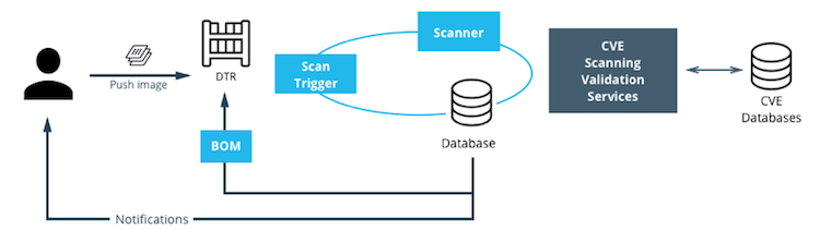
Setup Image Scanning
Before beginning, make sure the MSR license includes Docker Security Scanning and that the Docker ID being used can access and download this license from the Docker Store.
To enable Image Scanning, go to System -> Security, and select
Enable Scanning. Then select whether to use the Docker-supplied CVE
database (Online — the default option) or use a locally-uploaded
file (Offline — this option is only recommended for environments
that are isolated from the Internet or otherwise can’t connect to Docker
for consistent updates). Once enabled in online mode, MSR downloads the
CVE database from Docker, which may take a while for the initial sync.
If the installation cannot access
https://dss-cve-updates.docker.com/ manually upload a .tar file
containing the security database.
- If using Online mode, the MSR instance contacts a Docker server, download the latest vulnerability database, and install it. Scanning can begin once this process completes.
- If using Offline mode, use the instructions in Update scanning database - offline mode to upload an initial security database.

By default, when Security Scanning is enabled, new repositories
automatically scan on docker push, but any repositories that existed
before scanning was enabled are set to “scan manually” mode by default.
If these repositories are still in use, this setting can be changed from
each repository’s System page.
CVE Offline Database
If the MSR instance cannot contact the update server, download and
install a .tar file that contains the database updates. These
offline CVE database files can be retrieved from
Store.docker.com under My Content
License Setup.
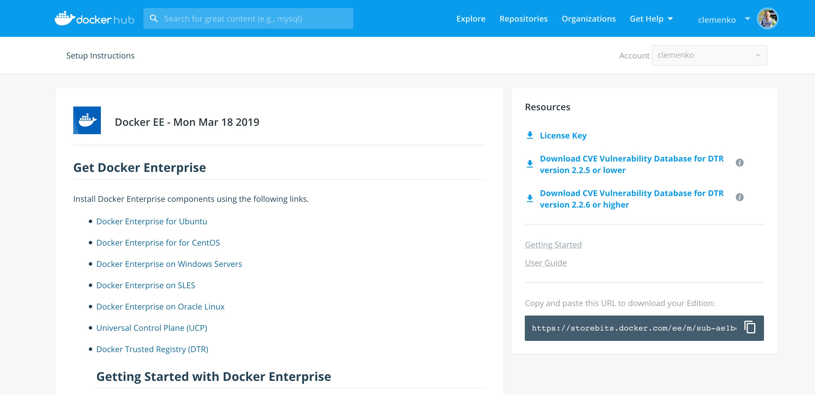
Scanning Results
To see the results of the scans, navigate to the repository itself, then click Images. A clean image scan has a green checkmark shield icon:
Vulnerabilities will be listed in terms of Critical, Major, and Minor. Click View details to see more. There are two views for the scanning results, Layers and Components. The Layers view shows which layer of the image had the vulnerable binary. This is extremely useful when diagnosing where the vulnerability is in the Dockerfile:

The vulnerable binary is displayed, along with all the other contents of the layer, when the layer itself is clicked on.
From the Components view, the CVE number, a link to CVE database, file path, layers affected, severity, and description of severity are available:

Now it is possible to take action against and vulnerable binary/layer/image with the CVE’s listed. Clicking the CVE itself will take you to Mitre’s CVE site.
If vulnerable components are discovered, check if there is an updated version available where the security vulnerability has been addressed. If necessary, contact the component’s maintainers to ensure that the vulnerability is being addressed in a future version or patch update.
If the vulnerability is in a base layer (such as an operating
system) it might not be possible to correct the issue in the image. In
this case, switching to a different version of the base layer or finding
an equivalent, less vulnerable base layer might help. Deciding that the
vulnerability or exposure is acceptable is also an option.
Address vulnerabilities in the repositories by updating the images to use updated and corrected versions of vulnerable components, or by using different components that provide the same functionality. After updating the source code, run a build to create a new image, tag the image, and push the updated image to the MSR instance. Then re-scan the image to confirm that the vulnerabilities have been addressed.
What happens when there are new vulnerabilities released? There are actually two phases. The first phase is to fingerprint the image’s binaries and layers into hashes. The second phase is to compare the hashes with the CVE database. The fingerprinting phase takes the longest amount of time to complete. Comparing the hashes is very quick. When there is a new CVE database, MSR simply compares the existing hashes with the new database. This process is also very quick. The scan results are always updated.
Webhooks
Webhooks can be managed through the GUI. MSR includes webhooks for common events, such as pushing a new tag or deleting an image. This allows you to build complex CI and CD pipelines from your own MSR cluster.
The webhook events you can subscribe to are as follows (specific to a repository):
- Tag push
- Tag delete
- Manifest push
- Manifest delete
- Security scan completed
To subscribe to an event requires admin access to the particular repository. A global administrator can subscribe to any event. For example, a user must be an admin of repository to subscribe to its tag push events.
More information about webhooks can be found in the Docker docs. MSR also presents the API by going to the menu under the login in the upper right, and then clicking API docs.

Image Immutability
MSR provides an option to set a repository to Immutable. Setting a repository to Immutable means the tags can not be overwritten. This is a great feature for ensure the base images do not change over time. This next example is of the Alpine base image. Ideally CI would update the base image and push to MSR with a specific tag. Being Immutable simply guarantees that an authorized user can always go back to the specific tag and trust it has not changed. An Image Promotion Policy can extend on this.

Image Promotion Policy
The release of Docker Trusted Registry 2.3.0 added a new way to promote images. Policies can be created for promotion based upon thresholds for vulnerabilities, tag matching, and package names, and even the license. This gives great powers in automating the flow of images. It also ensures that images that don’t match the policy don’t make it to production. The criteria are as follows:
- Tag Name
- Package Name
- All Vulnerabilities
- Critical Vulnerabilities
- Major Vulnerabilities
- Minor Vulnerabilities
- All Licenses

Policies can be created and viewed from either the source or the target.
Consider the example of All Vulnerabilities to setup a promotion
policy for the admin/alpine_build repo to “promote” to
admin/alpine if there are zero vulnerabilities. Navigate to the
source repository and go to the Policies tab. From there select
New Promotion Policy. Select the All Vulnerabilities on the
left. Then click less than or equals and enter 0 (zero) into the
textbox,and click Add. Select a target for the promotion. On the
right hand side select the namespace and image to be the target. Now
click Save & Apply. Applying the policy will execute against the
source repository. Save will apply the policy to future pushes.
Notice the Tag Name In Target that allows changes to the tag according to some variables. It is recommended to start with leaving the tag name the same. For more information please check out the Image Promotion Policy docs.

Notice the PROMOTED badge. One thing to note is that the Notary signature is not promoted with the image. This means a CI system will be needed to sign the promoted images. This can be achieved with the use of webhooks and promotion policy.

Imagine a MSR setup where the base images get pushed from Jenkins to MSR. Then the images get scanned and promoted if they have zero vulnerabilities. Sounds like a good part of a Secure Supply Chain.
Image Mirroring
MSR adds Image Mirroring, which allows for images to be mirrored between MSR and another MSR. It also allows for mirroring between MSR and hub.docker.com. Image Mirroring allows from increased control of your image pipeline.

One of the new features of Image Mirroring is the ability to PULL images from hub.docker.com. Another great feature is the ability to trigger the PUSH mirroring to another MSR based on security scans or other criteria. Image Mirroring even has the capability to change the tag name. This is a good way to tag the image that it was pushed.

Defense Information Systems Agency Security Technical Implementation Guides
When building a Secure By Default platform one needs to consider the verification and Governmental use. Thanks to Defense Information Systems Agency ( DISA ) for allowing Docker to become the first Docker Container platform with a Security Technical Implementation Guides ( STIG ). Having a STIG allows Agencies to ensure they are running Docker Enterprise is the most secure manor. STIGs are formatted in xml and require viewing through the STIG viewer. DISA has a page dedicated to STIG Viewing tools. Specifically you can find the latest DISA STIG Viewer here.
The STIG can currently be found in the August 8th STIG Compliation. Once unziped navigate to OS-VRT- Docker Enterprise 2.x STIG and locate U_Docker_Enterprise_2-x_Linux-UNIX_V1R1_STIG.zip. Contained in final zip file is all the documentation and xml STIG itself. Here are quick links to the STIG.
Quick Access to STIG
U_Docker_Enterprise_2-x_Linux-UNIX_V1R1_Overview.pdfU_Docker_Enterprise_2-x_Linux-UNIX_V1R1_STIG.zipunclass-STIGViewer_2-9.zip- unclass-STIGViewer_2-9.zip
- DISA STIG Tools
Please keep in mind that the current STIG calls out Docker Enterprise 2.x. The STIG absolutely applies to Docker Enterprise 3.X!
STIG Overview
There is some good information about the STIG and DISA’s authority from
Overview PDF. Here
are two highlights.
1.1 Executive Summary This Docker Enterprise 2.x Linux/UNIX Security Technical Implementation Guide (STIG) provides the technical security policies, requirements, and implementation details for applying security concepts to container platforms that are built using the Docker Enterprise product suite, specifically for Linux and UNIX, which is built and maintained by Docker, Inc. It also incorporates high-level technical guidance for establishing a secure software supply chain, using the Docker Enterprise platform in concert with containers based on a standard image format and runtime prevalent in industry. The Docker platform is designed to give both developers and IT professionals the freedom to build, manage, and secure mission-critical applications with no technology or infrastructure lock-in. Docker enables a secure, trusted software supply chain workflow which is used as the foundation for building software and for deploying applications onto any infrastructure; from traditional on-premises datacenters, to public cloud providers.
1.2 Authority DoD Instruction (DoDI) 8500.01 requires that “all IT that receives, processes, stores, displays, or transmits DoD information will be […] configured […] consistent with applicable DoD cybersecurity policies, standards, and architectures” and tasks that Defense Information Systems Agency (DISA) “develops and maintains control correlation identifiers (CCIs), security requirements guides (SRGs), security technical implementation guides (STIGs), and mobile code risk categories and usage guides that implement and are consistent with DoD cybersecurity policies, standards, architectures, security controls, and validation procedures, with the support of the NSA/CSS, using input from stakeholders, and using automation whenever possible.” This document is provided under the authority of DoDI 8500.01. Although the use of the principles and guidelines in these SRGs/STIGs provides an environment that contributes to the security requirements of DoD systems, applicable NIST SP 800-53 cybersecurity controls need to be applied to all systems and architectures based on the Committee on National Security Systems (CNSS) Instruction (CNSSI) 1253.
1.3 Vulnerability Severity Category Code Definitions Severity Category Codes (referred to as CAT) are a measure of vulnerabilities used to assess a facility or system security posture. Each security policy specified in this document is assigned a Severity Category Code of CAT I, II, or III.
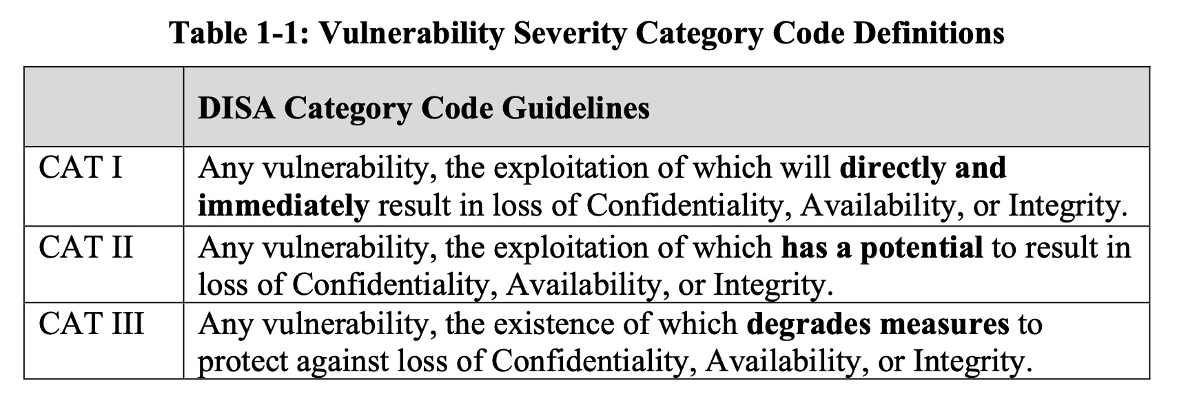
Based on DISA’a categories we are going to look at CAT I controls. For those keeping score here are the break down of controls.
| Category | Controls |
|---|---|
| CAT 1 | 23 |
| CAT 2 | 72 |
| CAT 3 | 5 |
| Total | 100 |
CAT 1 Controls
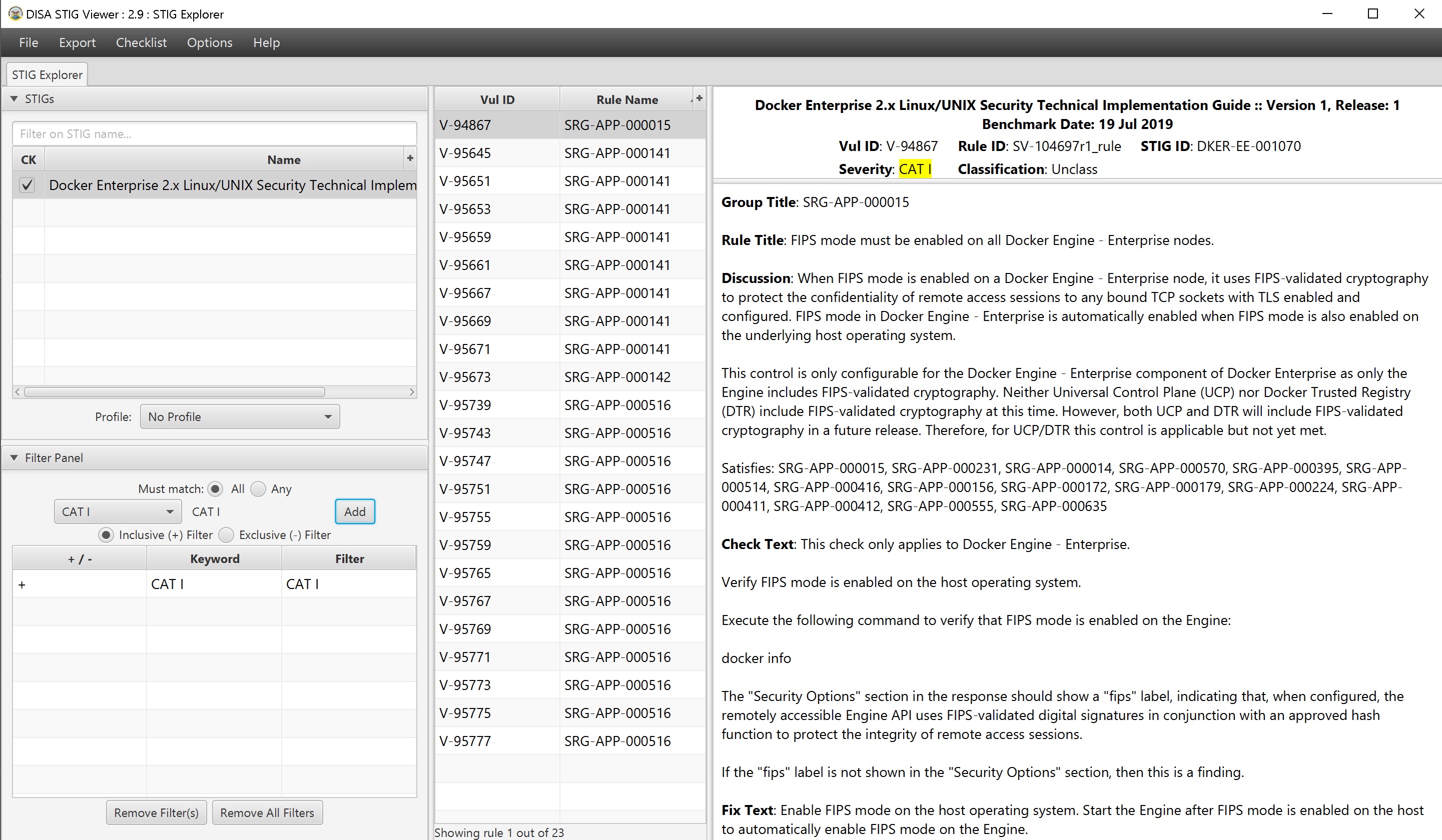
Cat 1 Controls and the fixes are listed below. This is a brief summary of the controls and fixes. PLEASE read the STIG itself for more context.
| Control ID | Group Title | Rule Title | Fix |
|---|---|---|---|
| V-94867 | SRG-APP-000015 | FIPS mode must be enabled on all Mirantis Container Runtime nodes. | Enable FIPS mode |
| V-95645 | SRG-APP-000141 | Docker Enterprise hosts network namespace must not be shared. | Do not pass --net=host or --network=host options when starting
the container. |
| V-95651 | SRG-APP-000141 | All Docker Enterprise containers root filesystem must be mounted as read only. | Add a --read-only flag at a container’s runtime to enforce the
container’s root filesystem to be mounted as read only. |
| V-95653 | SRG-APP-000141 | Docker Enterprise host devices must not be directly exposed to containers. | Do not directly expose the host devices to containers. There are exceptions. |
| V-95659 | SRG-APP-000141 | The Docker Enterprise default seccomp profile must not be disabled. | Ensure the default seccomp profile is not disabled. |
| V-95661 | SRG-APP-000141 | Docker Enterprise exec commands must not be used with privileged option. | Do not use --privileged option in docker exec command. |
| V-95667 | SRG-APP-000141 | All Docker Enterprise containers must be restricted from acquiring additional privileges. | Start containers with --security-opt=no-new-privileges. |
| V-95669 | SRG-APP-000141 | The Docker Enterprise hosts user namespace must not be shared. | Do not share user namespaces between host and containers. |
| V-95671 | SRG-APP-000141 | The Docker Enterprise socket must not be mounted inside any containers. | When using the -v/--volume flags to mount volumes to containers in a
docker run command, do not use docker.sock as a volume. |
| V-95673 | SRG-APP-000142 | Docker Enterprise privileged ports must not be mapped within containers. | Do not map the container ports to privileged host ports when starting a container. |
| V-95739 | SRG-APP-000516 | Docker Enterprise docker.service file ownership must be set to
root:root. |
Ensure chown root:root /usr/lib/systemd/system/docker.service. |
| V-95743 | SRG-APP-000516 | Docker Enterprise docker.socket file ownership must be set to
root:root. |
Ensure chown root:root /usr/lib/systemd/system/docker.socket. |
| V-95747 | SRG-APP-000516 | Docker Enterprise /etc/docker directory ownership must be set to
root:root. |
Ensure chown root:root /etc/docker. |
| V-95751 | SRG-APP-000516 | Docker Enterprise registry certificate file ownership must be set to
root:root. |
Ensure chown root:root /etc/docker/certs.d/<registry-name>/*. |
| V-95755 | SRG-APP-000516 | Docker Enterprise TLS certificate authority (CA) certificate file
ownership must be set to root:root. |
Ensure chown -R root:root
/var/lib/docker/volumes/ucp-client-root-ca/;
chown -R root:root /var/lib/docker/volumes/ucp-cluster-root-ca/. |
| V-95759 | SRG-APP-000516 | Docker Enterprise server certificate file ownership must be set to
nobody:nobody (99:99) |
Ensure chown 99:99
/var/lib/docker/volumes/ucp-controller-client-certs/_data/*;
chown 99:99 /var/lib/docker/volumes/ucp-controller-server-certs/_data/*. |
| V-95765 | SRG-APP-000516 | Docker Enterprise server certificate key file permissions must be set to 400. | Ensure chmod 400
/var/lib/docker/volumes/ucp-controller-client-certs/_data/key.pem;
chmod 400 /var/lib/docker/volumes/ucp-controller-server-certs/_data/key.pem. |
| V-95767 | SRG-APP-000516 | Docker Enterprise socket file ownership must be set to root:docker. | Ensure chown root:docker /var/run/docker.sock. |
| V-95769 | SRG-APP-000516 | Docker Enterprise socket file permissions must be set to 660 or more restrictive. | Ensure chmod 660 /var/run/docker.sock. |
| V-95771 | SRG-APP-000516 | Docker Enterprise daemon.json file ownership must be set to
root:root. |
Ensure chown root:root /etc/docker/daemon.json. |
| V-95773 | SRG-APP-000516 | Docker Enterprise daemon.json file permissions must be set to 644 or more restrictive. | Ensure chmod 644 /etc/docker/daemon.json. |
| V-95775 | SRG-APP-000516 | Docker Enterprise /etc/default/docker file ownership must be set to
root:root. |
Ensure chown root:root /etc/default/docker. |
| V-95777 | SRG-APP-000516 | Docker Enterprise /etc/default/docker file permissions must be set to 644 or more restrictive. | Ensure chmod 644 /etc/default/docker. |
Please take note that some of the CAT 1 Controls are around what NOT to do. And the other controls are around ensuring the default install has not changed. Basically most of the controls can me mitigated by limiting access to the node, aka NO SSH ACCESS!
CAT 2 Controls - Stand Outs
| Control ID | Group Title | Rule Title | Fix |
|---|---|---|---|
| V-94869 | SRG-APP-000016 | The audit log configuration level must be set to request in the Mirantis Kubernetes Engine (MKE) component of Docker Enterprise. | As a Docker Enterprise Admin, navigate to “Admin Settings” |
| V-95113 | SRG-APP-000023 | LDAP integration in Docker Enterprise must be configured. | Enable LDAP |
| V-95355 | SRG-APP-000033 | Use RBAC | Use RBAC |
| V-95615 | SRG-APP-000141 | The userland proxy capability in the Mirantis Container Runtime component of Docker Enterprise must be disabled. | DO NOT Implement. This will break MKE. |
STIG Summary
There are a lot of controls within the STIG. Please read and pay close attention.
Summary
If you are reading this then contragulations. This reference architecture is not an easy read. Hopefuly as documented Docker Enterprise is Secure by Default. Especially with the inclusion of Kube Hunter and the DISA STIG.
Security is not what happens to you, but something you are involved in.
Building a Docker Secure Supply Chain
Introduction
Creating a Secure Supply Chain of images is vitally important. Every organization needs to weigh ALL options available and understand the security risks. Having so many options for images makes it difficult to pick the right ones. Ultimately every organization needs to know the provenance of all the images, even when trusting an upstream image from hub.docker.com. Once the images are imported into the infrastructure, a vulnerability scan is vital. Mirantis Secure Registry with Image Scanning gives insight into any vulnerabilities. Finally, everything needs to be automated to provide a succinct audit trail.
What You Will Learn
This reference architecture describes the components that make up a Secure Supply Chain. Topics include using Git, GitLab, and the Docker Hub to feed the supply chain. All the tools listed and demonstrated within this reference architecture can be replaced with alternatives. The Secure Supply Chain can be broken into three stages:
- Stage 1 is a code repository.
- Stage 2 is Continuous Integration.
- Stage 3 is a registry that can scan images.
Even though there are many alternatives, this document focuses on one set:
- GitLab (Code Stage 1)
- GitLab Runner (Build Automation Stage 2)
- Mirantis Secure Registry (Scanning and Promotion Stage 3)
One motto to remember for this reference architecture is “No human will build or deploy code headed to production!”
Prerequisites
Before continuing, become familiar with and understand:
Abbreviations
The following abbreviations are used in this document:
| Abbreviation | Description |
|---|---|
| MKE | Mirantis Kubernetes Engine |
| MSR | Mirantis Secure Registry |
| DCT | Docker Content Trust |
| RBAC | Role Based Access Controls |
| CA | Certificate Authority |
| CI | Continuous Integration |
| CD | Continuous Deployment |
| HA | High Availability |
| BOM | Bill of Materials |
| CLI | Command Line Interface |
Why
There are several good reasons why you need a Secure Supply Chain. Creating a Secure Supply Chain is theoretically mandatory for production. Non-production pipelines can also take advantage of having an automated base image. When thinking about Supply Chain, a couple of key phrases come to mind:
- “No human will build or deploy code headed to production!”
- It helps prevent malicious code from being snuck into approved code. It also helps prevent insider threat.
- “Everything needs an audit trail.”
- Being able to prove the what, when, why, and how questions makes everyone’s job easier.
- “Every supply chain needs a known good source.”
- Would you build a house in the middle of a swamp?
Ideally you want the shortest path for images. You want to guarantee the success of the image making it through the chain. Limiting the steps is a great way to reduce the number of moving parts. At a high level, only two components, Git (GitLab) and Mirantis Secure Registry (MSR), are necessary.
Below is a basic diagram of the path today.
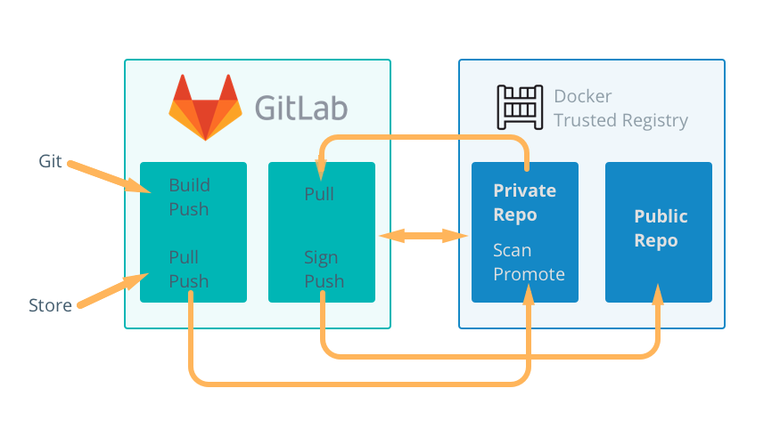
Known Good Source
No matter how good a supply chain is, it all depends on starting with a “Known Good Source”. Stage 1 can be broken down into two possible starting points.
- Automated, pre-built, verified, and preferably certified images from the Docker Hub
- A private, secure Git repository with Dockerfiles and other YAMLs
There are good reasons for both. The Docker Hub path means that the upstream image is inherited with a bit of risk in how the vendor built it. The Git path means there are risks taken when building the image. Both entry points have their pros and cons. Both starting points have verifiable contents to ensure they are a “known good source”.
The next sections look at both sources in more detail.
Docker Hub, The New Docker Hub
Docker Hub, hub.docker.com, should be the first place to look for images that are ready for use. The owners of the images carry the responsibility of updating and ensuring that there are no vulnerabilities. Thanks to Docker Hub, all Certified and Official images are scanned for vulnerabilities. Docker Hub and Vendors take things a step further with Certified images. Certified images go through an extensive vetting process, and essentially come with a guarantee from the vendor and Docker that the container will work. The Store also includes Official images. Official images, updated regularly, are built by Docker. Docker Hub also contain community images, which should be used at last resort.
Picking the Right Upstream
Picking the right images from Docker Hub is critical. Start with Certified Images, then move on to official images. Lastly, consider community images. Only use community images that are an automated build. This helps ensure that they are updated in a timely fashion. Verification of the freshness of the image is important as well.
From a blog post on Certified Images:
The Docker Certification Program is designed for both technology partners and enterprise customers to recognize Containers and Plugins that excel in quality, collaborative support, and compliance. Docker Certification is aligned to the available Docker EE infrastructure and gives enterprises a trusted way to run more technology in containers with support from both Docker and the publisher. Customers can quickly identify the Certified Containers and Plugins with visible badges and be confident that they were built with best practices, tested to operate smoothly on Docker EE.
When searching Docker Hub for images, make sure to check the Docker Certified checkbox.
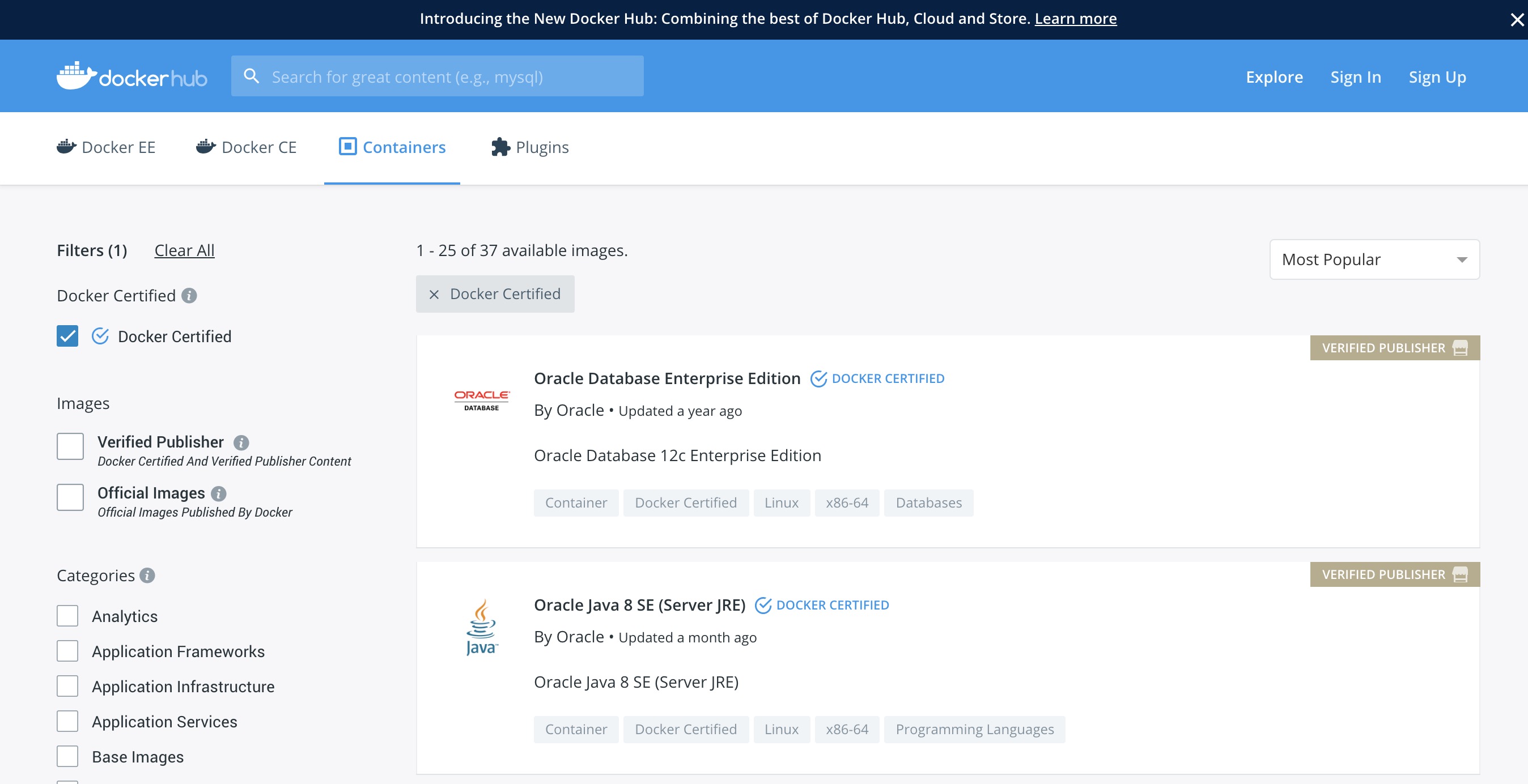
One of the great features about Docker Hub is that the images are scanned for security vulnerabilities. This allows for inspection of the images before pulling.
When using upstream images that are not Official or Certified, ensure that the image is an “automated build”. Reviewing the Dockerfile is an important step to ensure only the correct bits are in the image. Last resort is to consider creating an “automated” image for the community.
Please keep in mind that ANY image pulled from Hub or Store should also receive the same level of scrutiny through Mirantis Secure Registry.
Git - (GitLab CE)
In today’s modern enterprise, version control systems are the center of all code. Version control systems such as Git are also a great way to keep track of configuration, becoming the “Source of Truth” for your enterprise. There are several companies that produce Git servers. GitLab CE is a great open source one. In the following example, GitLab Community Edition is used.
The ideal Git repo structure contains all the files necessary for
building and deploying. Specifically the Dockerfile, any code, and
the stack.yml. The Dockerfile is the build recipe for the Docker
image. The stack.yml, also known as a compose YAML file, is used for
describing the stack.
Set Up GitLab
GitLab has some good instructions for setting up with Docker images. Because Git uses SSH port (22) by default, either the host’s port or Git’s port needs to be changed. The following shows how to move GitLab’s port to 2022. For production, moving the host’s SSH port might make more sense. Also, permanent storage is needed for a stateful install. Here is an example Docker Compose for setting up Gitlab-CE:
version: "3.3"
services:
  gitlab:
    image: gitlab/gitlab-ce:latest
    ports:
      - 80:80
      - 443:443
      - 2022:22
    volumes:
      - /var/run/docker.sock:/var/run/docker.sock
      - /srv/gitlab/config:/etc/gitlab
      - /srv/gitlab/logs:/var/log/gitlab
      - /srv/gitlab/data:/var/opt/gitlab
    restart: always
    environment:
      - GITLAB_OMNIBUS_CONFIG="external_url 'http://my.domain.com/'; gitlab_rails['lfs_enabled'] = true;"
    networks:
      gitlab:

  gitlab-runner:
    image: gitlab/gitlab-runner:alpine
    volumes:
      - /var/run/docker.sock:/var/run/docker.sock
      - /srv/gitlab-runner/config:/etc/gitlab-runner
      - /root/.docker:/root/.docker
      - /root/.notary:/root/.notary
    restart: always
    networks:
      gitlab:

networks:
  gitlab:
Save this as gitlab.yml. Then execute the following commands:
$ sudo docker swarm init
$ sudo docker stack deploy -c gitlab.yml gitlab
Note that it will take a minute for GitLab to start.
Continuous Integration Automation
In order to leverage the idea of “No human will push code to
production,” you need to automate all the things. Thanks to recent
editions of GitLab, you can configure CI/CD functions directly. This
greatly simplifies setup and maintainability. To take advantage of
CI/CD, first register at least one runner. The runner is included in the
gitlab.yml from the previous setup section. The next step is to
configure the runner.
Configure the Runner
To activate the runner installed with the docker stack deploy from
the previous section, you need to get the runner token. Navigate to
Admin Area –> Runners. Here you can find the token needed to
register the runner.
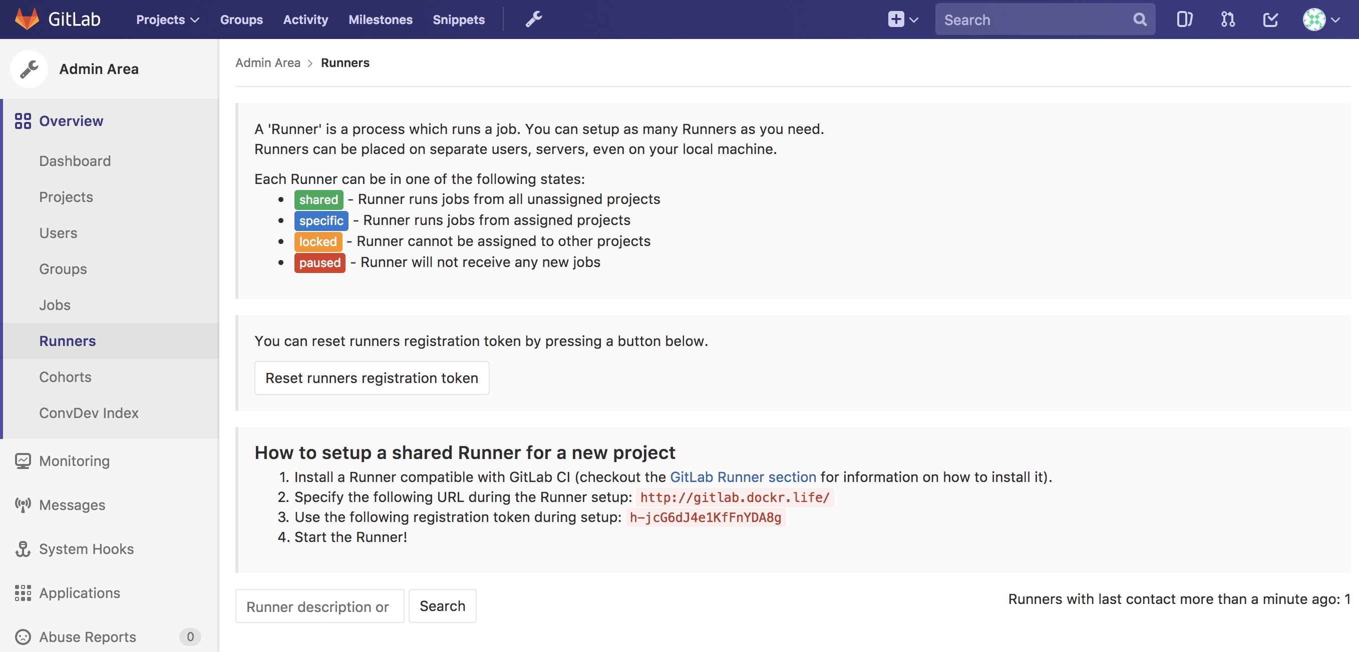
Luckily there is a shortcut to registering the runner. Simply ssh into the GitLab node and run the following Docker command (Notice the token from the GitLab CE page):
$ docker exec -it $(docker ps --format '{{.Names}}\t{{.ID}}'|grep runner|awk '{print $2}') \
    gitlab-runner \
    register -n \
    --url http://gitlab.example.com \
    --registration-token $token \
    --executor docker \
    --description "local docker" \
    --docker-image "docker:latest" \
    --docker-volumes "/var/run/docker.sock:/var/run/docker.sock" \
    --docker-volumes "/root/.docker:/root/.docker"
Once registered you should see the Runner available with a shared
tag. You also want to make sure that Run untagged jobs is checked
and that Lock to current projects is unchecked.
Repository Contents
One great way to leverage the “Source of Truth” is to store all the
contents that compose the image and the stack together. Simply create a
directory for each component in the root of the repository, then store
only the bits that make up that component in its appropriate directory.
In this example there is a three tier app made up of “web,”
“middleware,” and “db”. The stack.yml would also be stored at the
root level of the repository. Ideally, the directory structure would
contain:
- Directories for the components. Each directory would contain the
specific
Dockerfile. Source bits and artifacts for each component in a separate directory. - A
stack.yml, which is used fordocker stack deploy. - GitLab CI declarative,
.gitlab-ci.yml.
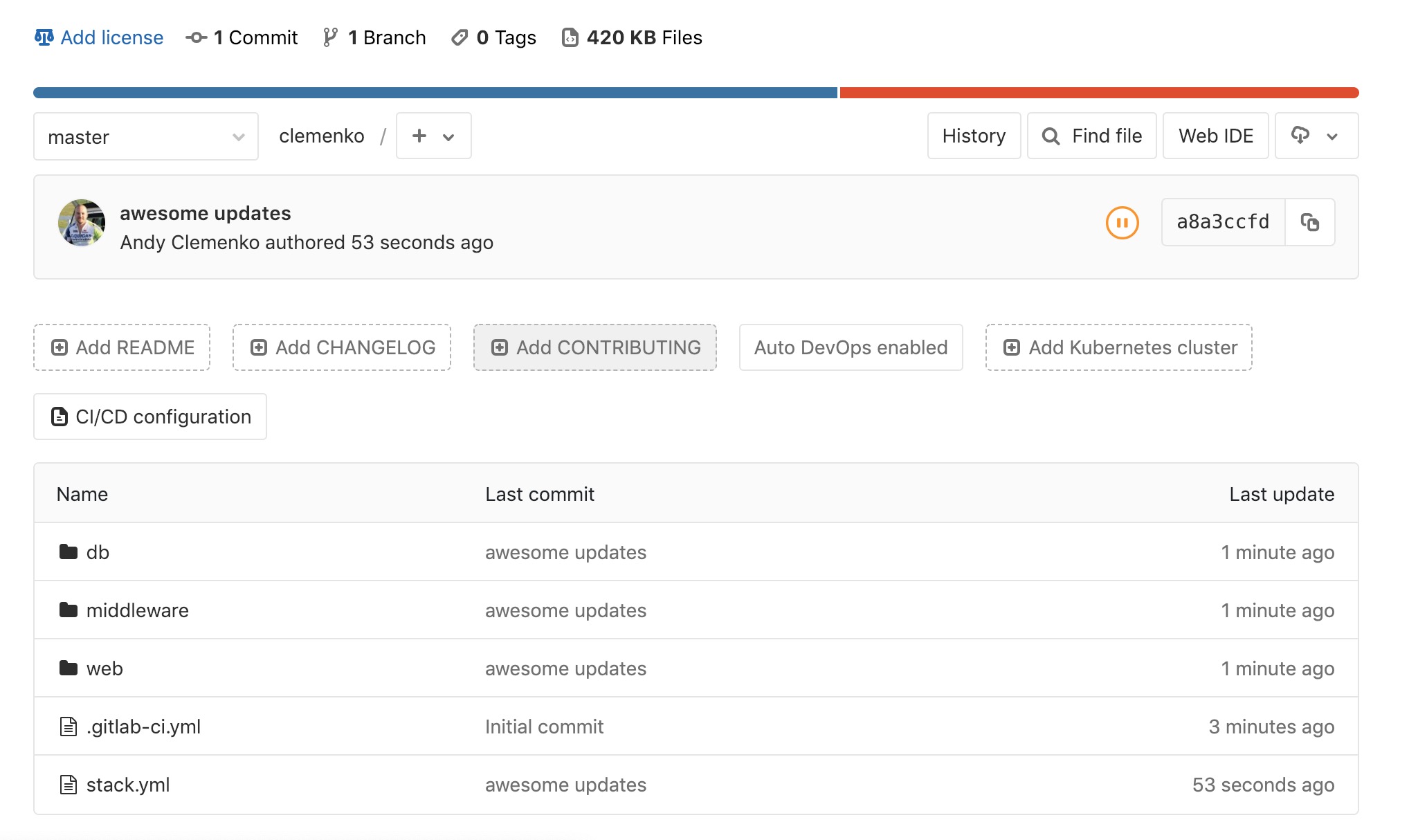
Don’t forget to utilize multi-stage builds in Dockerfiles. Multi-stage builds help to reduce the size of the resulting image. Please take a look at the multi-stage documentation.
Dockerfile Best Practices
It is worth looking at what makes a good Dockerfile. One thing that
is commonly overlooked is the use of labels. Since it is simply extra
metadata for the image itself it doen’t affect the run time at all. We
highly recommend adding labels from opencontainers
spec.
And the most important label of all is the
org.opencontainers.image.authors. This is a great resource for
tracking back who wrote the dockerfile. You can follow this Dockerfile
example:
FROM alpine

ARG BUILD_DATE
ARG BUILD_VERSION

LABEL org.opencontainers.image.authors="clemenko@docker.com" \
      org.opencontainers.image.source="https://github.com/clemenko/dockerfiles/tree/master/demo_flask" \
      org.opencontainers.image.created=$BUILD_DATE \
      org.opencontainers.image.title="clemenko/flask_demo" \
      org.opencontainers.image.description="The repository contains a simple flask application " \
      org.opencontainers.image.source=$BUILD_VERSION

RUN apk -U upgrade && apk add --no-cache curl py-pip  &&\
    pip install --no-cache-dir --upgrade pip &&\
    pip install --no-cache-dir flask redis pymongo &&\
    rm -rf /var/cache/apk/*

WORKDIR /code
ADD . /code
EXPOSE 5000
HEALTHCHECK CMD curl -f http://localhost:5000/healthz || exit 1
CMD ["python", "app.py"]
Build Declarative
Here is where the CI magic happens. GitLab looks to a file at the root
of the repository called .gitlab-ci.yml. This is the CI declarative
file.
Note
Check out the GitLab documentation on this topic.
Consider the following scenarios. Be sure to configure the variables in each individual repository.
Here is a good example of building an image from git itself.
# Official docker image.
variables:
  DOCKER_DRIVER: overlay2

image: docker:latest

before_script:
  - docker login -u $DTR_USERNAME -p $DTR_PASSWORD $DTR_SERVER

build:
  stage: build
  script:
    - docker build --pull -t dtr.example.com/admin/"$CI_PROJECT_NAME"_build:$CI_JOB_ID .
    - docker push dtr.example.com/admin/"$CI_PROJECT_NAME"_build:$CI_JOB_ID
    - docker rmi dtr.example.com/admin/"$CI_PROJECT_NAME"_build:$CI_JOB_ID
Here is a good example of a .gitlab-ci.yml for pulling, tagging, and
pushing an image from hub.docker.com to your MSR.
# Official docker image.
variables:
  DOCKER_DRIVER: overlay2

image: docker:latest

before_script:
  - docker login -u $DTR_USERNAME -p $DTR_PASSWORD $DTR_SERVER

stages:
  - signer

signer:
  stage: signer
  script:
    - docker pull $DTR_SERVER/admin/flask:latest
    - export DOCKER_CONTENT_TRUST=1
    - docker push $DTR_SERVER/admin/flask:latest
    - docker rmi $DTR_SERVER/admin/flask:latest
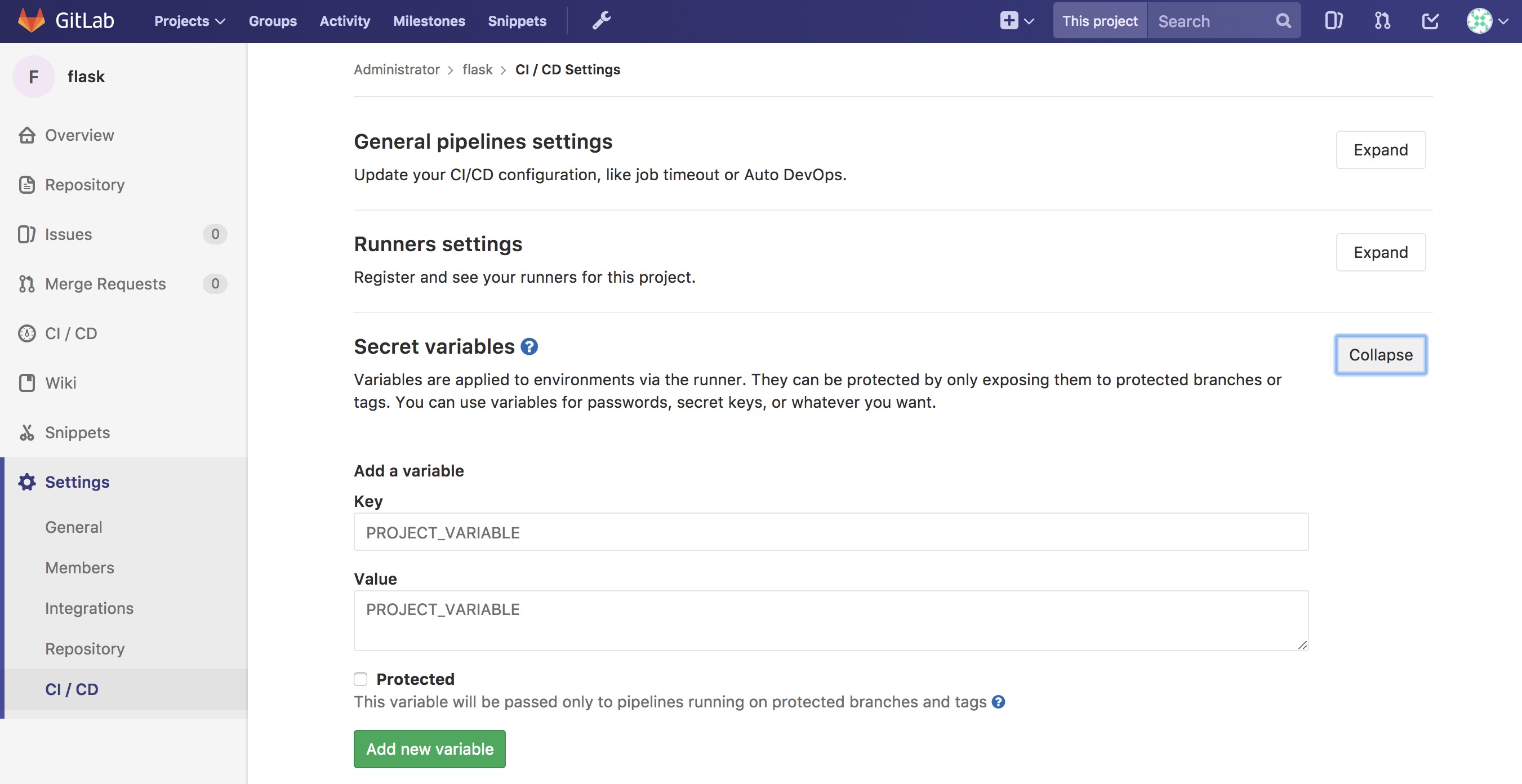
GitLab is now setup with variables and build declaratives. Next, add a trigger to your project.
Pipeline Triggers
GitLab includes an awesome CI tool as well as a way to trigger the pipeline remotely. GitLab calls these triggers. The easiest way to create these triggers is to navigate to Projects –> Settings –> CI/CD –> Pipeline triggers –> Expand.
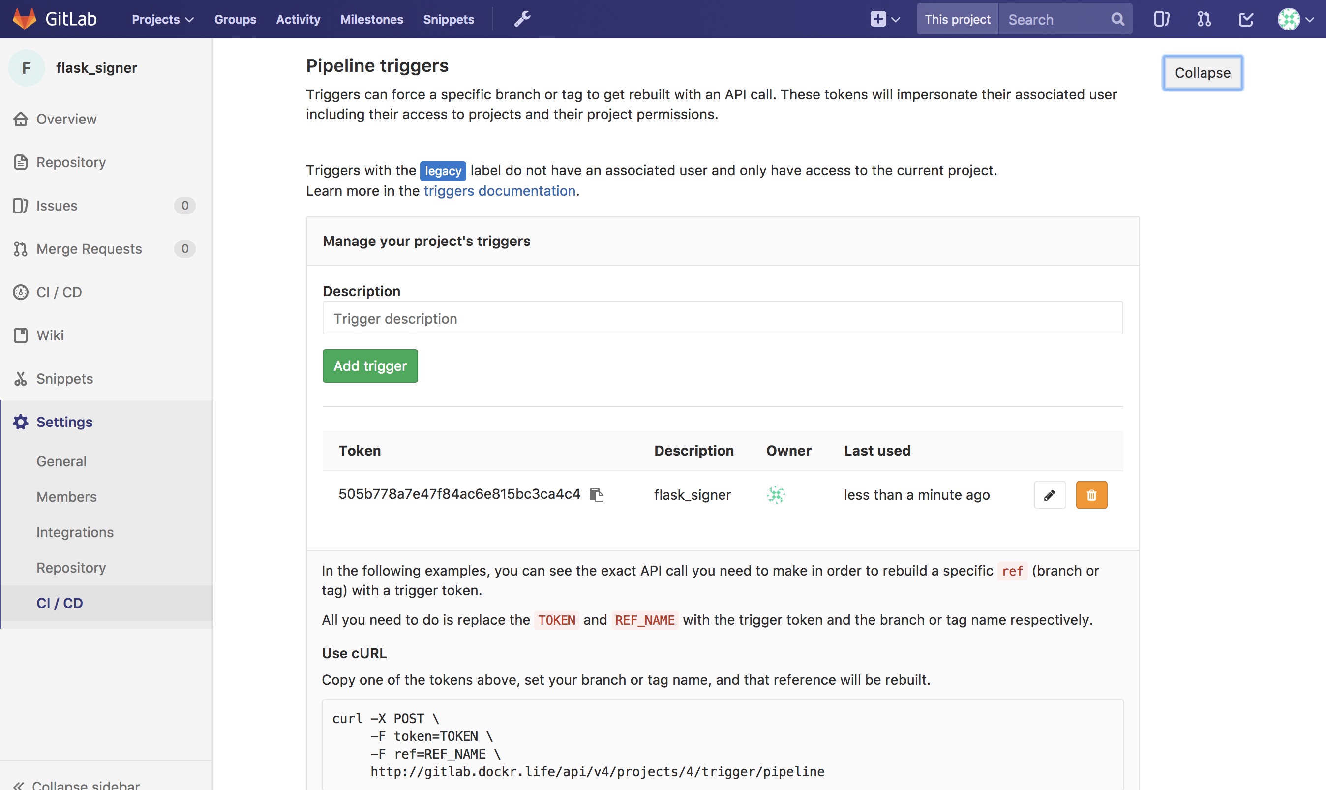
Here is an example of the trigger format.
http://gitlab.example.com/api/v4/projects/$PROJECT/trigger/pipeline?token=$TOKEN&ref=$REF.
The three fields that are needed here are $PROJECT, $TOKEN, and
$REF. $REF should be set to the branch name. $TOKEN should
be set to the token you get from GitLab. The best way to get the
$PROJECT is to simply copy the URL in the Pipeline Triggers
page. You will need the Pipeline Triggers later.
Next, add Mirantis Secure Registry (MSR).
Mirantis Secure Registry
MSR is much more than a simple registry. It includes some great features that increase the strength of the supply chain. Some of the new features include image promotion and immutability.
The following sections look at some of these new features.
Image Scanning
MSR includes on-site image scanning. The on-site scanning engine within MSR scans images against the CVE Database. First, the scanner performs a binary scan on each layer of the image, identifies the software components in each layer, and indexes the SHA of each component. This binary scan evaluates the components on a bit-by-bit basis, so vulnerable components are discovered regardless of filename, whether or not they’re included on a distribution manifest or in a package manager, whether they are statically or dynamically linked, or even if they are from the base image OS distribution.
The scan then compares the SHA of each component against the CVE database (a “dictionary” of known information security vulnerabilities). When the CVE database is updated, the scanning service reviews the indexed components for any that match newly discovered vulnerabilities. Most scans complete within a few minutes; larger repositories may take longer to scan depending on your system resources. The scanning engine gives you a central point to scan all the images and delivers a Bill of Materials (BOM), which can be coupled with Notary to ensure an extremely secure supply chain for your images.
The scanning engine can also scan Windows binaries.
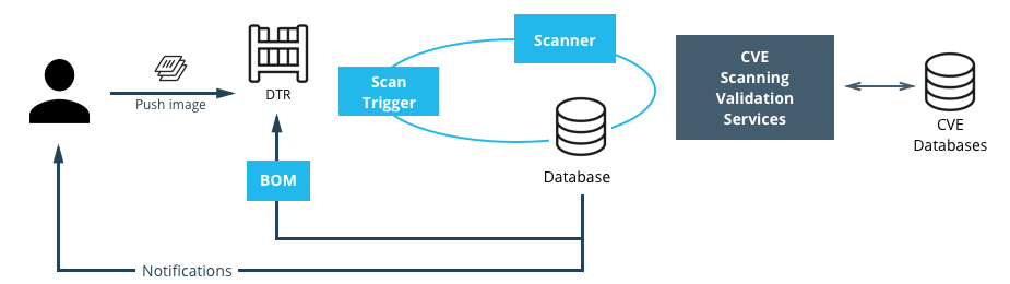
Set Up Image Scanning
Before you begin, make sure that you or your organization has purchased a MSR license that includes Docker Security Scanning and that your Docker ID can access and download this license from the Docker Hub.
By default, when Security Scanning is enabled, new repositories
automatically scan on docker push, but any repositories that existed
before scanning was enabled are set to “scan manually” mode by default.
If these repositories are still in use, you can change this setting from
each repository’s Settings page.
To enable Image Scanning, go to Settings –> Security, select Enable Scanning, and then select whether to use the Docker-supplied CVE database (Online — the default option) or use a locally-uploaded file (Offline — this option is only recommended for environments that are isolated from the Internet or otherwise can’t connect to Docker for consistent updates).
Once enabled in online mode, MSR downloads the CVE database from Docker,
which may take a while for the initial sync. If your installation cannot
access https://dss-cve-updates.docker.com/ you must manually upload
a .tar file containing the security database.
- If you are using Online mode, the MSR instance contacts a Docker server, downloads the latest vulnerability database, and installs it. Scanning can begin once this process completes.
- If you are using Offline mode, use the instructions in Update scanning database - offline mode to upload an initial security database.

CVE Offline Database
If your MSR instance cannot contact the update server, you can download
and install a .tar file that contains the database updates. These
offline CVE database files can be retrieved from
hub.docker.com under My Content –>
License Setup once you have logged in.
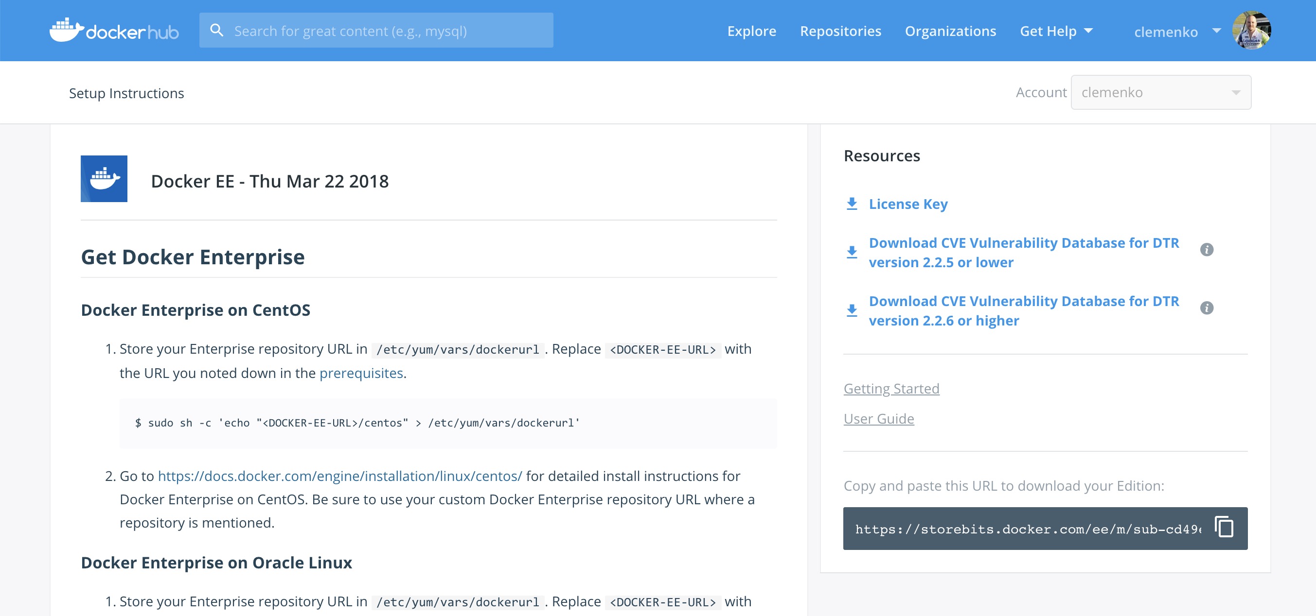
Scanning Results
To see the results of the scans, navigate to the repository itself, then click Images. A clean image scan has a green checkmark shield icon:

A vulnerable image scan will list the number of Critical, Major, and Minor vulnerabilities:

There are two views for the scanning results, Layers and Components. The Layers view shows which layer of the image had the vulnerable binary. This is extremely useful when diagnosing where the vulnerability is in the Dockerfile:

The vulnerable binary is displayed, along with all the other contents of the layer, when you click the layer itself. In this example there are a few potentially vulnerable binaries:
Click Components view. From the Component view the CVE number, a link to CVE database, file path, layers affected, severity, and description of severity are available:

Now you can take action against a vulnerable binary/layer/image.
If you discover vulnerable components, check if there is an updated version available where the security vulnerability has been addressed. If necessary, contact the component’s maintainers to ensure that the vulnerability is being addressed in a future version or patch update.
If the vulnerability is in a base layer (such as an operating
system) you might not be able to correct the issue in the image. In this
case, you might need to switch to a different version of the base layer,
or you might find an equivalent, less vulnerable base layer. You might
also decide that the vulnerability or exposure is acceptable.
Address vulnerabilities in your repositories by using updated and corrected versions of vulnerable components or by using different components that provide the same functionality. When you have updated the source code, run a build to create a new image, tag the image, and push the updated image to your MSR instance. You can then re-scan the image to confirm that you have addressed the vulnerabilities.
What happens when there are new vulnerabilities released? There are actually two phases. The first phase is to fingerprint the image’s binaries and layers into hashes. The second phase is to compare the hashes with the CVE database. The fingerprinting phase takes the longest amount of time to complete. Comparing the hashes is very quick. When there is a new CVE database, MSR simply compares the existing hashes with the new database. This process is also very quick. The scan results are always updated.
Now that you have scan results, it is time to add a Promotion Policy.
Image Promotion Policy
Since the release of Docker Trusted Registry 2.3.0 there are various ways to promote images based on promotion policies. You can create policies for promotion based upon thresholds for vulnerabilities, tag matching, and package names, and even the license. This gives great powers in automating the flow of images. It also ensures that images that don’t match the policy don’t make it to production. The criteria are as follows:
- Tag Name
- Package Name
- All Vulnerabilities
- Critical Vulnerabilities
- Major Vulnerabilities
- Minor Vulnerabilities
- All Licenses

You can create and view the policies from either the source or the
target. The following is an example of All Vulnerabilities. It sets
up a promotion policy for the admin/flask_build repo to “promote” to
admin/flask if there are zero vulnerabilities.
First, navigate to the source repository, and go to the Policies
tab. From there select New Promotion Policy. Select the All
Vulnerabilities on the left. Then click less than or equals, enter
0 (zero) into the textbox, and click Add. Now select a target
for the promotion. On the right hand side, select the namespace and
image to be the target. Click Save & Apply. Applying the policy
executes against the source repository. Save applies the policy to
future pushes.
Notice the Tag Name In Target. This option provides the ability to change the tag according to some variables. It is recommended that you start out leaving the tag name the same. For more information please check out the Image Promotion Policy docs.

Notice the PROMOTED badge. One thing to note is that the Notary signature is not promoted with the image. This means a CI system must sign the promoted images. This can be achieved with the use of webhooks and promotion policy.

Consider a MSR setup where the base images get pushed from Gitlab to MSR. Then the images get scanned and promoted if they have zero vulnerabilities — part of a good Secure Supply Chain. This leads to Image Immutability.
Image Immutability
MSR has the option to set a repository to Immutable. Setting a repository to Immutable means the tags can not be overwritten. This is a great feature for ensuring that your base images do not change over time. This example is of the Alpine base image. Ideally CI would update the base image and push to MSR with a specific tag. Being Immutable simply guarantees that you can always go back to the specific tag and trust it has not changed. This can be extended with an Image Promotion Policy.

Image Immutability + Promotion Policy
A great example of using the Promotion Policy with Immutable tags is
when you are building images directly from Git. This example uses a
simple flask app. The .gitlab-ci.yml has three basic steps : build,
push, remove. Push to a MSR repository,
dtr.example.com/admin/flask_build, where Immutability is turned on,
into a private repository.

GitLab pushes with the build number as the tag. The format looks like :
dtr.example.com/admin/flask_build:66. Since Immutability is turned
on, the tag of 66 can never be overwritten. This gives a solid
foundation. Next add two promotion policies based on the same
thresholds. The policy promotes the image to a public repo
dtr.example.com/admin/flask with the same tag.

The next link in the chain is to have webhooks.
Webhooks
Webhooks can be managed through the GUI. MSR includes webhooks for common events such as pushing a new tag or deleting an image. This allows you to build complex CI and CD pipelines from your own MSR cluster. The webhook events you can subscribe to are as follows (repository specific):
- Tag push
- Tag delete
- Manifest push
- Manifest delete
- Security scan completed
- Security scan failed
- Image promoted from repository
Webhooks are created on a per-repository basis. More information about webhooks can be found in the Docker docs. MSR also has an API link in the lower left of the every screen. Simply click API.
This example is a continuation of the previous example that uses the
dtr.example.com/admin/flask_build repository. Now, add a webhook. To
add one using the “Image promoted from repository” event, the webhook
must be configured to tell GitLab to use Notary and sign the image.

For reference the WEBHOOK URL we used
ishttp://gitlab.example.com/api/v4/projects/$PROJECT/trigger/pipeline?token=$TOKEN&ref=$REF.
The three fields that are needed here are $PROJECT, $TOKEN, and $REF.
$REF should be set to the branch name. $TOKEN should be set to the token
you get from GitLab. $PROJECT can be obtained from the trigger creation
page. More details about triggers can be found in the
Triggers section. The great thing about the
webhooks and triggers is they can kick off new jobs, similar to image
signing.
Content Trust/Image Signing — Notary
Notary is a tool for publishing and managing trusted collections of content. Publishers can digitally sign collection, and consumers can verify integrity and origin of content. This ability is built on a straightforward key management and signing interface to create signed collections and configure trusted publishers.
Docker Content Trust/Notary provides a cryptographic signature for each image. The signature provides security so that the image you want is the image you get. If you are curious about what makes Notary secure, read about Notary’s Architecture. Since Docker EE is “Secure by Default,” MSR comes with the Notary server out of the box.
A successfully signed image has a green check mark in the MSR GUI.

Signing with GitLab
When teams get large it becomes harder to manage all the developer keys. One method for reducing the management load is to not let developers sign images. Using GitLab to sign all the images that are destined for production eliminates most of the key management. The keys on the GitLab server still need to be protected and backed up.
The first step is to create a user account for your CI system. For
example, assume GitLab is the CI system. Navigate to MSR’s web
interface. As an admin user, navigate to Organizations, and select
New organization. Call this new organization ci. Next create a
team within the ci organization by clicking the Team + button.
Call the new team gitlab. Now add the GitLab user by navigating into
the team, and selecting Add User. Create a user with the name
gitlab, and set a strong password. This creates a new user and adds
them to the ci organization.

Now that the team is set up, turn on policy enforcement. Navigate to Admin Settings, and select the Docker Content Trust subsection. Select Run Only Signed Images to enable Docker Content Trust. Click Add Team + in blue to get to the next section. In Select Org… select the ci team that was just created. Next in the Select Team… box select gitlab. Save the settings.
This policy requires every image that is referenced in a
docker pull, docker run, or docker service create to be
signed by a key corresponding to a member of the gitlab team. In
this case, the only member is the gitlab user.

The signing policy implementation uses the certificates issued in user
client bundles to connect a signature to a user. Using an incognito
browser window (or otherwise), log into the gitlab user account you
created earlier. Download a client bundle for this user. It is also
recommended that you change the description associated with the public
key stored in MKE such that you can identify in the future which key is
being used for signing.
Please note each time a user retrieves a new client bundle, a new keypair is generated. It is therefore necessary to keep track of a specific bundle that a user chooses to designate as the user’s signing bundle.
Once you have decompressed the client bundle, the only two files you
need for the purposes of signing are cert.pem and key.pem. These
represent the public and private parts of the user’s signing identity
respectively. Load the key.pem file onto the GitLab servers, and use
cert.pem to create delegations for the gitlab user in our
Trusted Collection.
One thing to note is that you can now enforce signature policy on a single engine. You can find documentation for Enabling DCT in Mirantis Container Runtime Configuration
On the GitLab server, each repository will need to be initialized. On
the gitlab server, do the following:
# become root
$ sudo -i

# add DTR's CA to the HOST OS - Centos/Rhel
$ curl -sk https://dtr.example.com/ca -o /etc/pki/ca-trust/source/anchors/dtr.example.com.crt
$ update-ca-trust
$ systemctl restart docker

# set repository signing passwords
$ export DOCKER_CONTENT_TRUST_ROOT_PASSPHRASE="Pa22word" \
    DOCKER_CONTENT_TRUST_REPOSITORY_PASSPHRASE="Pa22word"

# add signer to repo
$ docker trust signer add --key cert.pem admin dtr.example.com/admin/flask

# add private key for signing
$ docker trust key load --name admin key.pem
To enable automated signing, the variable
DOCKER_CONTENT_TRUST_REPOSITORY_PASSPHRASE needs to be configured
within the GitLab project similarly to the Build Declarative variables.
Next, create the GitLab project for signing. Create a new project with
the following .gitlab-ci.yml. This uses the local
/root/.docker/trust directory.
# Official docker image.
variables:
  DOCKER_DRIVER: overlay2

image: docker:latest

before_script:
  - docker login -u $DTR_USERNAME -p $DTR_PASSWORD $DTR_SERVER

stages:
  - signer

signer:
  stage: signer
  script:
    - docker pull $DTR_SERVER/admin/flask:latest
    - docker trust sign $DTR_SERVER/admin/flask:latest
    - docker rmi $DTR_SERVER/admin/flask:latest
Here is what a successful output from the signing project should look like:
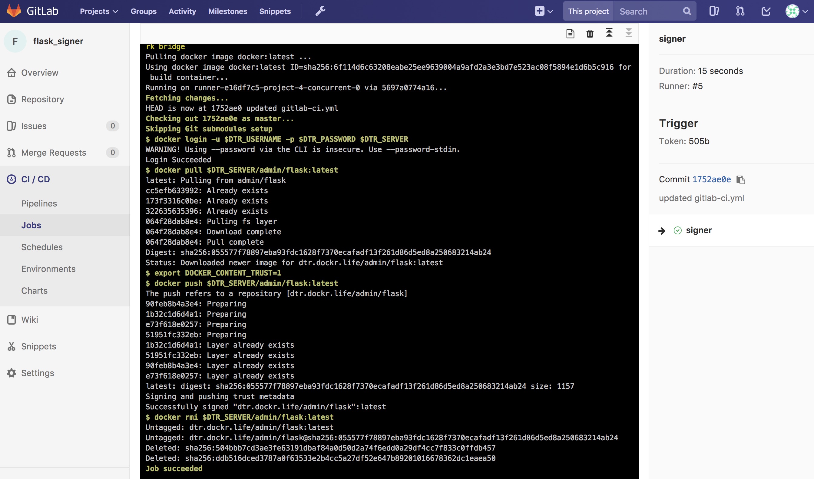
Now the final step is to create a Pipeline Trigger for the Image Signing project. Use the webhook with an “Image promoted from repository” event.
Summary
Automating a Secure Supply Chain is not that difficult. After following this reference architecture, GitLab is setup with at least two projects. One is for the code, Dockerfile, and stack yaml. A second is for the image signing component. MSR also has two repositories. One is for the private build, and a second is for the signed promoted image.
The main goal is to have an image that is both Promoted, based on a good scan, and Signed, with Notary, in an automated fashion.

While specific tools were discussed, there are a few takeaways from this reference architecture:
- Automate all the things
- Pick a Known Good Source
- Leverage Image scanning and promotion
- Sign the Image
- No human will build or deploy code headed to production!
Here is another look at the workflow.
Consider the ideas and feel free to change the individual tools out for what your organization has.
Warning
Mirantis stopped maintaining this documentation set as of 2021-07-21, in correlation with the End of Life date for MKE 3.2.x and MSR 2.7.x. The company continues to support MCR 19.03.x and its documentation.
For the latest MKE, MSR, and MCR product documentation, refer to:
Storage
A variety of storage solutions exist for enterprise use, and a rapidly growing container ecosystem continues to provide many more storage solutions for future consideration. Storage must be highly adaptable and configurable to achieve the optimal platform for containerized workloads. Docker Enterprise provides a pluggable “batteries included, but replaceable” architecture that allows for the implementation and configuration of storage solutions that best meet your requirements across the entire Software Delivery Supply Chain.
An Introduction to Storage for Docker Enterprise
Introduction
The Docker Enterprise platform delivers a secure, managed application environment for developers and operations personnel to build, ship, and run enterprise applications and custom business processes. This platform often requires storage across the different phases of the Software Delivery Supply Chain.
A variety of storage solutions exist for enterprise use and a rapidly growing container ecosystem continues to provide many more storage solutions for future consideration. The growing ecosystem of new storage options combined with a need to utilize existing storage investments brings forth the critical requirement that storage must be highly adaptable and configurable to achieve the optimal platform for containerized workloads.
The Docker Enterprise platform provides a default prescriptive storage configuration ‘out of the box.’ This allows consumers to begin building, shipping, and running containerized applications quickly.
However, and perhaps most importantly, Docker Enterprise provides a pluggable “batteries included, but replaceable” architecture that allows for the implementation and configuration of storage solutions that best meet your requirements across the entire Software Delivery Supply Chain. This pluggable architecture approach for implementing the storage of choice also includes the ability to interchange other critical enterprise infrastructure services in a pluggable fashion such as networking, logging, authentication, authorization, and monitoring.
Overview
Docker separates storage use cases within the Docker Enterprise Platform into three categories:
Docker image run storage (storage drivers)
Storage used for reading image filesystem layers from a running container state typically require high IOPS which in turn drivers the underlying storage requirements. These higher performance disk requirements often have higher costs and reduced scalability, so features such as redundancy or resiliency are sometimes traded off to manage the storage economics.
Persistent data container storage (volumes)
Containers often require persistent storage for using, capturing, or saving data beyond a specific container’s life cycle. Utilizing volume storage is selected to keep data for future use or permit shared consumption by other containers or services. The many volume storage solutions available provide features such as high availability, scalable performance, shared filesystems, and reliable read/write filesystem protocols that are supported by Docker, OS vendors, and other storage vendors.
Registry “at rest” image storage (registry)
When images are stored at rest on disk for cataloging and e-discovery purposes, as is the case for Mirantis Secure Registry (MSR), key storage service metrics will likely revolve around scalability, costs, redundancy, and resiliency. In the case of Mirantis Secure Registry, acute attention will likely be toward lower cost per terabyte and higher scalability. Lower IOPS and perhaps fewer filesystem protocols are often traded out in exchange for lower costs.
Each storage tier has specific storage requirements to achieve expected service levels across the different stages of the Software Delivery Supply Chain of a Docker Enterprise platform. Speed, scalability, high availability, recoverability, and costs are just a few of the many storage metrics that can help determine the optimal storage choice for each phase where storage is consumed.
This document will explore each of these three distinct storage tiers — local image storage, volume storage, and registry storage — in further detail.
Image Storage
On each node of the Docker Enterprise cluster, storage drivers (previously known as graph drivers) interface local storage with the Mirantis Container Runtime. Performance is almost always considered the key metric for image storage. OS support and resiliency are typical requirements as well.
Storage drivers must be able to act as a local registry to store and retrieve copies of image layers that make up full images. Storage drivers also act as a caching mechanism to improve storage efficiency and download times for images within the local registry. They provide a Copy on Write (CoW) filesystem which is appended to a set of read-only image layers that constitute a running container. In acceptable I/O time frames, storage drivers must also be able to reliably read into memory the sets of image layers that make a running container on the Mirantis Container Runtime. Storage drivers are arguably the workhorse of all storage used within the Docker Enterprise platform. Choosing an incorrect storage driver or misconfiguration can significantly impact expected service levels of the entire Software Delivery Supply Chain.
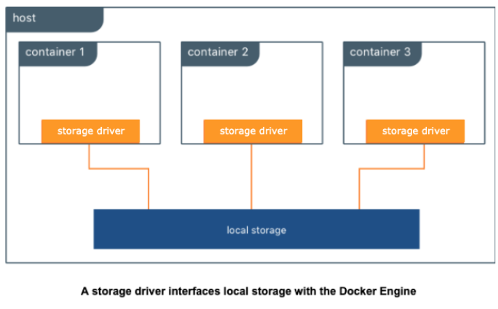
Storage Drivers also supply a writeable CoW (Copy on Write) image layer on top of read-only filesystem layers of an image that are started as a running container. The CoW filesystem created at image runtime is assigned a unique filesystem layer ID; this unique CoW layer ID is ephemeral and does not persist or stay with the original image after each iteration of that image being run as a container. The default execution of an image as a container is ephemeral, meaning the container runtime does not automatically persist the CoW layer as part of the original image. You can save a running container with its unique CoW layer into a new image where the CoW is then transformed to an additional read-only layer on top of the original running read image layers. While it is possible to save the CoW contents of a running container as a new image itself, doing so as a means to persist data isn’t scalable, pragmatic, or practical. The CoW filesystem is most often successfully utilized when used as a means to expand or iterate a current image state to include necessary components or code to expand the image service requirements into a repeatable and reusable image.
Currently, the only supported storage drivers available are built into the Mirantis Container Runtime. Thus, the host OS has some influence on available, supported storage drivers. There is growing interest in experimental support using pluggable volumes, but none are currently recommended or available.
Selecting Storage Drivers
In previous versions, several factors influenced the selection of a storage driver and different Linux distributions had different preferred storage drivers. The promotion of the overlay2 storage driver as the default storage driver for all Linux distributions has made choosing a storage driver much easier. The majority of supported Linux distributions default to using the overlay2 storage driver for Mirantis Container Runtime.
It was chosen as the default storage driver due to its mainline kernel support, speed, capabilities, and ease of setup compared to alternate storage drivers.
For the most stable and hassle-free Docker experience use the overlay2 storage driver. When Docker is installed and started for the first time, a storage driver is selected based on your operating system and filesystem’s capabilities. Straying from this default may increase your chances of encountering bugs and other issues. Follow the configuration specified in the Compatibility Matrix. Alternate storage drivers may be available for your Linux distribution but their use may be deprecated in future releases in favor of standardizing on the overlay2 driver.
There are two versions of overlayFS drivers available, Overlay and Overlay2. The usage of the overlay storage driver has been deprecated in favor of overlay2. Overlay has known documented issues with inode exhaustion and commit exhaustion. The overlay2 storage driver does not suffer from the same inode exhaustion issues as overlay. To use overlay2, you need version 4.0 or higher of the Linux kernel, or RHEL or CentOS using version 3.10.0-514 and above. For more details on how Docker utilizes storage drivers, go to the documentation storage drivers page in the additional resources section.
Volume Storage
Volume storage is an extremely versatile storage solution that can be used to do many things. Generally, volume storage provides ways for an application or user to store data generated by a running container. It extends beyond the life or boundaries of an existing or running container. This storage use case is commonly referred to as persistent storage. Persistent storage is an extremely important use case, especially for things like databases, image files, file and folder sharing, and big data collection activities. Volume storage can also be used to do other interesting things such as provide easy access to secrets (for example, backed by KeyWhiz) or provide configuration data to a container from a key/value store. No matter where the data comes from, this information is translated by the volume driver plugin from the backend into a filesystem that can be accessed by normal tools meant to interact with the filesystem.
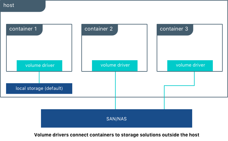
Many enterprises consume storage from various storage systems such as SAN and NAS arrays. These solutions often provide increased performance and availability as well as advanced storage features such as thin provisioning, replication, deduplication, encryption, and compression. They usually offer storage monitoring and management as well.
Volume drivers are used to connect storage solutions to the Docker Enterprise platform. You can use existing drivers or write drivers to allow the underlying storage to interface with the underlying APIs of the Docker Enterprise platform. A variety of volume driver solutions exist and can be plugged into and consumed within Docker Platform. There are volume storage projects from the open source community, and there are commercially-supported volume drivers available from storage vendors. Many volume driver plugins available today are software-defined and provide feature sets that are agnostic to the underlying physical storage.
For a list of volume plugins, go to the volume plugins documentation page in the additional resources section.
Docker references a list of tested and Certified Volume Storage plugins from partners on hub. Among this list, we can highlight:
- Trident from NetApp
- HPE Nimble
- Nutanix DVP
- Pure Storage
- vSphere Storage
- DataCore SDS
- NexentaEdge
- BlockBridge
For the full list of Docker Certified Storage plugins, go to the link in the additional resources section.
Docker Kubernetes Services also bring the best from Kubernetes world in order to provide containers with Persistent Storage:
- Static and Dynamic Persistent Volume provisioning
- Block Level-access with iSCSI
- FlexVolume and CSI (Container Storage Interface) drivers
- File and Block storage from various cloud providers including Amazon EBS & EFS , Azure Disks and File Storage.
- NFS shares
For a list of storage options available through Docker Kubernetes Service, go to the kubernetes storage options documentation page in the additional resources section.
Registry Storage
Registry storage is the backing storage for a running image registry instance such as Mirantis Secure Registry or Docker Hub. Mirantis Secure Registry is an on-premises image registry service within the Docker Enterprise platform. Docker Hub is the public SaaS image registry provided by Docker. Registry Storage, regardless of location, does not typically require high I/O performance metrics, but they almost always require resiliency, scalability, and low cost economics to meet expected SLAs. The public Docker Hub image registry service is a specific example where these metric choices are clearly identifiable. Docker Hub requirements for faster push and pull speeds are secondary to metrics such as scalability, resiliency, and economics. Combined, these three metrics enable Docker to efficiently manage and support the most popular Docker container registry in the industry.
There are several available supported registry storage backend options for Mirantis Secure Registry such as NFSv4, NFSv3, Amazon S3, S3 Compliant Alternatives, Azure Storage (Blob), Google Cloud Storage, OpenStack Swift, and local filesystem. For an up to date list of backing storage options for Mirantis Secure Registry, refer to the Compatibility Matrix. These storage options can provide the same registry SLAs required by large scale operations like Docker Hub. Local storage is also an available backing storage option and is the “out of the box” default for the Docker Enterprise platform. Ultimately, local file system storage options cannot offer similar or improved service levels in the order of magnitude that object storage can provide due to filesystem restrictions such as inode limits or filesystem protocol restrictions.
Docker images are immutable, read only, and attached with metadata. These digital characteristics relate very well with object storage features offered in S3, Azure, etc. Object storage also provides many additional digital management features that can enhance the overall image storage experience in addition to what Mirantis Secure Registry provides for managing your application images. For example, object storage can provide additional service catalog items such as multi-dc or multi-region image replication to support Disaster Recovery and Continuous Availability designs, or offer additional built-in native redundancy for enhanced image availability, backup and restore solutions, or common API capabilities. It can also provide encryption at rest and client side encryption. Because of these additional features and advantages that object storage solutions provide, it’s recommended that Mirantis Secure Registry be configured to utilize an object storage backing solution for highly available installations. Object storage also provides additional image pulling performance benefits due to the Mirantis Secure Registry serving the contents directly from the object stores by default. If HA is not required, then a single local filesystem is prepared as the default backing storage configuration for Mirantis Secure Registry, but this configuration can be changed to use a backing storage solution of your choice.
Often NFS or NFS-like file share solutions are used as an alternative backing storage solution to Object Storage. These file share based solutions can also fulfill the backing storage requirement for High Availability of Mirantis Secure Registry. Because many enterprises are very familiar with NFS or similar shared filesystem storage solutions, there are natural tendencies to use shared filesystems over object storage solutions. There are disadvantages of using NFS or comparable shared filesystems as the backing storage for your Docker images:
- NFS has many guarantees that erodes performance with too much unnecessary synchronization.
- NFS essentially mimics a filesystem, often masking low level errors because it has no way to mitigate them.
- NFSv3 doesn’t possess a native security model within.
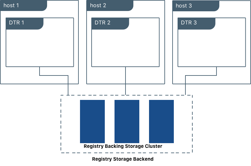
Plugin storage options are not currently supported for registry storage, but there are a number of on-premises, S3 compliant backing storage options that are also a good fit for Mirantis Secure Registry. Many partners leverage built-in S3-compliant API compatibility support as a way to have their storage service supported without having to write new code.
When planning a production-grade installation of Mirantis Secure Registry on-premises, it’s best to configure the image registry service as a highly available and redundant service, making the ability to change the backing storage of choice an important feature of the Mirantis Secure Registry. All highly available Mirantis Secure Registry configurations do require a backing storage solution that can support a clustered set of containers requesting parallel asynchronous write requests to the physical storage itself. Mirantis Secure Registry does not assume, manage, or control any write-locking mechanisms that takes place for image/filesystem data being written to the physical underlying storage. Therefore, writes must be managed independently by the storage protocol of the backing storage itself.
Conclusion
When choosing storage solutions for the Docker Enterprise Platform, consider the following:
- Typically, containers are described and categorized to run as one of two separate, distinct states — stateful and stateless. A stateful service holds requirements for capturing and storing persistent data during a container runtime. For example, a database that presents database tables on physical storage within a container for the purpose of writing or updating data is considered a stateful service. Stateless containers do not possess the same requirements for data persistence within a container runtime. Any data captured or generated during runtime does not exist or does not have to be recorded. When planning for image builds, it is recommended that you determine the state of each application or service within a container. Then, determine what the storage requirements are as well as the consumption possibilities for each container within the application stack. Also determine what storage options are available or have to be purchased to provide the best results.
- Consider implementing a service catalog that captures all labels, filters, and constraints assigned to your storage hosts. Capturing all of these definitions will help eliminate overlap or isolate resource gaps in your Docker Platform environment and allow you to model and plan out the most efficient and informed orchestration methods available across the entire Software Delivery Supply Chain.
- Regardless of container state, every container possesses a writable Copy on Write (CoW) filesystem that is presented by each Docker host. As previously covered, storage drivers are not designed to accommodate data persistence and sharing, thus misinterpretation and misuse of this space as a means to persist and reuse data can lead to unexpected results and data loss. Strongly consider early in your planning stages that applications should not use this writeable space as a means to persist data beyond the container life cycle.
Warning
Mirantis stopped maintaining this documentation set as of 2021-07-21, in correlation with the End of Life date for MKE 3.2.x and MSR 2.7.x. The company continues to support MCR 19.03.x and its documentation.
For the latest MKE, MSR, and MCR product documentation, refer to:
App Development
Whether you are deploying new applications with Docker containers or modernizing traditional applications, these reference architectures will explain what to include in the Docker image, what configuration to put in containers, how to store assets for building images and configuration in version control, how service discovery works, and explore load balancing.
Design Considerations and Best Practices to Modernize Traditional Apps (MTA)
Introduction
The Docker Containers as a Service (CaaS) platform delivers a secure, managed application environment for developers to build, ship, and run enterprise applications and custom business processes. Containerize legacy apps with Docker Enterprise Edition (EE) to reduce costs, enable portability across infrastructure, and increase security.
What You Will Learn
In an enterprise, there can be hundreds or even thousands of traditional or legacy applications developed by in-house and outsourced teams. Application technology stacks can vary from a simple Excel macro, to multi-tier J2EE, all the way to clusters of elastic microservices deployed on a hybrid cloud. Applications are also deployed to several heterogeneous environments (development, test, UAT, staging, production, etc.), each of which can have very different requirements. Packaging an application in a container with its configuration and dependencies guarantees that the application will always work as designed in any environment.
In this document you will learn best practices for modernizing traditional applications with Docker EE. It starts with high-level decisions such as what applications to Dockerize and methodology, then moves on to more detailed decisions such as what components to put in images, what configuration to put in containers, where to put different types of configuration, and finally how to store assets for building images and configuration in version control.
What Applications to Modernize?
Deciding which applications to containerize depends on the difficulty of the Dockerizing versus the potential gains in speed, portability, compute density, etc. The following sections describe, in order of increasing difficulty, different categories of components and approaches for containerizing them.
Stateless
In general, components which are stateless are the easiest to Dockerize because there is no need to take into account persistent data such as with databases or a shared filesystem. This is also a general best practice for microservices and allows them to scale easier as each new instance can receive requests without any synchronization of state.
Some examples of these are:
- Web servers with static resources — Apache, Nginx, IIS
- Application servers with stateless applications — Tomcat, nodeJS, JBoss, Symphony, .NET
- Microservices — Spring Boot, Play
- Tools — Maven, Gradle, scripts, tests
Stateful
Components which are stateful are not necessarily harder to Dockerize. However, because the state of the component must be stored or synchronized with other instances, there are operational considerations.
Some examples of these are:
Application servers with stateful applications — There is often a need to store user sessions in an application. Two approaches to handling this case are to use a load balancer with session affinity to ensure the user always goes to the same container instance or to use an external session persistence mechanism which all container instances share. There are also some components that provide native clustering such as portals or persistence layer caches. It is usually best to let the native software manage synchronization and states between instances. Having the instances on the same overlay network allows them to communicate with each other in a fast, secure way.
Databases — Databases usually need to persist data on a filesystem. The best practice is to only containerize the database engine while keeping its data on the container host itself. This can be done using a host volume, for example:
$ docker run -d \
  -v /var/myapp/data:/var/lib/postgresql/data \
  postgres
Applications with shared filesystems - Content Management Systems (CMS) use filesystems to store documents such as PDFs, pictures, Word files, etc. This can also be done using a host volume which is often mounted to a shared filesystem so several instances of the CMS can access the files simultaneously.
Complex Product Installation
Components that have a complex production installation are usually the hardest to Dockerize because they cannot be captured in a Dockerfile.
Some examples of these are:
- Non-scriptable installation — These can include GUI-only installation/configuration or products that require multi-factor authentication.
- Non-idempotent installation process — Some installation processes can be asynchronous where the installation script has terminated but then starts background processes. The completion of the entire installation process includes waiting for a batch process to run or a cluster to synchronize without returning a signal or clear log message.
- Installation with external dependencies — Some products require an external system to reply for downloading or activation. Sometimes for security reasons this can only be done on a specific network or for a specific amount of time making it difficult to script the installation process.
- Installation that requires fixed IP address — Some products require a fixed IP address for a callback at install time but can then be configured once installed to use a hostname or DNS name. Since container IP address are dynamically generated, the IP address could be difficult to determine at build time.
In this case instead of building an image from a Dockerfile the image should be build by first running a base container, installing the product, and then saving the changes out to an image. An example of this is:
$ docker commit -a "John Smith" -m "Installed CMS" mycontainer cms:2
Note
Tools or Test Container. When debugging services that have
dependencies on each other, it is often helpful to create a
container with tools to test connectivity or the health of a
component. Common cases are network tools like telnet, netcat,
curl, wget, SQL clients, or logging agents. This avoids adding
unnecessary debugging tools to the containers that run the production
loads. One popular image for this is the netshoot troubleshooting
container.
Methodology
Two different use cases for modernizing traditional applications are:
- End of Life — Containerizing an application without further development
- Continued Development — Containerizing an application that has ongoing development
Depending on the use case, the methodology for containerizing the application can change. The following sections discuss each of them.
End of Life
An application that is at its end of life has no further development or upgrades. There is no development team, and it is only maintained by operations. There is no requirement to deploy the application in multiple environments (development, test, uat, staging, production) because there are no new versions to test. To containerize this type of application, the best solution would be to copy the contents of the existing server into an image. The Docker community provides open source tools such as Image2Docker to do this, which will create a Dockerfile based upon analysis of existing Windows or Linux machines:
Once a Dockerfile is generated with these tools, it can then be further modified and operationalized depending on the complexity of application. An image can then be built from the Dockerfile and run by an operations team in Docker EE.
Continued Development
If the application will continue to be actively developed, then there are other considerations to take into account. When containerizing an application it might be tempting to refactor, re-architect, or upgrade it at the same time. We recommend starting with a “lift and shift” approach where the application is first containerized with the minimal amount of changes possible. The application can be regression tested before further modifications are made. Some rules of thumb are:
- Keep the existing application architecture
- Keep the same versions of OS, components, and application
- Keep the deployment simple (static and not elastic)
Once the application is containerized, it will then be much easier and faster to implement and track changes such as:
- Upgrade to a newer version of application server
- Refactor to microservices
- Dynamically scale or elastic deployment
In a “lift and shift” scenario the choice of base libraries or components such as an application server or language version as well as the underlying OS are already determined by the legacy application. The next step is determining the best way to integrate this “stack” into a Docker image. There are several approaches to this depending on the commonality of the components, the customization of components in the application, and adherence to any enterprise support policies. There are different ways to obtain a stack of components in an image:
- Open source image — A community image from Docker Hub
- Docker Certified — A certified image from Docker Hub, built with best practices, tested and validated against the Docker EE platform and APIs, pass security requirements, and are collaboratively supported (eg, Splunk Enterprise)
- Verified Publisher — A verified image from Docker Hub, published and maintained by a commercial entity (eg, Sysdig Inspect)
- Official image — Official Images are a curated set of Docker open source and “drop-in” solution repositories hosted on Docker Hub (eg, nginx, alpine, redis)
- Enterprise image — An internal image built, maintained, and distributed by an enterprise-wide devops team
- Custom image — A custom image built for the application by the development team
While the open source and certified images can be pulled and used “as is” the enterprise and custom images must be built from Dockerfiles. One way of creating an initial Dockerfile is to use the Image2Docker tools mentioned before. Another option is to copy the referenced Dockerfile of an image found in Docker Hub or Store.
The following table summarizes the advantages and disadvantages of each choice:
| Open-source | Certified | Enterprise | Custom | |
|---|---|---|---|---|
| Advantages |
|
|
|
|
| Disadvantages |
|
|
|
|
A common enterprise scenario is to use a combination of private and custom images. Typically, an enterprise will develop a hierarchy of base images depending on how diverse their technology stacks are. The next section describes this concept.
Image Hierarchy
Docker images natively provide inheritance. One of the benefits of deriving from base images is that any changes to a base or upstream image are inherited by the child image simply by rebuilding that image without any change to the child Dockerfile. By using inheritance, an enterprise can very simply enforce policies with no changes to the Dockerfiles for their many applications. Typically, an enterprise will develop a hierarchy of base images depending on how diverse their technology stacks are. The following is an example of an image hierarchy.
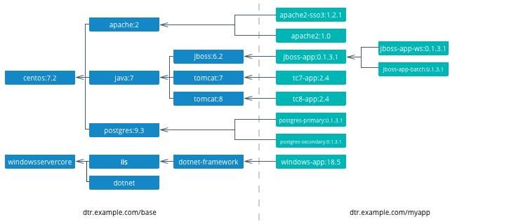
On the left are the enterprise-wide base images typically provided by the global operations team, and on the right are the application images. Even on the application side, depending on how large an application or program is, there can be a hierarchy as well.
Note
Create a project base image. In a project team with a complicated application stack there are often common libraries, tools, configurations, or credentials that are specific to the project but not useful to the entire enterprise. Put these items in a “project base image” from which all project images derive.
What to Include in an Image
Another question that arises when modernizing is what components of an application stack to put in an image. You can include an entire application stack such as the the official GitLab image, or you can do the opposite, which would be to break up an existing monolithic application into microservices, each residing in its own image.
Image Granularity
In general, it is best to have one component per image. For example, a reverse proxy, an application server, or a database engine would each have its own image. What about an example where several web applications (e.g. war) are deployed on the same application server? Should they be separated and each have its own image or should they be in the same image? The criteria for this decision are similar to non-containerized architectural decisions:
- Release Lifecycle — Are the application release schedules tightly coupled or are they independent?
- Runtime Lifecycle — If one application stops functioning should all application be stopped?
- Scalability — Do the applications need to be scaled separately or can they be scaled together?
- Security — Does one application need a higher level of security such as TLS?
- High Availability — Is one application mission critical needing redundancy and the others can tolerate a single point of failure and downtime?
Existing legacy applications will already have groupings of applications per application server or machine based upon operational experience and the above criteria. In a pure “lift and shift” scenario for example the entire application server can be put in one container.
Similarly with microservices, the same criteria apply. For example, consider a microservice that depends on a logging agent to push logs to a centralized logging database. The following diagram shows two different strategies for a high availability deployment for the microservice.
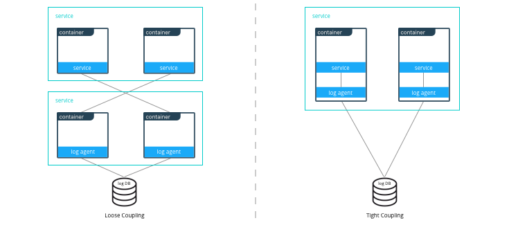
If the microservice and logging agent are loosely coupled, they can be run in separate containers such as in the configuration on the left. However, if the service and the logging agent are tightly coupled and their release lifecycles are identical, then putting the two processes in the same container can simplify deployments and upgrades as illustrated in the configuration on the right. To manage multiple processes there are several lightweight init systems for containers such as tini, dumb-init, and runit.
Hardening Images
A question that arises frequently is which parts of the component should go into an image? The engine or server, the application itself, the configuration files? There are several main approaches:
- Create only a base image and inject the things that vary per release or environment
- Create an image per release and inject the things that vary per environment
- Create an image per release and environment
In some cases, a component does not have an application associated with it or its configuration does not vary per environment, so a base image is appropriate. An example of this might be a reverse proxy or a database. In other cases such as an application which requires an application server, using a base image would require mounting a volume for a certain version of an application.
The following table summarizes the advantages and disadvantages of each choice:
| Base Image | Release Image | Environment Image | |
|---|---|---|---|
| What’s inside the image | OS, middleware, dependencies | Base image, release artifacts, configuration generic to the environment | Release image, configuration specific to the environment |
| What’s outside the image | Release artifacts, configuration, secrets | Configuration specific to the environment, secrets | Secrets |
| Advantages | Most flexible at run time, simple, one image for all use cases | Some flexibility at run time while securing a specific version of an application | Most portable, traceable, and secure as all dependencies are in the image |
| Disadvantages | Less portable, traceable, and secure as dependencies are not included in the image | Less flexible, requires management of release images | Least flexible, requires management of many images |
| Examples | Tomcat
dtr.example.com/base/tomcat7:3 |
Tomcat + myapp-1.1.war
dtr.example.com/myap p/tomcat7:3 |
Tomcat + myapp-1.1.war + META-INF/context.xml
dtr.example.com/myapp/tomcat7:3-dev |
Usually a good choice is to use a release image. This gives the best combination of a sufficiently immutable image while maintaining the flexibility of deploying to different environments and topologies. How to configure the images per different environments is discussed in the next section.
Configuration Management
A single enterprise application will typically have four to twelve
environments to deploy on before going into production. Without Docker
installing, configuring, and managing these environments, a
configuration management system such as Puppet, Chef, Salt, Ansible,
etc. would be used. Docker natively provides mechanisms through
Dockerfiles and docker-compose files to manage the configuration of
these environments as code, and thus configuration management can be
handled through existing version control tools already used by
development teams.
Environment Topologies
The topologies of application environments can be different in order to optimize resources. In some environments it doesn’t make sense to deploy and scale all of the components in an application stack. For example, in functional testing only one instance of a web server is usually needed whereas in performance testing several instances are needed, and the configuration is tuned differently. Some common topologies are:
- Development — A single instance per component, debug mode
- Integration, Functional testing, UAT, Demonstration - A single instance per component, small dataset, and integration to test external services, debug mode
- Performance Testing — Multiple instances per component, large dataset, performance tuning
- Robustness Testing — Multiple instances per component, large dataset, integration to test external services, batch processing, and disaster recovery, debug mode
- Production and Staging — Multiple instances per component, production dataset, integration to production external services, batch processing, and disaster recovery, performance tuning
The configuration of components and how they are linked to each other is
specified in the docker-compose file. Depending on the environment
topology, a different docker-compose can be used. The
extends
feature can be used to create a hierarchy of configurations. For
example:
myapp/
  common.yml <- common configurations
  docker-compose-dev.yml <- dev specific configs extend common.yml
  docker-compose-int.yml
  docker-compose-prod.yml
Configuration Buckets
In a typical application stack there are tens or even hundreds of
properties to configure in a variety of places. When building images and
running containers or services there are many choices as to where and
when a property should be set depending on how that property is used. It
could be in a Dockerfile, docker-compose file, environment variable,
environment file, property file, entry point script, etc. This can
quickly become very confusing in a complicated image hierarchy
especially when trying to adopt DRY principles. The following table
shows some common groupings based on lifecycles to help determine where
to put configurations.
| When | What | Where | Examples |
|---|---|---|---|
| Yearly build time | Enterprise policies and tools | Enterprise base image Dockerfiles | FROM centos6.6RUN yum -y --noplugins install bzip2 tar sudo curl net-tools |
| Monthly build time | Application policies and tools | Application base image Dockerfiles | COPY files/dynatrace-agent-6.1.0.7880-unix.jar /opt/dynatrace/ |
| Monthly/weekly build time | Application release | Release image Dockerfiles | COPY files/MY_APP_1.3.1-M24_1.war /opt/jboss/standalone/deployments/ |
| Weekly/daily deploy time | Static environment configuration | Environment variables, docker-compose, .env | environment:-MOCK=true-GATEWAY_URL=https://example.com/ws |
| Deploy time | Dynamic environment configuration | Secrets, entrypoint.sh, vault, CLI, volumes | $ curl -H "X-Vault-Token: f3b09679-3001-009d-2b80-9c306ab81aa6" -X GET https://vlt.example.com:8200/v1/secret/db |
| Run time | Elastic environment configuration | Service discovery, profiling, debugging, volumes | $ consul-template -consul consul.example.com:6124 -template "/tmp/nginx.ctmpl:/var/nginx/nginx.conf:service nginx restart" |
The process of figuring out where to configure properties is very similar to code refactoring. For example, properties and their values that are identical in child images can be abstracted into a parent image.
Secrets Management
Starting with Mirantis Container Runtime 17.03 (and Docker CS Engine 1.13), native secrets management is supported. Secrets can be created and managed using RBAC in Docker Enterprise. Although Docker EE can manage all secrets, there might already be an existing secrets management system, or there might be the requirement to have one central system to manage secrets in Docker and non-Docker environments. In these cases, a simple strategy to adopt for Docker environments is to create a master secret managed by Docker EE which can then be used in an entry point script to access the exiting secrets management system at startup time. The recovered secrets can then be used within the container.
Dockerfile Best Practices
As the enterprise IT landscape and the Docker platform evolve, best practices around the creation of Dockerfiles have emerged. Docker keeps a list of best practices on docs.docker.com.
Docker Files and Version Control
Docker truly allows the concept of “Infrastructure as Code” to be applied in practice. The files that Docker uses to build, ship, and run containers are text-based definition files and can be stored in version control. There are different text-based files related to Docker depending on what they are used for in the development pipeline.
- Files for creating images — Dockerfiles,
docker-compose.yml,entrypoint.sh, and configuration files - Files for deploying containers or services —
docker-compose.yml, configuration files, and run scripts
These files are used by different teams from development to operations in the development pipeline. Organizing them in version control is important to have an efficient development pipeline.
If you are using a “release image” strategy, it can be a good idea to separate the files for building images and those used for running them. The files for building images can usually be kept in the same version control repository as the source code of an application. This is because release images usually follow the same lifecycle as the source code.
For example:
myapp/
  src/
  test/
  Dockerfile
  docker-compose.yml <- build images only
  conf/
    app.properties
    app.xml
    entrypoint.sh
Note
A docker-compose file with only
build
configurations for different components in an application stack can
be a convenient way to build the whole application stack or
individual components in one file.
The files for running containers or services follow a different lifecycle, so they can be kept in a separate repository. In this example, all of the configurations for the different environments are kept in a single branch. This allows for very simple version control strategy, and configurations for all environments can be viewed in one place.
For example:
myapp/
  common.yml
  docker-compose-dev.yml
  docker-compose-int.yml
  docker-compose-prod.yml
  conf/
    dev.env
    int.env
    prod.env
However, this single branch strategy quickly becomes difficult to maintain when different environments need to deploy different versions of an application. A better strategy is to have each environment’s run configuration is in a separate branch. For example:
myapp/ <- int branch
  docker-compose.yml
  conf/
    app.env
The advantages of this are multiple:
- Tags per release can be placed on a branch, allowing an environment to be easily rolled back to any prior tag.
- Listing the history of changes to the configuration of a single environment becomes trivial.
- When a new application release requires the same modification to all of the different environments and configuration files, it can be done using the merge function from the version control as opposed to copying and pasting the changes into each configuration file.
Repositories for Large Files
When building Docker images, inevitably there will be large binary files that need to be used. Docker build does not let you access files outside of the context path, and it is not a good idea to store these directly in a version control, especially a distributed one such as git, as the repositories will rapidly become too large and unwieldy.
There are several strategies for storing large files:
- Web Server — They can be stored on a shared filesystem, served by
a web server, and then accessed by exposing them with the
ADD <URL> <dest>command in the Dockerfile. This is the easiest method to setup, but there is no support for versions of files or RBAC on files. - Repository Manager — They can be stored as files in a repository manager such as Nexus or Artifactory, which provide support for versions and RBAC.
- Centralized Version Control — They can be stored as files in a centralized version control system such as SVN, which eliminates the problem of pulling all versions of large binary files.
- Git Large File Storage — They can be stored using Git LFS. This gives you all of the benefits of git, and the Docker build is under one context. However, there is a learning curve to using Git LFS.
Summary
This document discusses best practices for modernizing traditional applications to Docker. It starts with high-level decisions such as what applications to Dockerize and methodology, then moves on to more detailed decisions such as what components to put in images, what configuration to put in containers, where to put different types of configuration, and finally how to store assets for building images and configuration in version control. Follow these best practices to modernize your traditional applications.
Modernizing Traditional .NET Framework Applications
Introduction
Docker containers have long been used to enable the development of new applications leveraging modern application architectural patterns like microservices, but Docker containers are not just for new applications. Traditional or Brownfield applications can also be migrated to containers and Docker Enterprise Edition to take advantage of the benefits that Docker Enterprise provides.
What You Will Learn
This reference architecture provides guidance and examples for modernizing traditional .NET Framework applications to Docker Enterprise Edition. You will learn to identify the types of .NET Framework applications that are good candidates for containerization, the “lift-and-shift” approach to containerization with little to no code changes, how to get started, and guidance around various .NET Framework applications and Windows Server containers, including handling Windows Integrated Authentication, networking, logging, and monitoring.
This document focuses primarily on custom .NET Framework applications. It does not cover commercial off-the-shelf (COTS) .NET Framework applications such as SharePoint and Sitecore. Although it may be possible to run these COTS applications in Docker Enterprise, guidance on how to do so for these applications are beyond the scope of this reference architecture. Also, .NET Core is not covered. All references to .NET applications refer to .NET Framework applications and not .NET Core applications.
Refactoring to microservices architectures is also not covered in this document. At the end of the containerization process discussed in this reference architecture, your .NET Framework application will be ready should you decide to refactor parts of the application to microservices.
Note
Before continuing, please become familiar with the reference architecture Design Considerations and Best Practices to Modernize Traditional Apps
See the caveats section for additional important information to be aware of.
Caveats
Before you begin there are some things to be aware of that will impact your deployment of applications on Docker Enterprise.
Note
Windows Server 2019 is the recommended platform to run Windows containerized applications. Versions prior to Windows Server 2016 do not support running containers of any type. Windows 2016, while capable of supporting containers, is not Microsoft’s recommended container host platform.
Desktop based apps with graphical user interfaces (GUIs) cannot yet be containerized
Due to the unique nature of certain Windows features (e.g. networking, security, file system) there are several items of note regarding the deployment of a Docker service. Below is a list of these issues including the current “best practices” used to work around them.
Networking (see Example compose file for a service running on Windows nodes below)
For services that need to be reachable outside the swarm, Linux containers are able to use Docker swarm’s ingress routing mesh. However, Windows Server 2016 does not currently support the ingress routing mesh. Therefore Docker services scheduled for Windows Server 2016 nodes that need to be accessed outside of swarm need to be configured to bypass Docker’s routing mesh. This is done by publishing ports using
hostmode which publishes the service’s port directly on the node where it is running.Additionally, Docker’s DNS Round Robin is the only load balancing strategy supported by Windows Server 2016 today; therefore, for every Docker service scheduled to these nodes, the
--endpoint-modeparameter must also be specified with a value ofdnsrr.When running Docker for Windows there is an issue related to container IP addresses. The IP address shown when using the
docker inspectcommand for a container is incorrect. To browse a web site or api running in a container you must use thedocker execcommand and query the IP address from within the container (e.g.ipconfig). Also, port assignments are ignored by Docker for Windows when running Windows containers (e.g.docker run -p 8080:80). Run the example app to illustrate this issue.Docker Objects
Configs use the
SYSTEMandADMINISTRATORpermissions- When using a Docker Config object to replace the
web.configfile (ASP.Net apps), IIS will not be able to consume the file. IIS requires (by default)BUILTIN\IIS_IUSRScredentials applied to files it will read/write to. - Due to the fact that Docker Config objects are attached after the
container is created, assigning rights to the application folder
during a
docker buildwill not solve this problem. Files added by the Config will retain their original credentials (ADMINISTRATOR&SYSTEM).
- When using a Docker Config object to replace the
Secrets stored on node temporarily
- Microsoft Windows has no built-in driver for managing RAM disks,
so within running Windows containers, secrets are persisted in
clear text to the container’s root disk. However, the secrets are
explicitly removed when a container stops. In addition, Windows
does not support persisting a running container as an image using
docker commitor similar commands. - On Windows, we recommend enabling BitLocker on the volume containing the Docker root directory on the host machine to ensure that secrets for running containers are encrypted at rest.
- Secret files with custom targets are not directly bind-mounted
into Windows containers, since Windows does not support
non-directory file bind-mounts. Instead, secrets for a container
are all mounted in
C:\ProgramData\Docker\internal\secrets(an implementation detail which should not be relied upon by applications) within the container. Symbolic links are used to point from there to the desired target of the secret within the container. The default target isC:\ProgramData\Docker\secrets. - When creating a service which uses Windows containers, the options
to specify UID, GID, and mode are not supported for secrets.
Secrets are currently only accessible by administrators and users
with
systemaccess within the container.
- Microsoft Windows has no built-in driver for managing RAM disks,
so within running Windows containers, secrets are persisted in
clear text to the container’s root disk. However, the secrets are
explicitly removed when a container stops. In addition, Windows
does not support persisting a running container as an image using
AD authentication requires use of Integrated Windows Authentication
Windows node must be joined to the AD domain
Common base images for Windows applications
- Additional Windows Features may be required depending on app requirements
ASP.Net applications: microsoft/aspnet
WCF Services: microsoft/iis
Console Applications: microsoft/dotnet-framework
.Net build tools: microsoft/dotnet-framework
- Used for multi-stage builds (use the SDK variants)
ASP.Net Core applications: microsoft/aspnetcore
ASP.Net Core build tools: microsoft/aspnetcore-build
- Used for multi-stage builds
Windows base OS images: microsoft-windows-base-os-images
Example compose file for a service running on Windows nodes
version: '3.3'

services:
  website:
    image: mcr.microsoft.com/windows/servercore/iis:windowsservercore-ltsc2019    # serves a default site on port 80
    ports:
      - mode: host    # host mode networking
    deploy:
      replicas: 1
      placement:
          constraints:
            - engine.labels.os == windows   # place service only on Windows nodes
      labels:
        com.docker.lb.hosts: app.example.org    # Replace with a real URL
        com.docker.lb.network: mystack_myoverlay # the network that the layer 7 mesh will hand-off to
        com.docker.lb.port: 80 # the port the service expects traffic on
      endpoint_mode: dnsrr    # dns round robin load balancing
    networks:
        - myoverlay   # custom overlay network the service will use

networks:
  myoverlay:  # the custom service definition
    driver: overlay
Application Selection
Before diving in, it’s important to understand there are different types of .NET Framework applications. Although not intended to be exhaustive, this section describes the most common types of .NET Framework applications and considerations that need to be made for these applications before proceeding with containerization.
| Application Type | Considerations |
|---|---|
| ASP.NET Framework Applications |
|
| WCF Services |
|
| Windows Services |
|
| Desktop Applications |
|
| Console Applications |
|
| COTS Applications |
|
Application Dependencies
When initially getting started with the app containerization process, avoid applications that have many dependencies, components, and/or many tiers. Begin with a 2-3 tier application first until you are comfortable with the containerization process before moving to more complex applications.
Additionally, for applications that have component dependencies, ensure that the components can be installed without interaction (i.e., unattended installation or scripted). Components that require interaction during installation can’t be added to the Dockerfile.
Lastly, for applications that have dependencies to services or external systems (e.g. databases, file shares, web services, etc.) ensure that the addresses/endpoints for those services are stored in configuration files and are resolvable from the Docker Enterprise Windows Server hosts. Any hard-coded service references will need to be refactored prior to containerization.
Application Containerization
When containerizing an application it is important to determine what the desired outcome state is for the application. It is recommended that applications be divided into two categories.
- Applications that will be rearchitected to be microservices, horizontally scalable, geo-redundant, highly available, stateless, etc…
- Applications that will not be rearchitected but will take advantage of an improved development pipeline.
For the first scenario (rearchitected) the applications should be built as microservices and should deployed in a container native fashion.
For the second scenario a “lift and shift” approach should be applied to allow for the agility and portability of containers without significant rewriting of the application.
With a “lift and shift” approach, some rules of thumb are:
- Keep the .NET Framework version the same
- Keep the existing application architecture
- Keep the same versions of components and application dependencies
- Keep the deployment simple: static and not elastic
Once the application is successfully containerized it should then be easier and faster to change, for example:
- Upgrade to a newer version of application server
- Integrate into a simplified CI/CD pipeline
- Deploy the application against any Docker Enterprise environment regardless of location
- Reduction of technical debt
With a rearchitecting approach containers can provide the same benefits as for lift and shift with the addition of:
- Higher flexibility and agility of developing more targeted services
- Ease of unit testing
- Higher velocity of pipeline execution
- Increased frequency of deployments.
The following sections discuss the application containerization process.
Creating the Dockerfile
Note
Refer to `Best practices for writing Dockerfiles <https://docs.docker.com/develop/develop-images/dockerfile\_best-practices/>`_ for information on creating the Dockerfile.
The first step in a lift and shift approach is to create the Dockerfile, and the first step in creating the Dockerfile is choosing the right base Docker image to use. All containerized .NET Framework applications use an image that is based on Microsoft’s Windows Server Core base OS image.
Microsoft Base Images
Depending on the type of .NET Framework application, consider using the following as base images to start:
| Application Type | Image | Notes |
|---|---|---|
| ASP.NET Applications | microsoft/aspnet | IIS and ASP.NET Framework pre installed |
| WCF Services | microsoft/servercore-iis | Assumes the WCF service is hosted in IIS. If hosted in another application, another base image may be more appropriate. |
| Windows Services | microsoft/dotnet-framework | .NET Framework pre installed |
| Console Applications | microsoft/dotnet-framework | .NET Framework pre installed |
It’s important to enable windows features required by your application. This is done using Powershell commands in your Dockerfile To optimize your image, don’t include any unnecessary Windows features that aren’t being used by your application.
You can use the default settings,or use your own customized application pool for your web app. Note that if you use a domain account or service account for your application pool identity, you cannot just specify a domain account in your Dockerfile. You need to set the identity to one of the built-in types and then use a Group Managed Service Account (gMSA) via a Credential Spec when running the container. See the section Integrated Windows Authentication for more details.
Any settings that have been configured manually for the web application through IIS (e.g. authentication settings, etc.) must be added to your Dockerfile manually. Note that IIS management console should not be used to apply changes to running containers.
The following Dockerfile is an example of a final Dockerfile:
# escape=`
FROM mcr.microsoft.com/dotnet/framework/aspnet:3.5-windowsservercore-ltsc2019
SHELL ["powershell", "-Command", "$ErrorActionPreference = 'Stop'; $ProgressPreference = 'SilentlyContinue';"]

# used only for gMSA authentication. Remove if using integrated auth.
RUN Enable-WindowsOptionalFeature -Online -FeatureName IIS-WindowsAuthentication

# Create the App Pool - not needed if you’re using default App pool
RUN Import-Module WebAdministration; `
    New-Item -Path IIS:\AppPools\MyAppPool; `
    Set-ItemProperty -Path IIS:\AppPools\MyAppPool -Name managedRuntimeVersion -Value 'v4.0'; `
    Set-ItemProperty -Path IIS:\AppPools\MyAppPool -Name processModel -value @{identitytype='ApplicationPoolIdentity'}

# Set up website: MyApp
RUN New-Item -Path 'C:\MyApp' -Type Directory -Force;
# Not needed if you use the default web site.
RUN New-Website -Name 'MyApp' -PhysicalPath 'C:\MyApp' -Port 80 -ApplicationPool 'MyAppPool' -Force;

# This disables Anonymous Authentication and enables Windows Authentication
RUN $siteName='MyApp'; `
    Set-WebConfigurationProperty -filter /system.WebServer/security/authentication/AnonymousAuthentication -name enabled -value false -location $sitename; `
    Set-WebConfigurationProperty -filter /system.WebServer/security/authentication/windowsAuthentication -name enabled -value true -location $sitename;

EXPOSE 80

COPY ["MyApp", "/MyApp"]

RUN $path='C:\MyApp'; `
    $acl = Get-Acl $path; `
    $newOwner = [System.Security.Principal.NTAccount]('BUILTIN\IIS_IUSRS'); `
    $acl.SetOwner($newOwner); `
    dir -r $path | Set-Acl -aclobject  $acl
In the above Dockerfile, a new app pool was explicitly created and configuration was added to disable Anonymous Authentication and enable Windows Authentication. This image can now be built and pushed to Mirantis Secure Registry:
docker image build -t dtr.example.com/demos/myapp:1.0-10.0.14393.1715 .
docker image push dtr.example.com/demos/myapp:1.0-10.0.14393.1715
During the build and debugging process, for IIS-hosted applications such as the above, you may also want to build a second Dockerfile that enables remote IIS management:
# escape=`
FROM dtr.example.com/demos/myapp:1.0-10.0.14393.1715
SHELL ["powershell", "-Command", "$ErrorActionPreference = 'Stop'; $ProgressPreference = 'SilentlyContinue';"]

# Enable Remote IIS Management
RUN Install-WindowsFeature Web-Mgmt-Service; `
    NET USER dockertester 'Docker1234' /ADD; `
    NET LOCALGROUP 'Administrators' 'testing' /add; `
    Configure-SMRemoting.exe -enable; `
    sc.exe config WMSVC start=auto; `
    Set-ItemProperty -Path HKLM:\SOFTWARE\Microsoft\WebManagement\Server -Name EnableRemoteManagement -Value 1

EXPOSE 80 5985
With the above Dockerfile, the container’s IIS is available at
<container-ip>:5985 and can be reviewed remotely on another machine
with IIS management console installed. The user is dockertester with
a password of Docker1234. Note that IIS management console should
not be used to apply changes to running containers. It should only be
used to troubleshoot and determine if the instructions in the Dockerfile
have been properly applied.
The above Dockerfile also represents a typical Dockerfile created for .NET Framework applications. The high level steps in such a Dockerfile are:
- Select a base image
- Install Windows features and other dependencies
- Install and configure your application
- Expose ports
One step that is often in a Dockerfile but not in the above example is the use of CMD or ENTRYPOINT.
The ASP.NET Framework base image used in the above example already contains an entrypoint that was sufficient for this application. You can choose to create your own entrypoint for your application so you can change or add additional functionality. One scenario to use an entrypoint for is when your application needs to wait for services that it requires. Typically, a Powershell script is created to handle the wait logic:
# PowerShell entrypoint.ps1
while ((Get-Service "MyWindowsService").Status -ne "Running") {
  Start-Sleep -Seconds 10;
}
and the Dockerfile contains an ENTRYPOINT entry that points to that
Powershell file:
ENTRYPOINT ["powershell", ".\\entrypoint.ps1"]
Image Tags and Windows Versions
When using one of the previously mentioned Microsoft Base Images, it is important to use the right tag. With default settings, Microsoft only supports containers whose base image version exactly matches the host’s operating system version as described in Windows container requirements on docs.microsoft.com. Although a container may start or even appear to work even if its base version doesn’t match the host’s version, Microsoft cannot guarantee full functionality so it’s best to always match the versions.
To determine the Windows Server version of the Docker Windows Server host, use the following Powershell command:
Get-ItemProperty "HKLM:\SOFTWARE\Microsoft\Windows NT\CurrentVersion" | % {"{0}.{1}.{2}.{3}" -f $_.CurrentMajorVersionNumber,$_.CurrentMinorVersionNumber,$_.CurrentBuildNumber,$_.UBR}
The output will be something like 10.0.17763.678. When using one of
Microsoft’s base images, use an image tagged with the full version
number outputted by the above command. For example, a Dockerfile for an
ASP.NET 3.5 web application would start with the following:
# escape=`
FROM mcr.microsoft.com/dotnet/framework/aspnet:3.5-windowsservercore-ltsc2019
When tagging your own images, it’s a good practice with Windows Server containers to also indicate the full Windows Server version number.
Note
For containers started with Hyper-V isolation --isolation=hyperv, the
version match requirement is not necessary.
Integrated Windows Authentication
One of the unique aspects often found in Windows-based applications is the use of Integrated Windows Authentication (IWA). It is often used with Windows-based applications to validate a client’s identity, where the client’s identity/account is maintained in Active Directory. A client, in this case, may be an end user, a computer, an application, or a service.
A common pattern is to use Integrated Windows Authentication for applications hosted in IIS to authenticate the application’s end users. With this approach, the application authenticates with the credentials of the user currently logged in, eliminating the need for the application and the user to maintain another set of credentials for authentication purposes. Another common use of IWA is to use it for service-to-service authentication, such as the authentication that happens between an ASP.NET Framework application (more specifically, the application’s process identity) and a backend service like a SQL Server service.
Because containers cannot currently be joined to an Active Directory domain as required for Integrated Windows Authentication to work, some additional configuration is required for applications that require IWA as these applications are migrated to containers. The following sections provide the configuration steps needed to enable IWA.
Group Managed Service Accounts
A Group Managed Service Account (gMSA), introduced in Windows Server 2012, is similar to a Managed Service Account (MSA). Like a MSA, gMSAs are managed domain accounts that can be used by applications and services as a specific user principal used to connect to and access network resources. Unlike MSAs, which can only be used by a single instance of a service, a gMSA can be used by multiple instances of a service running across multiple computers, such as in a server farm or in load-balanced services. Similarly, containerized applications and services use the gMSA when access to domain resources (file shares, databases, directory services, etc.) from the container are needed.
Prior to creating a Group Managed Service Account for a containerized application or service, ensure that Windows Server worker nodes that are part of your Docker Swarm cluster are joined to your Active Directory domain. This is required to access and use the gMSA. Additionally, it is highly recommended to create an Active Directory group specifically for managing the Windows Server hosts in your Docker Swarm cluster.
To create an Active Directory group called Container Hosts, the
following Powershell command can be used:
New-ADGroup "Container Hosts" -Group Global
To add your Windows Server worker nodes to this group:
$group = Get-ADGroup "Container Hosts";
$host = Get-ADComputer "Windows Worker Node Name";
Add-ADGroupMember $group -Members $host;
For the Active Directory domain controller (DC) to begin managing the passwords for Group Managed Service Accounts, a root key for the Key Distribution Service (KDS) is first needed. This step is only required once for the domain.
The Powershell cmdlet Get-KDSRootKey can be used to check if a root
key already exists. If not, a new root key can be added with the
following:
Add-KDSRootKey -EffectiveImmediately
Note that although the -EffectiveImmediately parameter is used, the
key is not immediately replicated to all domain controllers. Additional
information on creating KDS root keys that are effective immediately for
test environments can be found at Create the Key Distribution Services KDS Root Key.
Once the KDS root key is created and the Windows Server worker nodes are
joined to the domain, a Group Managed Service Account can then be
created for use by the containerized application. The Powershell cmdlet
New-ADServiceAccount
is used to create a gMSA. At a minimum, to ensure that the gMSA will
work properly in a container, the -Name, -ServicePrincipalName,
and -PrincipalsAllowedToRetrieveManagedPasswords options should be
used:
New-ADServiceAccount -Name mySvcAcct -DNSHostName myapp.example.com `
  -ServicePrincipalName HTTP/myapp.example.com `
  -PrincipalsAllowedToRetrieveManagedPasswords 'Container Hosts'
Name- the account name that is given to the gMSA in Active Directory.DNSHostName- the DNS host name of the service.ServicePrincipalName- the unique identifier(s) for the service that will be using the gMSA account.PrincipalsAllowedToRetrieveManagedPasswords- the principals that are allowed to use the gMSA. In this example,Container Hostsis the name of the Active Directory group where all Windows Server worker nodes in the Swarm have been been added to.
Once the Group Managed Service Account has been created, you can test to see if the gMSA can be used on the Windows Server worker node by executing the following Powershell commands on that node:
Add-WindowsFeature RSAT-AD-Powershell;
Import-Module ActiveDirectory;
Install-ADServiceAccount mySvcAcct;
Test-ADServiceAccount mySvcAcct;
Credential Specs
Once a Group Managed Service Account is created, the next step is to create a credential spec. A credential spec is a file that resides on the Windows Server worker node and stores information about a gMSA. When a container is created, you can specify a credential spec for a container to use, which then uses the associated gMSA to access network resources.
To create a credential spec, open a Powershell session on one of the Windows Server worker nodes in the Swarm and execute the following commands:
Invoke-WebRequest https://raw.githubusercontent.com/Microsoft/Virtualization-Documentation/live/windows-server-container-tools/ServiceAccounts/CredentialSpec.psm1 -OutFile CredentialSpec.psm1
Import-Module .\CredentialSpec.psm1;
New-CredentialSpec -Name myapp -AccountName mySvcAcct;
The first two lines simply downloads and imports into the session a Powershell module from Microsoft’s virtualization team that contains Powershell functions for creating and managing credential specs.
The New-CredentialSpec function is used on the last line to create a
credential spec. The -Name parameter indicates the name for the
credential spec (and is used to name the credential spec JSON file), and
the -AccountName parameter indicates the name of the Group Managed
Service Account to use.
Credential specs are created and stored in the
C:\ProgramData\docker\CredentialSpecs\ directory by default. The
Get-CredentialSpec Powershell function can be used to list all
credential specs on the current system. For each credential spec file
you create, copy the file to the same directory on the other Windows
Server worker nodes that are part of the cluster.
The contents of a credential spec file should look similar to the following:
{
    "CmsPlugins":  [
        "ActiveDirectory"
    ],
    "DomainJoinConfig":  {
        "Sid":  "S-1-5-21-2718210484-3565342085-4281728074",
        "MachineAccountName":  "mySvcAcct",
        "Guid":  "274490ad-0f72-4bdd-af6b-d8283ca3fa69",
        "DnsTreeName":  "example.com",
        "DnsName":  "example.com",
        "NetBiosName":  "DCKR"
    },
    "ActiveDirectoryConfig":  {
        "GroupManagedServiceAccounts":  [
            {
                "Name":  "mySvcAcct",
                "Scope":  "example.com"
            },
            {
                "Name":  "mySvcAcct",
                "Scope":  "DCKR"
            }
        ]
    }
}
Once the credential spec file is created, it can be used by a container
by specifying it as the value of the --security-opt parameter passed
to the docker run command:
docker run --security-opt "credentialspec=file://myapp.json" `
  -d -p 80:80 --hostname myapp.example.com `
  dtr.example.com/demos/myapp:1.0-10.0.14393.1715
Notice in the above example, the --hostname value specified matches
the Service Principal Name that was assigned when the Group Managed
Service Account was created. This is also required for Integrated
Windows Authentication to function properly.
When configuring for use in a Docker stack, the credential_spec and
hostname keys can be used in the Docker Compose YAML file as in the
following example:
version: "3.3"
services:
  web:
    image: dtr.example.com/demos/myapp:1.0-10.0.14393.1715
    credential_spec:
      file: myapp.json
    hostname: myapp.example.com
Networking
Networking is another aspect to consider when containerizing your
Windows application’s services and components. For services that need to
be available outside the swarm, Linux containers are able to use Docker
swarm’s ingress routing
mesh. However,
Windows Server 2016 does not currently support the ingress routing mesh.
Therefore Docker services scheduled for Windows Server 2016 nodes that
need to be accessed outside of swarm need to be configured to bypass
Docker’s routing mesh. This is done by publishing ports using host
mode which publishes the service’s port directly on the node where it is
running.
Additionally, Docker’s DNS Round Robin is the only load balancing
strategy supported by Windows Server 2016 today; therefore, for every
Docker service scheduled to these nodes, the --endpoint-mode
parameter must also be specified with a value of dnsrr. For example:
docker service create `
  --publish mode=host,target=80,port=80 `
  --endpoint-mode dnsrr `
  --constraint "node.os.platform == windows" `
  dtr.example.com/demos/myapp:1.0-10.0.14393.1715
Because ingress routing mesh is not being used, an error could occur
should a client attempt to access the service on a node where the
service isn’t currently deployed. One approach to ensure the service is
accessible from multiple nodes is to deploy the service in global
mode which places a single instance of the service on each node:
docker service create `
  --publish mode=host,target=80,port=80 `
  --endpoint-mode dnsrr `
  --mode global `
  --constraint "node.os.platform == windows" `
  dtr.example.com/demos/myapp:1.0-10.0.14393.1715
Creating a global service ensures that one and only one instance of that
service runs on each node. However, if replicated deployment mode is
what is desired, additional considerations and configurations need to be
made to properly handle load balancing and service discovery. With
host publishing mode, it is your responsibility to provide a list of
IP addresses and ports to your load balancer. Doing so typically
requires a custom registrator service on each Windows Server host that
uses Docker events to monitor containers starting and stopping.
Implementation of the custom registrator service is out of scope for
this article.
Note that Docker’s routing and service discovery for services on the
same overlay network works without additional configuration.
For more details about swarm networking in general, see the Exploring Scalable, Portable Docker Swarm Container Networks reference architectures.
HTTP Routing Mesh
Another option to consider for services available outside the swarm is
Mirantis Kubernetes Engine’s (MKE) HTTP Routing Mesh (HRM). HRM
works at the application layer (L7) and uses the Host HTTP request
header found in HTTP requests to route incoming requests to the
corresponding service. Docker services can participate in the HRM by
adding a com.docker.ucp.mesh.http label and attaching it to an HRM
network (ucp-hrm is a default network):
docker service create `
  --name aspnet_app `
  --port 80 `
  --network ucp-hrm `
  --label com.docker.ucp.mesh.http.demoappweb: "external_route=http://mydemoapp.example.com,internal_port=80" `
  --placement "node.os.platform == windows" `
  dtr.example.com/demos/myapp:1.0-10.0.14393.1715
In the above example, because of the value for the
com.docker.ucp.mesh.http.demoappweb label, inbound HTTP traffic
received with mydemoapp.example.com Host HTTP request header
will be routed to a container for this service on the container’s port
80. More details on how to use HTTP Routing Mesh can be found in the
ucp-ingress-swarm
Logging
There are many different approaches to logging in traditional .NET Framework applications. Simpler applications log to the console (standard out or standard error), if available. Some applications will output logs to the file system or will log to Windows Event logs. Other applications will send its logs to a centralized location, such as a database or a logging service.
In Docker, logs are captured by default to a JSON file. The log entries
in the file are usually whatever the console output is of the
application or service. For .NET Framework applications that already
write to standard output or standard error, these messages will appear
in the JSON log file as well when the Docker command
docker container logs <containerid> is issued. Some refactoring of
your application may be required if your application does not currently
send messages to standard out or standard error.
For .NET Framework applications that write to a log file, the entries in
the log file can be relayed or redirected to the console in order to
output them into Docker’s logs. This approach is outlined in this
post
from my colleague, Elton Stoneman, who uses a Powershell script and the
Get-Content ... PowerShell cmdlet to relay IIS logs to Docker. This
same approach can be taken with your own application’s custom log files.
For applications that centralize its logs to a database, no refactoring should be necessary as long as the application in the container continues to have access to the logging database that’s used. You may, however, want to do at least some refactoring to capture container-specific information in the logging DB such as container IDs, host, etc.
For applications that are sending logs to a centralized logging service, there may or may not be some refactoring required, depending on the service that is used. Additionally, Docker has several logging drivers available for Windows Server, including drivers that work with centralized logging services such as Amazon or Splunk. You can configure the logging driver that is used for each container or at the host level.
The logging drivers available for Windows Server are:
| Driver | Description |
|---|---|
| json-file | Logs are formatted as JSON. Default logging driver for Docker. |
| awslogs | Writes log messages to Amazon CloudWatch logs. |
| etwlogs | Writes log messages as Event Tracing for Windows (ETW) events. |
| fluentd | Writes log messages to fluentd (forward input). The fluentd daemon must be running on the host machine. |
| logentries | Writes log messages to Rapid7 Logentries. |
| splunk | Writes log messages to splunk using the HTTP Event Collector. |
| syslog | Writes logging messages to the syslog facility. The syslog daemon must be running on the host machine. |
More information about the logging drivers above can be found in the Docker docs.
If you are not already using a centralized logging service, consider running a container-based centralized logging service running in Docker MKE. One logging service stack that is often used with Docker is ELK (Elasticsearch, Logstash and Kibana). Each component of the ELK stack can be run in a Linux container. Various Beats can then be used on the Windows Server hosts/containers to ship the appropriate logs to ELK services. A Beat, such as Winlogbeat Filebeat, can be installed on the Docker Windows Server host and configured to monitor and ship different log files. The Beat may even be containerized and run as a global service on each Windows Server host. An example of Filebeat running in Windows Server containers and shipping container logs on the host to a MKE hosted ELK service can be found at https://github.com/bxtp4p/docker-logging-win.
Monitoring
Like logging, monitoring is another aspect of .NET Framework applications where different approaches can be used, though most applications use a monitoring service such as AppDynamics, New Relic, or Microsoft Operations Management Suite (OMS). Like centralized logging services, depending on the monitoring service used, some refactoring or application configuration changes may be necessary when moving your application to a container.
If a monitoring solution isn’t currently in place or you are just looking to get started and experiment with .NET Framework container monitoring, Prometheus may be worth considering. Prometheus is an open source monitoring solution that can be run in a container. An example of running Prometheus in a container and monitoring an ASP.NET Framework application can be found at https://github.com/dockersamples/aspnet-monitoring.
Summary
This document provided an approach and guidance on how to containerize Brownfield .NET Framework applications. It covers how to start the containerization process, introduces dockerfiles that can be used to assist in the process, and identifies key points to consider and directions on how to properly run .NET Framework applications on Docker. Follow the items outlined in this document to effectively migrate your .NET Framework applications to Docker.
Development Pipeline Best Practices Using Docker Enterprise
Introduction
The Docker Enterprise platform delivers a secure, managed application environment for developers to build, ship, and run enterprise applications and custom business processes. In the “build” part of this process, there are design and organizational decisions that need to be made in order to create an effective enterprise development pipeline.
What You Will Learn
In an enterprise, there can be hundreds or even thousands of applications developed by in-house and outsourced teams. Apps are deployed to multiple heterogeneous environments (development, test, UAT, staging, production, etc.), each of which can have very different requirements. Packaging an application in a container with its configuration and dependencies guarantees that the application will always work as designed in any environment. The purpose of this document is to provide you with typical development pipeline workflows as well as best practices for structuring the development process using Docker Enterprise.
In this document you will learn about the general workflow and organization of the development pipeline and how Docker Enterprise components integrate with existing build systems. It also covers the specific developer, CI/CD, and operations workflows and environments.
Prerequisites
Before continuing, become familiar with and understand:
Abbreviations
The following abbreviations are used in this document:
| Abbreviation | Description |
|---|---|
| MKE | Mirantis Kubernetes Engine |
| MSR | Mirantis Secure Registry |
| DCT | Docker Content Trust |
| CI | Continuous Integration |
| CD | Continuous Delivery/Deployment |
| CLI | Command Line Interface |
General Organization
Several teams play an important role in an application lifecycle from feature discovery, development, testing, and to run the application in production. In general, operations teams are responsible for delivering and supporting the infrastructure up to the operating systems and middleware components. Development teams are responsible for building and maintaining the applications. There is also some type of continuous integration (CI) for automated build and testing as well as continuous delivery (CD) for deploying versions to different environments.
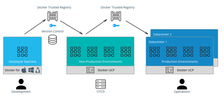
General Workflow
A typical CI/CD workflow is shown in the following diagram:
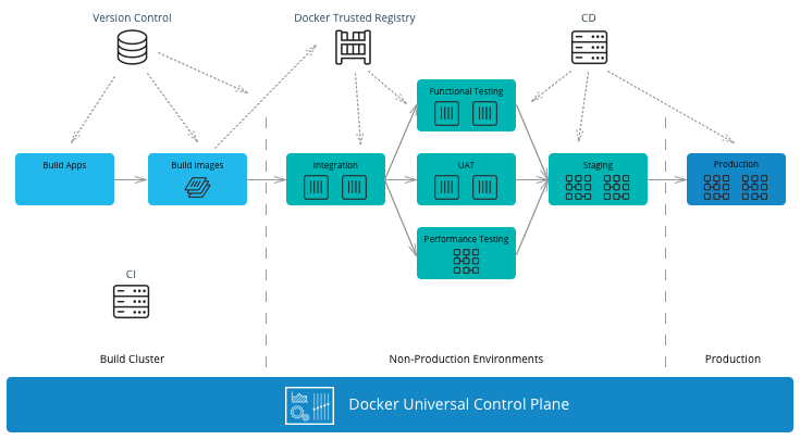
It starts on the left-hand side with development teams building applications. A CI/CD system then runs unit tests, packages the applications, and builds Docker images on the Mirantis Kubernetes Engine (MKE). If all tests pass, the images can be signed using Docker Content Trust (DCT) and shipped to Mirantis Secure Registry (MSR). The images can then be run in other non-production environments for further testing. If the images pass these testing environments, they can be signed again and then deployed by the operations team to the production environment.
MKE Clusters
It is very common to separate production and non-production workloads for any business. MKE clusters shown above is a natural fit with existing infrastructure organization and responsibilities. A production environment with higher security requirements, restrained operator access, a high-performance infrastructure, high-availability configurations, and full disaster recovery with multiple data centers. A non-production environment has different requirements with the main goal being testing and qualifying applications for production. The interface between the non-production and production clusters is MSR.
The question of whether to have a separate MKE cluster per availability zone or have one “stretched cluster” mainly depends on the network latency and bandwidth between availability zones. There could also be existing infrastructure and disaster recovery considerations to take into account.
In an enterprise environment where there can be hundreds of teams building and running applications, a best practice is to separate the build from the run resources. By doing this, the image building process does not affect the performance or availability of the running containers/services.
There are two common methods of building images using Docker EE:
- Developers build images on their own machines using Docker Desktop or Docker Desktop Enterprise(DDE) and then push them to MSR. - This is suitable if there is no CI/CD system and no dedicated build cluster. Developers have the freedom to push different images to MSR.
- A CI/CD process builds images on a build cluster and pushes them to MSR. - This is suitable if an enterprise wants to control the quality of the images pushed to MSR. Developers commit Dockerfiles to version control. They can then be analyzed and controlled for adherence to corporate standards before the CI/CD system builds the images, tests them, and pushes them to MSR. In this case, CI/CD agents should be run directly on the dedicated build nodes.
Note
In the CI/CD job, it is important to insure that images are built and pushed from the same Docker node so there is no ambiguity in the image that is pushed to MSR.
MSR Clusters
Having separate MSR clusters is very commonly used to maintain production and non-production environment segregation. A CI/CD system is used to run the unit tests, and tag the images in the non-production MSR. The images are later signed and promoted or mirrored to the Prod environment. This process gives additional control on the images stored and used in the production cluster such as Policy enforcement on image signing.
Another option is a single MSR cluster to communicate with multiple MKE clusters can also be used to enforce enterprise processes such as Security scanning in a centralized place. If pulling images from globally distributed locations takes too long then you can use the MSR Content Cache feature to create local caches. > Note: Policy enforcement on image signing will not currently work if you have your MSR in a separate cluster from MKE.
The Docker Enterprise Best Practices and Design Considerations reference architecture will guide you with the approach to deploy MKE and MSR clusters that works for your organization.
Developer Workflow
Developers and application teams usually maintain different repositories within the organization to develop, deploy, and test their applications. This section discusses the following diagram of a typical developer workflow using Docker EE as well as their interactions with the repositories:
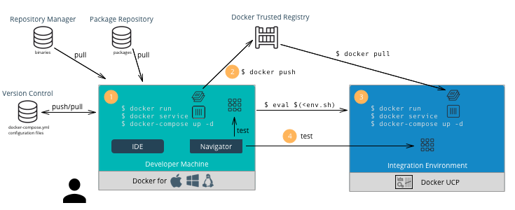
A typical developer workflow follows these steps:
- Develop Locally - On the developer’s machine with Docker Desktop
Enterprise or in a shared development environment, the developer
locally builds images, run containers, and test their containers.
There are several types of files and their respective repositories
that are used to build Docker images.
- Version Control - This is used mainly for text-based files
such as Dockerfiles,
docker-compose.yml, and configuration files. Small binaries can also kept in the same version control. Examples of version control are git, svn, Team Foundation Server, Azure DevOps, and Clear Case. - Repository Manager - These hold larger binary files such as Maven/Java, npm, NuGet, and RubyGems. Examples include Nexus, Artifactory, and Archiva.
- Package Repository - These hold packaged applications specific
to an operating system such as CentOS, Ubuntu, and Windows Server.
Examples include yum, apt-get, and PackageManagement. After
building an image, developers can run the container using the
environment variables and configuration files for their
environments. They can also run several containers together
described in a
docker-compose.ymlfile and test the application.
- Version Control - This is used mainly for text-based files
such as Dockerfiles,
- Push Images - Once an image has been tested locally, it can be
pushed to the Mirantis Secure Registry. The developer must have an
account on MSR and can push to a registry on their user account for
testing on MKE. For example:
docker push dtr.example.com/kathy.seaweed/apache2:1.0 - Deploy on MKE - The developer might want to do a test deployment
on an integration environment on MKE in the case where the
development machine does not have the ability or access to all the
resources to run the entire application. They might also want to test
whether the application scales properly if it’s deployed as a
service. In this case the developer would use CLI-based
access to
deploy the application on
MKE.
Use
$ docker context use <mke context>to point the Docker client to MKE. Then run the following command:$ docker stack deploy --compose-file <compose.yml> <stack name> - Test the Application - The developer can then test the deployed application on MKE from his machine to validate the configuration of the test environment.
- Commit to Version Control - Once the application is tested on MKE, the developer can commit the files used to create the application, its images, and its configuration to version control. This commit triggers the CI/CD workflow.
Developer Environment and Tools
Docker Desktop Enterprise provides local development, testing, and building of Docker applications on Mac and Windows. With work performed locally, developers can leverage a rapid feedback loop before pushing code or Docker images to shared servers / continuous integration infrastructure.
Docker Desktop Enterprise (DDE) takes Docker Desktop Community, formerly known as Docker for Windows and Docker for Mac, a step further with simplified enterprise application development and maintenance. With DDE, IT organizations can ensure developers are working with the same version of Docker Desktop and can easily distribute Docker Desktop to large teams using third-party endpoint management applications. With the Docker Desktop graphical user interface (GUI), developers do not have to work with lower-level Docker commands and can auto-generate Docker artifacts.
Installed with a single click or via command line, Docker Desktop Enterprise is integrated with the host OS framework, networking, and filesystem. DDE is also designed to integrate with existing development environments (IDEs) such as Visual Studio, and IntelliJ. With support for defined application templates, Docker Desktop Enterprise allows organizations to specify the look and feel of their applications.
IDE
Docker Desktop Enterprise is not a native IDE for developing application code. However, most leading IDEs (VS Code, NetBeans, Eclipse, IntelliJ, Visual Studio) have support for Docker through plugins or add-ons. Our labs contain tutorials on how to setup and use common developer tools and programming languages with Docker.
Note
Optimizing images sizes.** If an image size becomes too large, a quick way
to identify where possible optimizations are is to use the docker history
<image> command. It will tell you which lines in the Dockerfile added what
size to the image. Best practices for writing Dockerfiles
Docker Client CLI Contexts
When working with Docker EE and the Docker command line, it is important to keep in mind the context that the command is running in.
- Local Mirantis Container Runtime — This is the main context used for development of Dockerfiles and testing locally on the developer’s machine.
- Remote MKE CLI — CLI-based access is used for building and running applications on a MKE cluster.
- MKE GUI — The Docker EE web user interface provides an alternative to the CLI.
- Remote MKE Node — Sometimes it can be useful for debugging to directly connect to a node on the MKE cluster. In this case, SSH can be used, and the commands are executed on the Docker engine of the node.
A single Docker CLI can have multiple contexts. Each context contains
all of the endpoint and security information required to manage a
different cluster or node. The docker context command makes it easy
to configure these contexts and switch between them.
As an example, a single Docker client on your company laptop might be
configured with two contexts; dev-k8s and prod-swarm.
dev-k8s contains the endpoint data and security credentials to
configure and manage a Kubernetes cluster in a development environment.
prod-swarm contains everything required to manage a Swarm cluster in
a production environment. Once these contexts are configured, you can
use the top-level docker context use <context-name> to easily switch
between them. Working With
Contexts
CI/CD Workflow
A CI/CD platform uses different systems within the organization to automatically build, deploy, and test applications. This section discusses a typical CI/CD workflow using Docker EE and the interactions with those repositories as shown in the following illustration:
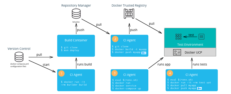
A typical CI/CD workflow follows these steps:
- Build Application — A change to the version control of the application triggers a build by the CI Agent. A build container is started and passed parameters specific to the application. The container can run on a separate Docker host or on MKE. The container obtains the source code from version control, runs the commands of the application’s build tool, and finally pushes the resulting artifact to a Repository Manager.
- Build Image — The CI Agent pulls the Dockerfile and associated files to build the image from version control. The Dockerfile is setup so that the artifact built in the previous step is copied into the image. The resulting image is pushed to MSR. If Docker Content Trust has been enabled and Notary has been installed (Notary ships within Docker Desktop Enterprise), then the image is signed with the CI/CD signature.
- Deploy Application — The CI Agent can pull a run-time
configuration from version control (e.g.
docker-compose.yml+ environment-specific configuration files) and use them to deploy the application on MKE via the CLI-based access. - Test Application — The CI Agent deploys a test container to test the application deployed in the previous step. If all of the tests pass, then the image can be signed with a QA signature by pulling and pushing the image to MSR. This push triggers the Operations workflow.
Note
The CI Agent can also be Dockerized, however, since it runs Docker commands, it needs access to the host’s Mirantis Container Runtime. This can be done by mounting the host’s Docker socket, for example:
$ docker run --rm -it --name ciagent \
   -v /var/run/docker.sock:/var/run/docker.sock \
   ciagent:1
CI/CD Environment and Tools
The nodes of the CI/CD environment where Docker is used to build applications or images should have Mirantis Container Runtime installed. The nodes can be labeled “build” to create a separate cluster.
There are many CI/CD software systems available (Jenkins, Visual Studio, TeamCity, etc). Most of the leading systems have support for Docker through plugins or add-ons. However, to ensure the most flexibility in creating CI/CD workflows, it is recommended that you use the native Docker CLI or rest API for building images or deploying containers/services.
Operations Workflow
The Operations workflow usually consists of two parts. It starts at the beginning of the entire development pipeline creating base images for development teams to use, and it ends with pulling and deploying the production ready images from the developer teams. The workflow for creating base images is the same as the developer workflow, so it is not shown here. However, the following diagram illustrates a typical Operations workflow for deploying images in production:
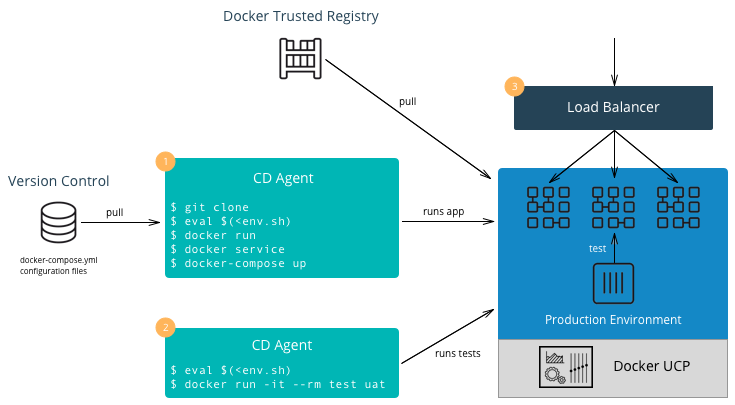
A typical Operations workflow follows these steps:
- Deploy Application — The deployment to production can be
triggered automatically via a change to version control for the
application or it can be triggered by operations. It can also be
executed manually or done by a CI/CD agent. A tag of the deployment
configuration files specific to the production environment is pulled
from version control. This includes a
docker-composefile or scripts which deploy the services as well as configuration files. Secrets such as passwords or certificates that are specific to production environments should be added or updated. Starting with Docker 17.03 (and Docker Engine 1.13), Docker has native secrets management. The CD Agent can then deploy the production topology in MKE. - Test Application — The CD Agent deploys a test container to test the application deployed in the previous step. If all of the tests pass, then the application is ready to handle production load.
- Balance the Load — Depending on the deployment pattern (Big Bang, Rolling, Canary, Blue Green, etc.), an external load balancer, DNS server, or router is reconfigured to send all or part of the requests to the newly deployed application. The older version of the application can remain deployed in case of the need to rollback. Once the new application is deemed stable, the older version can be removed.
Enterprise Base Images
The Operations team will usually build and maintain “base images.” They
typically contain the OS, middleware, and tooling to enforce enterprise
policies. They might also contain any enterprise credentials used to
access repositories or license servers. The enterprise base images are
then pushed to MSR scanned, remediated, and then offered for
consumption. The development teams can then inherit from the enterprise
base images by using the keyword FROM in their Dockerfile
referencing the base image in the enterprise MSR and then adding their
application specific components, applications, and configuration to
their own application images.
Note
Squash function. Since the base images do not change that often and are
widely used within an organization, minimizing their size is very important.
You can use docker build --squash -t <image> . to create only one layer
and optimize the size of the image. You will lose the ability to modify,
so this is recommended for base images and not necessarily for application
images which change often.
Summary
This document discussed the Docker development pipeline, integration with existing systems, and also covers the specific developer, CI/CD, and operations workflows and environments. Follow these best practices to create an effective enterprise development pipeline.