MCP Deployment Guide Q4`18 documentation
MCP Deployment Guide
This guide provides instructions for deploying Mirantis Cloud Platform (MCP) and is intended for Mirantis deployment and QA engineers.
Preface
This documentation provides information on how to use Mirantis products to deploy cloud environments. The information is for reference purposes and is subject to change.
Intended audience
This documentation is intended for deployment engineers, system administrators, and developers; it assumes that the reader is already familiar with network and cloud concepts.
Documentation history
The following table lists the released revisions of this documentation:
| Revision date | Description |
|---|---|
| February 8, 2019 | Q4`18 GA |
Introduction
MCP enables you to deploy and manage cloud platforms and their dependencies. These include OpenStack and Kubernetes based clusters.
The deployment can be performed automatically through MCP DriveTrain or using the manual deployment procedures.
The MCP DriveTrain deployment approach is based on the bootstrap automation of the Salt Master node that contains MAAS hardware nodes provisioner as well as on the automation of an MCP cluster deployment using the Jenkins pipelines. This approach significantly reduces your time and eliminates possible human errors.
The manual deployment approach provides the ability to deploy all the components of the cloud solution in a very granular fashion.
The guide also covers the deployment procedures for additional MCP components including OpenContrail, Ceph, StackLight, NFV features.
See also
Plan the deployment
The configuration of your MCP installation depends on the individual requirements that should be met by the cloud environments.
The detailed plan of any MCP deployment is determined on a per-cloud basis. For the MCP reference architecture and design overview, see: MCP Reference Architecture: Plan an OpenStack environment or MCP Reference Architecture: Plan a Kubernetes cluster depending on the type of your deployment.
Caution
Kubernetes support termination notice
Starting with the MCP 2019.2.5 update, the Kubernetes component is no longer supported as a part of the MCP product. This implies that Kubernetes is not tested and not shipped as an MCP component. Although the Kubernetes Salt formula is available in the community driven SaltStack formulas ecosystem, Mirantis takes no responsibility for its maintenance.
Customers looking for a Kubernetes distribution and Kubernetes lifecycle management tools are encouraged to evaluate the Mirantis Kubernetes-as-a-Service (KaaS) and Docker Enterprise products.
At the same time, MCP provides a flexible reduced prebuilt mirror image that you can customize depending on the needs of your MCP deployment after the initial bootstrap is performed. The usage of the prebuilt mirror image is essential in case of an offline MCP deployment scenario. The prebuilt mirror image contains the Debian package mirror (Aptly or flat deb repositories), Docker images mirror (Registry), Git repositories mirror, and mirror of the Mirantis Ubuntu VM cloud images (VCP). This guide includes the steps required for the case with the additional prebuilt VM deployment on the Foundation node.
Prepare for the deployment
Create a project repository
An MCP cluster deployment configuration is stored in a Git repository created on a per-customer basis. This section instructs you on how to manually create and prepare your project repository for an MCP deployment.
Before you start this procedure, create a Git repository in your version control system, such as GitHub.
To create a project repository manually:
Log in to any computer.
Create an empty directory and change to that directory. In the example below, it is
mcpdoc.Initialize your project repository:
git initExample of system response:
Initialized empty Git repository in /Users/crh/Dev/mcpdoc/.git/
Add your repository to the directory you have created:
git remote add origin <YOUR-GIT-REPO-URL>
Verify that Git and your local repository are set up correctly by creating and pushing a test file to your project repository. Run the following example commands:
Note
The example commands below require the Git and GitHub credentials to be created and configured for your project repository.
git remote add origin https://github.com/example_account/mcpdoc.git
git config --local user.email "example@example.com"
git config --local user.name "example_gituser"
git config -l

echo "#. mcpdoc" >> README.md
git add README.md
git commit -m "first commit"
git push -u origin master
Create the following directories for your deployment metadata model:
mkdir -p classes/cluster
mkdir nodes
Add the Reclass variable to your bash profile by verifying your current directory using pwd and adding the string that exports the Reclass variable with the output value of the pwd command:
pwd
vim ~/.bash_profile
export RECLASS_REPO=<PATH_TO_YOUR_DEV_DIRECTORY>
Example of system response:
/Users/crh/Dev/mcpdoc/

"~/.bash_profile" 13L, 450C
export RECLASS_REPO="/Users/crh/Dev/mcpdoc/"
Log out and log back in.
Verify that your
~/.bash_profileis sourced:echo $RECLASS_REPO
The command must show the value of your
RECLASS_REPOvariable.Example of system response:
/Users/crh/Dev/mcpdoc/
Add the Mirantis Reclass module to your repository as a submodule:
git submodule add https://github.com/Mirantis/reclass-system-salt-model ./classes/system/
Example of system response:
Cloning into '<PATH_TO_YOUR_DEV_DIRECTORY>/classes/system'...
remote: Counting objects: 8923, done.
remote: Compressing objects: 100% (214/214), done.
remote: Total 8923 (delta 126), reused 229 (delta 82), pack-reused 8613
Receiving objects: 100% (8923/8923), 1.15 MiB | 826.00 KiB/s, done.
Resolving deltas: 100% (4482/4482), done.
Checking connectivity... done.
Update the submodule:
git submodule sync
git submodule update --init --recursive --remote
Add your changes to a new commit:
git add -A
Commit your changes:
git commitAdd your commit message.
Example of system response:
[master (root-commit) 9466ada] Initial Commit
 2 files changed, 4 insertions(+)
 create mode 100644 .gitmodules
 create mode 160000 classes/system
Push your changes:
git pushProceed to Create a deployment metadata model.
Create a deployment metadata model
In a Reclass metadata infrastructural model, the data is stored as a set of several layers of objects, where objects of a higher layer are combined with objects of a lower layer, that allows for as flexible configuration as required.
The MCP metadata model has the following levels:
- Service level includes metadata fragments for individual services that are stored in Salt formulas and can be reused in multiple contexts.
- System level includes sets of services combined in a such way that the installation of these services results in a ready-to-use system.
- Cluster level is a set of models that combine already created system objects into different solutions. The cluster module settings override any settings of service and system levels and are specific for each deployment.
The model layers are firmly isolated from each other. They can be aggregated on a south-north direction using service interface agreements for objects on the same level. Such approach allows reusing of the already created objects both on service and system levels.
This section describes how to generate the cluster level metadata model for your MCP cluster deployment using the Model Designer web UI. The tool used to generate the model is Cookiecutter, a command-line utility that creates projects from templates.
While generating a metadata model, you can enable automated encryption
of all secrets for the Salt Master node .iso file.
Note
The Model Designer web UI is only available within Mirantis. The Mirantis deployment engineers can access the Model Designer web UI using their Mirantis corporate username and password.
The workflow of a model creation includes the following stages:
Defining the model through the Model Designer web UI.
Optional. Tracking the execution of the model creation pipeline in the Jenkins web UI.
Obtaining the generated model to your email address or getting it published to the project repository directly.
Note
If you prefer publishing to the project repository, verify that the dedicated repository is configured correctly and Jenkins can access it. See Create a project repository for details.
As a result, you get a generated deployment model and can customize it to fit specific use-cases. Otherwise, you can proceed with the base infrastructure deployment.
Enable all secrets encryption
The Model Designer UI supports passing a private key
to enable automated encryption of secrets.yml during the Salt Master node
.iso file generation.
To enable all secrets encryption in the Model Designer UI:
Generate a private PGP key locally. For example:
mkdir -p ~/mcp-temp-gpg-key ; cd ~/mcp-temp-gpg-key
cd cat <<EOF > gpg-batch.txt
Key-Type: 1
Key-Length: 4096
Expire-Date: 0
Name-Real: gpg-demo.com
Name-Email: saltmasterdemo@example.com
EOF
export GNUPGHOME="$(pwd)/gpghome" ; mkdir -p gpghome ; chmod 0700 gpghome
gpg --gen-key --batch < gpg-batch.txt
gpg --export-secret-key -a saltmasterdemo@example.com > gpgkey.asc
gpg --list-secret-keys
Copy the generated private PGP key:
cat gpgkey.ascExample of system response:
-----BEGIN PGP PRIVATE KEY BLOCK-----
Version: GnuPG v1

lQcYBFyKM7kBEADGU6P/Lp9YRMY/vLw7VOF5Sox1rnu2lz6YqnNQ2J+ZHVlPA9R
........
Proceed with the metadata model generation as described in Define the deployment model. While generating the metadata model, enable the following parameters:
- In General -> Services section, select Secrets Encryption Enabled
- In Infra -> Salt Master section, paste the private key to the Secrets Encryption Private Key field
Proceed to the metadata model generation.
Define the deployment model
This section instructs you on how to define the cluster level metadata model through the web UI using Cookiecutter. Eventually, you will obtain a generic deployment configuration that can be overriden afterwards.
Note
The Model Designer web UI is only available within Mirantis. The Mirantis deployment engineers can access the Model Designer web UI using their Mirantis corporate username and password.
Note
Currently, Cookiecutter can generate models with basic configurations. You may need to manually customize your model after generation to meet specific requirements of your deployment, for example, four interfaces bonding.
To define the deployment model:
- Log in to the web UI.
- Go to Integration dashboard > Models > Model Designer.
- Click Create Model. The Create Model page opens.
- Configure your model by selecting a corresponding tab and editing as
required:
- Configure General deployment parameters. Click Next.
- Configure Infrastructure related parameters. Click Next.
- Configure Product related parameters. Click Next.
- Verify the model on the Output summary tab. Edit if required.
- Click Confirm to trigger the
Generate reclass cluster
separated-products-auto
Jenkins pipeline. If required, you can track the success of the pipeline execution in the Jenkins web UI.
If you selected the Send to e-mail address publication option on the General parameters tab, you will receive the generated model to the e-mail address you specified in the Publication options > Email address field on the Infrastructure parameters tab. Otherwise, the model will automatically be pushed to your project repository.
General deployment parameters
The tables in this section outline the general configuration parameters that you can define for your deployment model through the Model Designer web UI. Consult the Define the deployment model section for the complete procedure.
The General deployment parameters wizard includes the following sections:
- Basic deployment parameters cover basic deployment parameters
- Services deployment parameters define the platform you need to generate the model for
- Networking deployment parameters cover the generic networking setup for a dedicated management interface and two interfaces for the workload. The two interfaces for the workload are in bond and have tagged sub-interfaces for the Control plane (Control network/VLAN) and Data plane (Tenant network/VLAN) traffic. The PXE interface is not managed and is leaved to default DHCP from installation. Setups for the NFV scenarios are not covered and require manual configuration.
| Parameter | Default JSON output | Description |
|---|---|---|
| Cluster name | cluster_name: deployment_name |
The name of the cluster that will be used as cluster/<cluster_name>/
in the project directory structure |
| Cluster domain | cluster_domain: deploy-name.local |
The name of the domain that will be used as part of the cluster FQDN |
| Public host | public_host: ${_param:openstack_proxy_address} |
The name or IP address of the public endpoint for the deployment |
| Reclass repository | reclass_repository: https://github.com/Mirantis/mk-lab-salt-model.git |
The URL to your project Git repository containing your models |
| Cookiecutter template URL | cookiecutter_template_url: git@github.com:Mirantis/mk2x-cookiecutter-reclass-model.git |
The URL to the Cookiecutter template repository |
| Cookiecutter template branch | cookiecutter_template_branch: master |
The branch of the Cookiecutter template repository to use, master
by default. Use refs/tags/<mcp_version> to generate the model that
corresponds to a specific MCP release version. For example, 2017.12.
Other possible values include stable and testing. |
| Shared Reclass URL | shared_reclass_url: ssh://mcp-jenkins@gerrit.mcp.mirantis.net:29418/salt-models/reclass-system.git |
The URL to the shared system model to be used as a Git submodule for the MCP cluster |
| MCP version | mcp_version: stable |
Version of MCP to use, stable by default. Enter the release version
number, for example, 2017.12. Other possible values are:
nightly, testing. For nightly, use
cookiecutter_template_branch: master. |
| Cookiecutter template credentials | cookiecutter_template_credentials: gerrit |
Credentials to Gerrit to fetch the Cookiecutter templates repository. The parameter is used by Jenkins |
| Deployment type | deployment_type: physical |
The supported deployment types include:
|
| Publication method | publication_method: email |
The method to obtain the template. Available options include:
|
| Parameter | Default JSON output | Description |
|---|---|---|
| Platform |
|
The platform to generate the model for:
|
| StackLight enabled | stacklight_enabled: 'True' |
Enables a StackLight LMA sub-cluster. |
| Gainsight service enabled | gainsight_service_enabled: 'False' |
Enables support for the Salesforce/Gainsight service |
| Salesforce notifications enabled | sf_notifications_enabled: 'False' |
Enables sending of Alertmanager notifications to Salesforce |
| Ceph enabled | ceph_enabled: 'True' |
Enables a Ceph sub-cluster. |
| CI/CD enabled | cicd_enabled: 'True' |
Enables a CI/CD sub-cluster. |
| OSS enabled | oss_enabled: 'True' |
Enables an OSS sub-cluster. |
| Benchmark node enabled | bmk_enabled: 'False' |
Enables a benchmark node. False, by default. |
| Barbican enabled | barbican_enabled: 'False' |
Enables the Barbican service |
| Backend for Barbican | barbican_backend: dogtag |
The backend for Barbican |
| Parameter | Default JSON output | Description |
|---|---|---|
| DNS Server 01 | dns_server01: 8.8.8.8 |
The IP address of the dns01 server |
| DNS Server 02 | dns_server02: 1.1.1.1 |
The IP address of the dns02 server |
| Deploy network subnet | deploy_network_subnet: 10.0.0.0/24 |
The IP address of the deploy network with the network mask |
| Deploy network gateway | deploy_network_gateway: 10.0.0.1 |
The IP gateway address of the deploy network |
| Control network subnet | control_network_subnet: 10.0.1.0/24 |
The IP address of the control network with the network mask |
| Tenant network subnet | tenant_network_subnet: 10.0.2.0/24 |
The IP address of the tenant network with the network mask |
| Tenant network gateway | tenant_network_gateway: 10.0.2.1 |
The IP gateway address of the tenant network |
| Control VLAN | control_vlan: '10' |
The Control plane VLAN ID |
| Tenant VLAN | tenant_vlan: '20' |
The Data plane VLAN ID |
| NTP servers Added since 2019.2.6 update | 0.pool.ntp.org,1.pool.ntp.org |
The comma-separated list of Network Time Protocol (NTP)
servers. You can also configure multiple NTP servers as required,
for example, server1.ntp.org,server2.ntp.org,server3.ntp.org. |
Publish the deployment model to a project repository
If you selected the option to receive the generated deployment model to your email address and customized it as required, you need to apply the model to the project repository.
To publish the metadata model, push the changes to the project Git repository:
git add *
git commit –m "Initial commit"

git pull -r
git push --set-upstream origin master
See also
Deploy MCP DriveTrain
To reduce the deployment time and eliminate possible human errors, Mirantis recommends that you use the semi-automated approach to the MCP DriveTrain deployment as described in this section.
Caution
The execution of the CLI commands used in the MCP Deployment
Guide requires root privileges. Therefore, unless explicitly
stated otherwise, run the commands as a root user or use
sudo.
The deployment of MCP DriveTrain bases on the bootstrap automation of the Salt Master node. On a Reclass model creation, you receive the configuration drives by the email that you specified during the deployment model generation.
Depending on the deployment type, you receive the following configuration drives:
- For an online and offline deployment, the configuration drive for the
cfg01VM that is used in cloud-init to set up a virtual machine with Salt Master, MAAS provisioner, Jenkins server, and local Git server installed on it. - For an offline deployment, the configuration drive for the APT VM that is used in cloud-init to set up a virtual machine with all required repositories mirrors.
| # | Description |
|---|---|
| 1 | Manually deploy and configure the Foundation node as described in Prerequisites for MCP DriveTrain deployment. |
| 2 | Create the deployment model using the Model Designer web UI as described in Create a deployment metadata model. |
| 3 | Obtain the pre-built ISO configuration drive(s) with the Reclass deployment metadata model to you email. If required, customize and regenerate the configuration drives as described in Generate configuration drives manually. |
| 4 | Bootstrap the APT node. Optional, for an offline deployment only. For details, see: Deploy the APT node. |
| 5 | Bootstrap the Salt Master node that contains MAAS provisioner, Jenkins server, and local Git server. For details, see: Deploy the Salt Master node. |
| 6 | Deploy the remaining bare metal servers using the MAAS provisioner. For details, see: Provision physical nodes using MAAS and Deploy physical nodes. |
| 7 | Deploy MCP CI/CD using Jenkins as described in Deploy CI/CD. |
Prerequisites for MCP DriveTrain deployment
Before you proceed with the actual deployment, verify that you have performed the following steps:
Deploy the Foundation physical node using one of the initial versions of Ubuntu Xenial, for example, 16.04.1.
Use any standalone hardware node where you can run a KVM-based
day01virtual machine with an access to the deploy/control network. The Foundation node will host the Salt Master node that also includes the MAAS provisioner by default. For the offline case deployment, the Foundation node will also host the mirror VM.Depending on your case, proceed with one of the following options:
If you do not have a deployment metadata model:
Create a model using the Model Designer UI as described in Create a deployment metadata model.
Note
For an offline deployment, select the Offline deployment and Local repositories options under the Repositories section on the Infrastructure parameters tab.
Customize the obtained configuration drives as described in Generate configuration drives manually. For example, enable custom user access.
If you use an already existing model that does not have configuration drives, or you want to generate updated configuration drives, proceed with Generate configuration drives manually.
Configure the following bridges on the Foundation node:
br-mgmfor the management network andbr-ctlfor the control network.Log in to the Foundation node through IPMI.
Note
If the IPMI network is not reachable from the management or control network, add the
br-ipmibridge for the IPMI network or any other network that is routed to the IPMI network.Create PXE bridges to provision network on the foundation node:
brctl addbr br-mgm
brctl addbr br-ctl
Install the
br-ctlutility:apt install bridge-utils
Add the bridges definition for
br-mgmandbr-ctlto/etc/network/interfaces. Use definitions from your deployment metadata model.Example:
auto br-mgm
iface br-mgm inet static
        address 172.17.17.200
        netmask 255.255.255.192
        bridge_ports bond0
Restart networking from the IPMI console to bring the bonds up.
Verify that the foundation node bridges are up by checking the output of the ip a show command:
ip a show br-ctl
Example of system response:
8: br-ctl: <BROADCAST,MULTICAST,UP,LOWER_UP> mtu 1500 qdisc noqueue state UP group default qlen 1000
    link/ether 00:1b:21:93:c7:c8 brd ff:ff:ff:ff:ff:ff
    inet 172.17.45.241/24 brd 172.17.45.255 scope global br-ctl
       valid_lft forever preferred_lft forever
    inet6 fe80::21b:21ff:fe93:c7c8/64 scope link
       valid_lft forever preferred_lft forever
Depending on your case, proceed with one of the following options:
- If you perform an online deployment, proceed to Deploy the Salt Master node.
- If you perform the offline deployment or online deployment with local mirrors, proceed to Deploy the APT node.
Deploy the APT node
MCP enables you to deploy the whole MCP cluster without access to the
Internet. On creating the metadata model, along with the configuration drive
for the cfg01 VM, you will obtain a preconfigured QCOW2 image that will
contain packages, Docker images, operating system images, Git repositories,
and other software required specifically for the offline deployment.
This section describes how to deploy the apt01 VM using the
prebuilt configuration drive.
Warning
Perform the procedure below only in case of an offline deployment or when using a local mirror from the prebuilt image.
To deploy the APT node:
Verify that you completed steps described in Prerequisites for MCP DriveTrain deployment.
Log in to the Foundation node.
Note
Root privileges are required for following steps. Execute the commands as a root user or use
sudo.Download the latest version of the prebuilt
http://images.mirantis.com/mcp-offline-image-<BUILD-ID>.qcow2image for theaptnode from http://images.mirantis.com.In the
/var/lib/libvirt/images/directory, create anapt01/subdirectory where the offline mirror image will be stored:Note
You can create and use a different subdirectory in
/var/lib/libvirt/images/. If that is the case, verify that you specify the correct directory for theVM_*DISKvariables described in next steps.mkdir -p /var/lib/libvirt/images/apt01/
Save the image on the Foundation node as
/var/lib/libvirt/images/apt01/system.qcow2.Copy the configuration ISO drive for the APT VM provided with the metadata model for the offline image to, for example,
/var/lib/libvirt/images/apt01/.Caution
By default, the prebuilt image does not have a possibility to log in to.
Note
If you are using an already existing model that does not have configuration drives, or you want to generate updated configuration drives, for example, with an unlocked
rootlogin for debugging purposes, proceed with Generate configuration drives manually.cp /path/to/prepared-drive/apt01-config.iso /var/lib/libvirt/images/apt01/apt01-config.iso
Deploy the APT node:
Download the shell script from GitHub:
export MCP_VERSION="master"
wget https://raw.githubusercontent.com/Mirantis/mcp-common-scripts/${MCP_VERSION}/predefine-vm/define-vm.sh
Make the script executable, export the required variables:
chmod +x define-vm.sh
export VM_NAME="apt01.<CLUSTER_DOMAIN>"
export VM_SOURCE_DISK="/var/lib/libvirt/images/apt01/system.qcow2"
export VM_CONFIG_DISK="/var/lib/libvirt/images/apt01/apt01-config.iso"
The
CLUSTER_DOMAINvalue is the cluster domain name used for the model. See Basic deployment parameters for details.Note
You may add other optional variables that have default values and change them depending on your deployment configuration. These variables include:
VM_MGM_BRIDGE_NAME="br-mgm"VM_CTL_BRIDGE_NAME="br-ctl"VM_MEM_KB="12589056"VM_CPUS="4"
The recommended
VM_MEM_KBfor the Salt Master node is12589056(or more depending on your cluster size) that is 12 GB of RAM. For large clusters, you should also increaseVM_CPUS.The recommended
VM_MEM_KBfor the local mirror node is8388608(or more) that is 8 GB of RAM.The
br-mgmandbr-ctlvalues are the names of the Linux bridges. See Prerequisites for MCP DriveTrain deployment for details. Custom names can be passed to a VM definition using theVM_MGM_BRIDGE_NAMEandVM_CTL_BRIDGE_NAMEvariables accordingly.Run the shell script:
./define-vm.sh
Start the
apt01VM:virsh start apt01.<CLUSTER_DOMAIN>
For MCP versions prior to the 2019.2.14 maintenance update, perform the following additional steps:
SSH to the
apt01node.Verify the certificate:
openssl x509 -checkend 1 -in /var/lib/docker/swarm/certificates/swarm-node.crt
If the certificate has expired, restart Docker Swarm to regenerate it:
systemctl stop docker || true
rm -rf /var/lib/docker/swarm/*
systemctl restart docker
sleep 5
docker ps
docker swarm init --advertise-addr 127.0.0.1
sleep 5
cd /etc/docker/compose/docker/
docker stack deploy --compose-file docker-compose.yml docker
sleep 5
cd /etc/docker/compose/aptly/
docker stack deploy --compose-file docker-compose.yml aptly
sleep 5
docker ps
After completing the steps above, you obtain the apt01 node that contains
only the pre-built content. Now, you can proceed with
Deploy the Salt Master node. Once you deploy the Salt Master node,
you will be able to customize the content of the local mirror, as described in
Customize the prebuilt mirror node.
Deploy the Salt Master node
The Salt Master node acts as a central control point for the clients that are called Salt minion nodes. The minions, in their turn, connect back to the Salt Master node.
This section describes how to set up a virtual machine with Salt Master, MAAS provisioner, Jenkins server, and local Git server. The procedure is applicable to both online and offline MCP deployments.
To deploy the Salt Master node:
Log in to the Foundation node.
Note
Root privileges are required for following steps. Execute the commands as a root user or use
sudo.In case of an offline deployment, replace the content of the
/etc/apt/sources.listfile with the following lines:deb [arch=amd64] http://<local_mirror_url>/ubuntu xenial-security main universe restricted deb [arch=amd64] http://<local_mirror_url>/ubuntu xenial-updates main universe restricted deb [arch=amd64] http://<local_mirror_url>/ubuntu xenial main universe restricted
Create a directory for the VM system disk:
Note
You can create and use a different subdirectory in
/var/lib/libvirt/images/. If that is the case, verify that you specify the correct directory for theVM_*DISKvariables described in next steps.mkdir -p /var/lib/libvirt/images/cfg01/
Download the
day01image for thecfg01node:wget http://images.mirantis.com/cfg01-day01-<BUILD_ID>.qcow2 -O \ /var/lib/libvirt/images/cfg01/system.qcow2
Substitute
<BUILD_ID>with the required MCP Build ID, for example,2019.2.0.Copy the configuration ISO drive for the
cfg01VM provided with the metadata model for the offline image to, for example,/var/lib/libvirt/images/cfg01/cfg01-config.iso.Note
If you are using an already existing model that does not have configuration drives, or you want to generate updated configuration drives, for example, with an unlocked
rootlogin for debugging purposes, proceed with Generate configuration drives manually.Caution
Make sure to securely back up the configuration ISO drive image. This image contains critical information required to re-install your
cfg01node in case of storage failure, including master key for all encrypted secrets in the cluster metadata model.Failure to back up the configuration ISO image may result in loss of ability to manage MCP in certain hardware failure scenarios.
cp /path/to/prepared-drive/cfg01-config.iso /var/lib/libvirt/images/cfg01/cfg01-config.iso
Create the Salt Master VM domain definition using the example script:
Download the shell scripts from GitHub with the required MCP release version. For example:
export MCP_VERSION="2019.2.0"
git clone https://github.com/Mirantis/mcp-common-scripts -b release/${MCP_VERSION}
Make the script executable and export the required variables:
cd mcp-common-scripts/predefine-vm/
export VM_NAME="cfg01.[CLUSTER_DOMAIN]"
export VM_SOURCE_DISK="/var/lib/libvirt/images/cfg01/system.qcow2"
export VM_CONFIG_DISK="/var/lib/libvirt/images/cfg01/cfg01-config.iso"
The
CLUSTER_DOMAINvalue is the cluster domain name used for the model. See Basic deployment parameters for details.Note
You may add other optional variables that have default values and change them depending on your deployment configuration. These variables include:
VM_MGM_BRIDGE_NAME="br-mgm"VM_CTL_BRIDGE_NAME="br-ctl"VM_MEM_KB="12589056"VM_CPUS="4"
The recommended
VM_MEM_KBfor the Salt Master node is12589056(or more depending on your cluster size) that is 12 GB of RAM. For large clusters, you should also increaseVM_CPUS.The recommended
VM_MEM_KBfor the local mirror node is8388608(or more) that is 8 GB of RAM.The
br-mgmandbr-ctlvalues are the names of the Linux bridges. See Prerequisites for MCP DriveTrain deployment for details. Custom names can be passed to a VM definition using theVM_MGM_BRIDGE_NAMEandVM_CTL_BRIDGE_NAMEvariables accordingly.Run the shell script:
./define-vm.sh
Start the Salt Master node VM:
virsh start cfg01.[CLUSTER_DOMAIN]
Log in to the Salt Master virsh console with the user name and password that you created in step 4 of the Generate configuration drives manually procedure:
virsh console cfg01.[CLUSTER_DOMAIN]
If you use local repositories, verify that
mk-pipelinesare present in/home/repo/mkandpipeline-libraryis present in/home/repo/mcp-ciaftercloud-initfinishes. If not, fix the connection to local repositories and run the/var/lib/cloud/instance/scripts/part-001script.Verify that the following states are successfully applied during the execution of
cloud-init:salt-call state.sls linux.system,linux,openssh,salt salt-call state.sls maas.cluster,maas.region,reclass
Otherwise, fix the pillar and re-apply the above states.
In case of using
kvm01as the Foundation node, perform the following steps on it:Depending on the deployment type, proceed with one of the options below:
For an online deployment, add the following
debrepository to/etc/apt/sources.list.d/mcp_saltstack.list:deb [arch=amd64] https://mirror.mirantis.com/<MCP_VERSION>/saltstack-2017.7/xenial/ xenial main
For an offline deployment or local mirrors case, in
/etc/apt/sources.list.d/mcp_saltstack.list, add the followingdebrepository:deb [arch=amd64] http://<local_mirror_url>/<MCP_VERSION>/saltstack-2017.7/xenial/ xenial main
Install the
salt-minionpackage.Modify
/etc/salt/minion.d/minion.conf:id: <kvm01_FQDN> master: <Salt_Master_IP_or_FQDN>
Restart the
salt-minionservice:service salt-minion restart
Check the output of
salt-keycommand on the Salt Master node to verify that the minion ID ofkvm01is present.
Verify the Salt infrastructure
Before you proceed with the deployment, validate the Reclass model and node pillars.
To verify the Salt infrastructure:
Log in to the Salt Master node.
Verify the Salt Master pillars:
reclass -n cfg01.<cluster_domain>The
cluster_domainvalue is the cluster domain name that you created while preparing your deployment metadata model. See Basic deployment parameters for details.Verify that the Salt version for the Salt minions is the same as for the Salt Master node, that is currently
2017.7:salt-call --version salt '*' test.version
If required, enable management of the offline mirror VM (
apt01) and customize the VM contents as described in Enable the management of the APT node through the Salt Master node.
Enable the management of the APT node through the Salt Master node
In compliance with the security best practices, MCP enables you to connect your offline mirror APT VM to the Salt Master node and manage it as any infrastructure VM on your MCP deployment.
Note
This section is only applicable for the offline deployments where
all repositories are stored on a specific VM deployed using
the MCP apt01 offline image, which is included in the MCP
release artifacts.
For the deployments managed by the MCP 2018.8.0 Build ID or later, you should not manually enable the Salt minion on the offline image VM as it is configured automatically on boot during the APT VM provisioning.
Though, if your want to enable the management of the offline image VM through the Salt Master node on an existing deployment managed by the MCP version below the 2018.8.0 Build ID, you need to perform the procedure included in this section.
To enable the Salt minion on an existing offline mirror node:
Connect to the serial console of your offline image VM, which is included in the pre-built offline APT QCOW image:
virsh console $(virsh list --all --name | grep ^apt01) --force
Log in with the user name and password that you created in step 4 of the Generate configuration drives manually procedure.
Example of system response:
Connected to domain apt01.example.local
Escape character is ^]
Press Enter to drop into the root shell.
Configure the Salt minion and start it:
echo "" > /etc/salt/minion
echo "master: <IP_address>" > /etc/salt/minion.d/minion.conf
echo "id: <apt01.example.local>" >> /etc/salt/minion.d/minion.conf
service salt-minion stop
rm -f /etc/salt/pki/minion/*
service salt-minion start
Quit the serial console by sending the Ctrl + ] combination.
Log in to the Salt Master node.
Verify that you have the offline mirror VM Salt minion connected to your Salt Master node:
salt-key -L | grep apt
The system response should include your offline mirror VM domain name. For example:
apt01.example.local
Verify that you can access the Salt minion from the Salt Master node:
salt apt01\* test.ping
Verify the Salt states are mapped to the offline mirror VM:
salt apt01\* state.show_top
Now, you can manage your offline mirror APT VM from the Salt Master node. At this point, the Salt Master node does not manage the offline mirror content. If you need to adjust the content of your offline mirror, refer to Customize the prebuilt mirror node.
Configure MAAS for bare metal provisioning
Before you proceed with provisioning of the remaining bare metal nodes, configure MAAS as described below.
To configure MAAS for bare metal provisioning:
Log in to the MAAS web UI through
http://<infra_config_deploy_address>:5240/MAASwith the following credentials:- Username:
mirantis - Password:
r00tme
- Username:
Go to the Subnets tab.
Select the fabric that is under the deploy network.
In the VLANs on this fabric area, click the VLAN under the VLAN column where the deploy network subnet is.
In the Take action drop-down menu, select Provide DHCP.
Adjust the IP range as required.
Note
The number of IP addresses should not be less than the number of the planned VCP nodes.
Click Provide DHCP to submit.
If you use local package mirrors:
Note
The following steps are required only to specify the local Ubuntu package repositories that are secured by a custom GPG key and used mainly for the offline mirror images prior the MCP version 2017.12.
- Go to Settings > Package repositories.
- Click Actions > Edit on the Ubuntu archive repository.
- Specify the GPG key of the repository in the Key field.
The key can be obtained from the
aptly_gpg_public_keyparameter in the cluster level Reclass model. - Click Save.
Provision physical nodes using MAAS
Physical nodes host the Virtualized Control Plane (VCP) of your Mirantis Cloud Platform deployment.
This section describes how to provision the physical nodes using the MAAS service that you have deployed on the Foundation node while deploying the Salt Master node.
The servers that you must deploy include at least:
- For OpenStack:
kvm02andkvm03infrastructure nodescmp0compute node
- For Kubernetes:
kvm02andkvm03infrastructure nodesctl01,ctl02,ctl03controller nodescmp01andcmp02compute nodes
You can provision physical nodes automatically or manually:
- An automated provisioning requires you to define IPMI and MAC addresses in your Reclass model. After you enforce all servers, the Salt Master node commissions and provisions them automatically.
- A manual provisioning enables commissioning nodes through the MAAS web UI.
Before you proceed with the physical nodes provisioning, you may want to customize the commissioning script, for example, to set custom NIC names. For details, see: Add custom commissioning scripts.
Warning
Before you proceed with the physical nodes provisioning, verify that BIOS settings enable PXE booting from NICs on each physical server.
Automatically commission and provision the physical nodes
This section describes how to define physical nodes in a Reclass model to automatically commission and then provision the nodes through Salt.
Automatically commission the physical nodes
You must define all IPMI credentials in your Reclass model to access physical servers for automated commissioning. Once you define the nodes, Salt enforces them into MAAS and starts commissioning.
To automatically commission physical nodes:
Define all physical nodes under
classes/cluster/<cluster>/infra/maas.ymlusing the following structure.For example, to define the
kvm02node:maas: region: machines: kvm02: interface: mac: 00:25:90:eb:92:4a power_parameters: power_address: kvm02.ipmi.net power_password: password power_type: ipmi power_user: ipmi_user
Note
To get MAC addresses from IPMI, you can use the ipmi tool. Usage example for Supermicro:
ipmitool -U ipmi_user-P passowrd -H kvm02.ipmi.net raw 0x30 0x21 1| tail -c 18
(Optional) Define the IP address on the first (PXE) interface. By default, it is assigned automatically and can be used as is.
For example, to define the
kvm02node:maas: region: machines: kvm02: interface: mac: 00:25:90:eb:92:4a mode: "static" ip: "2.2.3.15" subnet: "subnet1" gateway: "2.2.3.2"
(Optional) Define a custom disk layout or partitioning per server in MAAS. For more information and examples on how to define it in the model, see: Add a custom disk layout per node in the MCP model.
(Optional) Modify the commissioning process as required. For more information and examples, see: Add custom commissioning scripts.
Once you have defined all physical servers in your Reclass model, enforce the nodes:
Caution
For an offline deployment, remove the
deb-srcrepositories from commissioning before enforcing the nodes, since these repositories are not present on the reduced offlineaptimage node. To remove these repositories, you can enforce MAAS to rebuildsources.list. For example:export PROFILE="mirantis" export API_KEY=$(cat /var/lib/maas/.maas_credentials) maas login ${PROFILE} http://localhost:5240/MAAS/api/2.0/ ${API_KEY} REPO_ID=$(maas $PROFILE package-repositories read | jq '.[]| select(.name=="main_archive") | .id ') maas $PROFILE package-repository update ${REPO_ID} disabled_components=multiverse maas $PROFILE package-repository update ${REPO_ID} "disabled_pockets=backports"
The default
PROFILEvariable ismirantis. You can find your deployment-specific value for this parameter inparameters:maas:region:admin:usernameof your Reclass model.For details on building a custom list of repositories, see: MAAS GitHub project.
salt-call maas.process_machinesAll nodes are automatically commissioned.
Verify the status of servers either through the MAAS web UI or using the salt call command:
salt-call maas.machines_statusThe successfully commissioned servers appear in the
readystatus.Enforce the interfaces configuration defined in the model for servers:
salt-call state.sls maas.machines.assign_ip
To protect any static IP assignment defined, for example, in the model, configure a reserved IP range in MAAS on the management subnet.
(Optional) Enforce the disk custom configuration defined in the model for servers:
salt-call state.sls maas.machines.storage
Verify that all servers have correct NIC names and configurations.
Proceed to Provision the automatically commissioned physical nodes.
Provision the automatically commissioned physical nodes
Once you successfully commission your physical nodes, you can start the provisioning.
To provision the automatically commissioned physical nodes through MAAS:
Log in to the Salt Master node.
Run the following command:
salt-call maas.deploy_machinesCheck the status of the nodes:
salt-call maas.machines_status
local:
    ----------
    machines:
        - hostname:kvm02,system_id:anc6a4,status:Deploying
    summary:
        ----------
        Deploying:
            1
When all servers have been provisioned, perform the verification of the servers` automatic registration by running the salt-key command on the Salt Master node. All nodes should be registered. For example:
salt-key
Accepted Keys:
cfg01.bud.mirantis.net
cmp001.bud.mirantis.net
cmp002.bud.mirantis.net
kvm02.bud.mirantis.net
kvm03.bud.mirantis.net
Now, proceed to Deploy physical nodes.
Manually commission and provision the physical nodes
This section describes how to discover, commission, and provision the physical nodes using the MAAS web UI.
Manually discover and commission the physical nodes
You can discover and commission your physical nodes manually using the MAAS web UI.
To discover and commission physical nodes manually:
Power on a physical node.
In the MAAS UI, verify that the server has been discovered.
On the Nodes tab, rename the discovered host accordingly. Click Save after each renaming.
In the Settings tab, configure the Commissioning release and the Default Minimum Kernel Version to Ubuntu 16.04 TLS ‘Xenial Xerus’ and Xenial (hwe-16.04), respectively.
Note
The above step ensures that the NIC naming convention uses the predictable schemas, for example,
enp130s0f0rather thaneth0.In the Deploy area, configure the Default operating system used for deployment and Default OS release used for deployment to Ubuntu and Ubuntu 16.04 LTS ‘Xenial Xerus’, respectively.
Leave the remaining parameters as defaults.
(Optional) Modify the commissioning process as required. For more information and examples, see: Add custom commissioning scripts.
Commission the node:
- From the Take Action drop-down list, select Commission.
- Define a storage schema for each node.
- On the Nodes tab, click the required node link from the list.
- Scroll down to the Available disks and partitions section.
- Select two SSDs using check marks in the left column.
- Click the radio button to make one of the disks the boot target.
- Click Create RAID to create an MD
raid1volume. - In RAID type, select
RAID 1. - In File system, select
ext4. - Set
/as Mount point. - Click Create RAID.
The Used disks and partitions section should now look as follows:
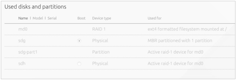
Repeat the above steps for each physical node.
Proceed to Manually provision the physical nodes.
Manually provision the physical nodes
Start the manual provisioning of the physical nodes with the control plane
kvm02 and kvm03 physical nodes, and then proceed with the compute
cmp01 node deployment.
To manually provision the physical nodes through MAAS:
- Verify that the boot order in the physical nodes’ BIOS is set in
the following order:
- PXE
- The physical disk that was chosen as the boot target in the Maas UI.
- Log in to the MAAS web UI.
- Click on a node.
- Click the Take Action drop-down menu and select Deploy.
- In the Choose your image area, verify that
Ubuntu 16.04 LTS 'Xenial Xerus'with theXenial(hwe-16.04)kernel is selected. - Click Go to deploy the node.
- Repeat the above steps for each node.
Now, proceed to Deploy physical nodes.
See also
Deploy physical nodes
After you provision physical nodes as described in Provision physical nodes using MAAS, follow the instruction below to deploy physical nodes intended for an OpenStack-based MCP cluster. If you plan to deploy a Kubernetes-based MCP cluster, proceed with steps 1-2 of the Kubernetes Prerequisites procedure.
Caution
To avoid the lack of memory for the network driver and ensure its
proper operation, specify the minimum reserved kernel memory in your Reclass
model on the cluster level for a particular hardware node. For example, use
/cluster/<cluster_name>/openstack/compute/init.yml for the OpenStack
compute nodes and /cluster/<cluster_name>/infra/kvm.yml for the KVM
nodes.
linux:
  system:
    kernel:
      sysctl:
        vm.min_free_kbytes: <min_reserved_memory>
Set the vm.min_free_kbytes value to 4194304 for a node with more
than 96 GB of RAM. Otherwise, set not more than 5% of the total RAM on the
node.
Note
To change the default kernel version, perform the steps described in Manage kernel version.
To deploy physical servers:
Log in to the Salt Master node.
Verify that the
cfg01key has been added to Salt and your host FQDN is shown properly in theAccepted Keysfield in the output of the following command:salt-key
Verify that all pillars and Salt data are refreshed:
salt "*" saltutil.refresh_pillar
salt "*" saltutil.sync_all
Verify that the Reclass model is configured correctly. The following command output should show top states for all nodes:
python -m reclass.cli --inventory
To verify that the rebooting of the nodes, which will be performed further, is successful, create the trigger file:
salt -C 'I@salt:control or I@nova:compute or I@neutron:gateway or I@ceph:osd' \
cmd.run "touch /run/is_rebooted"
To prepare physical nodes for VCP deployment, apply the basic Salt states for setting up network interfaces and SSH access. Nodes will be rebooted.
Warning
If you use
kvm01as a Foundation node, the execution of the commands below will also reboot the Salt Master node.Caution
All hardware nodes must be rebooted after executing the commands below. If the nodes do not reboot for a long time, execute the below commands again or reboot the nodes manually.
Verify that you have a possibility to log in to nodes through IPMI in case of emergency.
For KVM nodes:
salt --async -C 'I@salt:control' cmd.run 'salt-call state.sls \
linux.system.repo,linux.system.user,openssh,linux.network;reboot'
For compute nodes:
salt --async -C 'I@nova:compute' pkg.install bridge-utils,vlan
salt --async -C 'I@nova:compute' cmd.run 'salt-call state.sls \
linux.system.repo,linux.system.user,openssh,linux.network;reboot'
For gateway nodes, execute the following command only for the deployments with OVS setup with physical gateway nodes:
salt --async -C 'I@neutron:gateway' cmd.run 'salt-call state.sls \
linux.system.repo,linux.system.user,openssh,linux.network;reboot'
The targeted KVM, compute, and gateway nodes will stop responding after a couple of minutes. Wait until all of the nodes reboot.
Verify that the targeted nodes are up and running:
salt -C 'I@salt:control or I@nova:compute or I@neutron:gateway or I@ceph:osd' \
test.ping
Check the previously created trigger file to verify that the targeted nodes are actually rebooted:
salt -C 'I@salt:control or I@nova:compute or I@neutron:gateway' \
cmd.run 'if [ -f "/run/is_rebooted" ];then echo "Has not been rebooted!";else echo "Rebooted";fi'
All nodes should be in the
Rebootedstate.Verify that the hardware nodes have the required network configuration. For example, verify the output of the ip a command:
salt -C 'I@salt:control or I@nova:compute or I@neutron:gateway or I@ceph:osd' \
cmd.run "ip a"
Deploy VCP
The virtualized control plane (VCP) is hosted by KVM nodes deployed by MAAS. Depending on the cluster type, the VCP runs Kubernetes or OpenStack services, database (MySQL), message queue (RabbitMQ), Contrail, and support services, such as monitoring, log aggregation, and a time-series metric database. VMs can be added to or removed from the VCP allowing for easy scaling of your MCP cluster.
After the KVM nodes are deployed, Salt is used to configure Linux networking,
appropriate repositories, host name, and so on by running the linux Salt
state against these nodes. The libvirt packages configuration, in its turn,
is managed by running the libvirt Salt state.
Prepare KVM nodes to run the VCP nodes
To prepare physical nodes to run the VCP nodes:
On the Salt Master node, prepare the node operating system by running the Salt linux state:
salt-call state.sls linux -l info
Warning
Some formulas may not correctly deploy on the first run of this command. This could be due to a race condition in running the deployment of nodes and services in parallel while some services are dependent on others. Repeat the command execution. If an immediate subsequent run of the command fails again, reboot the affected physical node and re-run the command.
Prepare physical nodes operating system to run the controller node:
Proceed to Create and provision the control plane VMs.
Verify the salt-common and salt-minion versions
To verify the version deployed with the state:
Log in to the physical node console.
To verify the
salt-commonversion, run:apt-cache policy salt-common
To verify the
salt-minionversion, run:apt-cache policy salt-minion
The output for the commands above must show the 2017.7 version.
If you have different versions installed, proceed with
Install the correct versions of salt-common and salt-minion.
Install the correct versions of salt-common and salt-minion
This section describes the workaround for salt.virt to properly inject
minion.conf.
To manually install the required version of salt-common and salt-minion:
Log in to the physical node console
Change the version to
2017.7in/etc/apt/sources.list.d/salt.list:deb [arch=amd64] http://repo.saltstack.com/apt/ubuntu/16.04/amd64/2017.7/dists/ xenial main
Sync the packages index files:
apt-get updateVerify the versions:
apt-cache policy salt-common
apt-cache policy salt-minion
If the wrong versions are installed, remove them:
apt-get remove salt-minion
apt-get remove salt-common
Install the required versions of
salt-commonandsalt-minion:apt-get install salt-common=2017.7 apt-get install salt-minion=2017.7
Restart the
salt-minionservice to ensure connectivity with the Salt Master node:service salt-minion stop && service salt-minion start
Verify that the required version is installed:
apt-cache policy salt-common
apt-cache policy salt-minion
Repeat the procedure on each physical node.
Partitioning of a VCP node
Starting from the Q4`18 MCP release, the VCP images contain the prebuilt
partitioning table. The main VM disk, which is vda, has the following
partitions:
vda1- 1 MB partition required for GPTvda2- 1 GB boot partitionvda3- Partition with LVM
The mountpoints selection is based on the recommendations from Center for Internet Security (CIS) and inlcude the following:
roothome/var/log/var/log/audit/tmp/var/tmp
Example of a partition table for a proxy node:
root@prx01:# lsblk /dev/vda
NAME                  MAJ:MIN RM  SIZE RO TYPE MOUNTPOINT
vda                   252:0    0   20G  0 disk
├─vda2                252:2    0 1002M  0 part /boot
├─vda3                252:3    0   19G  0 part
│ ├─vg0-home          253:1    0  100M  0 lvm  /home
│ ├─vg0-var_tmp       253:4    0  500M  0 lvm  /var/tmp
│ ├─vg0-tmp           253:2    0  500M  0 lvm  /tmp
│ ├─vg0-root          253:0    0  9.5G  0 lvm  /
│ ├─vg0-var_log_audit 253:5    0  500M  0 lvm  /var/log/audit
│ └─vg0-var_log       253:3    0  2.9G  0 lvm  /var/log
└─vda1                252:1    0    1M  0 part
Specifying the VCP network/disk metadata
Each VCP node has the size parameter associated with it.
The size parameter is represented by the
salt:control:cluster:internal:node:<VCP_NAME>:size path in Reclass, where
<VCP_NAME> is the name of your VCP node. For example, for prx01:
root@cfg01:~# salt kvm01* pillar.items salt:control:cluster:internal:node:prx01:size --out json
{
    "kvm01.<CLUSTER_NAME>.local": {
        "salt:control:cluster:internal:node:prx01:size": "openstack.proxy"
    }
}
The size parameter defines disk, network, RAM, and CPU metadata per a VCP
node class. For example:
root@cfg01:~# salt kvm01* pillar.items salt:control:size:openstack.control --out json
{
    "kvm01.<CLUSTER_NAME>.local": {
        "salt:control:size:openstack.control": {
            "net_profile": "default",
            "ram": 32768,
            "cpu": 8,
            "disk_profile": "small"
        }
    }
}
The disk_profile parameter is the profile that describes the disk
configuration for a VCP node. You can extend a VCP image and connect it to
a VM. For example:
root@cfg01:~# salt kvm01* pillar.items virt:disk --out json
{
    "kvm01.<CLUSTER_NAME>.local": {
        "virt:disk": {
            "small": [
                {
                    "system": {
                        "size": 8000
                    }
                }
            ]
        }
    }
}
Passing the cloud-init data to a VCP node
By default, a VCP node is bootstrapped through cloud-init. You can set the
cloud-init user_data either on the cluster or node levels. The node level
configuration overrides the cloud_init data passed on the cluster level.
The user_data configuration example on the cluster level:
salt:
  control:
    enabled: true
    virt_enabled: true
    cluster:
      mycluster:
        domain: neco.virt.domain.com
        engine: virt
        # Cluster global settings
        seed: cloud-init
        cloud_init:
          user_data:
            disable_ec2_metadata: true
            resize_rootfs: True
            timezone: UTC
            ssh_deletekeys: True
            ssh_genkeytypes: ['rsa', 'dsa', 'ecdsa']
            ssh_svcname: ssh
            locale: en_US.UTF-8
            disable_root: true
            apt_preserve_sources_list: false
            apt:
              sources_list: ""
              sources:
                ubuntu.list:
                  source: ${linux:system:repo:ubuntu:source}
                mcp_saltstack.list:
                  source: ${linux:system:repo:mcp_saltstack:source}
The user_data configuration example on the node level:
salt:
 control:
   cluster:
     mycluster:
       node:
         ubuntu1:
           provider: node01.domain.com
           image: ubuntu.qcow
           size: medium
           cloud_init:
             network_data:
               networks:
               - <<: *private-ipv4
                 ip_address: 192.168.0.161
Specifying the cloud-init data to grow an LVM-based VCP node
When a VM is spawned, the cloud-init growroot module extends the physical disk to consume all free space. The stages of the partition growth for a VCP node with Logical Volume Management (LVM) include:
The growth of a physical disk, which is performed by the
growrootmodule.To grow a particular physical drive and not the
/mounpoint as it is pointed to LVM, you need to pass the followingcloud_initdata to the cluster level:_param: salt_control_cluster_vcp_lvm_device: '/dev/vda3' salt: control: cluster: internal: seed: cloud-init cloud_init: user_data: growpart: mode: auto devices: - '/' - ${_param:salt_control_cluster_vcp_lvm_device} ignore_growroot_disabled: false
Note
The name of the disk can differ depending on the VCP disk driver. By default,
vdaasvirtiois used.The extension of the LVM physical volume to consume all free disk space.
Configuration example:
_param:
   salt_control_cluster_vcp_lvm_device: '/dev/vda3'
 salt:
   control:
     cluster:
       internal:
         seed: cloud-init
         cloud_init:
           user_data:
             runcmd:
               - 'if lvs vg0; then pvresize ${_param:salt_control_cluster_vcp_lvm_device}; fi'
               - 'if lvs vg0; then /usr/bin/growlvm.py --image-layout-file /usr/share/growlvm/image-layout.yml; fi'
The application of the partitioning layout.
The partitioning layout is stored in
salt:control:size:openstack.control:image_layout, which is a dictionary with the following schema:{"$schema": "http://json-schema.org/draft-04/schema#", "title": "Image partition layout", "type": "object", "patternProperties": { ".*": {"$ref": "#/definitions/logical_volume_layout"} }, "definitions": { "logical_volume_layout": { "type": "object", "properties": { "name": { "description": "Logical Volume Name", "type": "string" }, "size": { "description": ( "Size of Logical volume in units of logical extents. " "The number might be volume size in units of " "megabytes. A size suffix of M for megabytes, G for " "gigabytes, T for terabytes, P for petabytes or E for " "exabytes is optional. The number can also be " "expressed as a percentage of the total space in the " "Volume Group with the suffix %VG. Percentage of the " "changeble values like free space is not supported." ), }, "resizefs": { "description": ( "Resize underlying filesystem together with the " "logical volume using fsadm(8)." ), "type": "boolean" }, "vg": { "description": ("Volume group name to resize logical " "volume on."), "type": "string" } }, "additionalProperties": False, "required": ["size"] } }}
The default partitioning layout is specified in the
/srv/salt/reclass/classes/system/defaults/salt/init.ymlfile.Configuration example:
parameters:
  _param:
    salt_control_size_image_layout_default:
      root:
        size: '30%VG'
      home:
        size: '1G'
      var_log:
        size: '11%VG'
      var_log_audit:
        size: '5G'
      var_tmp:
        size: '11%VG'
      tmp:
        size: '5G'
    salt_control_size_image_layout_ceph_mon: ${_param:salt_control_size_image_layout_default}
    salt_control_size_image_layout_ceph_rgw: ${_param:salt_control_size_image_layout_default}
You can adjust the partitioning layout for a particular
sizethrough a soft type parameter. For example, you can describe the partitioning layout forceph.monas follows:parameters: _param: salt_control_size_image_layout_ceph_mon: root: size: '70%VG' home: size: '500M' var_log: size: '5%VG' var_log_audit: size: '1G' var_tmp: size: '1G' tmp: size: '1G'
Create and provision the control plane VMs
The control plane VMs are created on each node by running the salt state.
This state leverages the salt virt module along with some customizations
defined in a Mirantis formula called salt-formula-salt. Similarly to how
MAAS manages bare metal, the salt virt module creates VMs based on
profiles that are defined in the metadata and mounts the virtual disk to add
the appropriate parameters to the minion configuration file.
After the salt state successfully runs against a KVM node where metadata
specifies the VMs placement, these VMs will be started and automatically
added to the Salt Master node.
To create control plane VMs:
Log in to the KVM nodes that do not host the Salt Master node. The correct physical node names used in the installation described in this guide to perform the next step are
kvm02andkvm03.Warning
Otherwise, on running the command in the step below, you will delete the
cfgSalt Master.Verify whether virtual machines are not yet present:
virsh list --name --all | grep -Ev '^(mas|cfg|apt)' | xargs -n 1 virsh destroy
virsh list --name --all | grep -Ev '^(mas|cfg|apt)' | xargs -n 1 virsh undefine
Log in to the Salt Master node console.
Verify that the Salt Minion nodes are synchronized by running the following command on the Salt Master node:
salt '*' saltutil.sync_all
Perform the initial Salt configuration:
salt 'kvm*' state.sls salt.minion
Set up the network interfaces and the SSH access:
salt -C 'I@salt:control' cmd.run 'salt-call state.sls \
   linux.system.user,openssh,linux.network;reboot'
Warning
This will also reboot the Salt Master node because it is running on top of
kvm01.Log in back to the Salt Master node console.
Run the
libvirtstate:salt 'kvm*' state.sls libvirt
For the OpenStack-based MCP clusters, add
system.salt.control.cluster.openstack_gateway_singletoinfra/kvm.ymlto enable a gateway VM for your OpenStack environment. Skip this step for the Kubernetes-based MCP clusters.Run
salt.controlto create virtual machines. This command also insertsminion.conffiles from KVM hosts:salt 'kvm*' state.sls salt.control
Verify that all your Salt Minion nodes are registered on the Salt Master node. This may take a few minutes.
salt-key
Example of system response:
mon03.bud.mirantis.net
msg01.bud.mirantis.net
msg02.bud.mirantis.net
msg03.bud.mirantis.net
mtr01.bud.mirantis.net
mtr02.bud.mirantis.net
mtr03.bud.mirantis.net
nal01.bud.mirantis.net
nal02.bud.mirantis.net
nal03.bud.mirantis.net
ntw01.bud.mirantis.net
ntw02.bud.mirantis.net
ntw03.bud.mirantis.net
prx01.bud.mirantis.net
prx02.bud.mirantis.net
...
See also
Deploy CI/CD
The automated deployment of the MCP components is performed through CI/CD that is a part of MCP DriveTrain along with SaltStack and Reclass. CI/CD, in its turn, includes Jenkins, Gerrit, and MCP Registry components. This section explains how to deploy a CI/CD infrastructure.
To deploy CI/CD automatically:
Deploy a customer-specific CI/CD using Jenkins as part of, for example, an OpenStack cloud environment deployment:
- Log in to the Jenkins web UI available at
salt_master_management_address:8081with the following credentials:- Username:
admin - Password:
r00tme
- Username:
- Use the Deploy - OpenStack pipeline to deploy
cicdcluster nodes as described in Deploy an OpenStack environment. Start with Step 7 in case of the online deployment and with Step 8 in case of the offline deployment.
- Log in to the Jenkins web UI available at
Once the cloud environment is deployed, verify that the
cicdcluster is up and running.Disable the Jenkins service on the Salt Master node:
For the MCP versions 2018.11.0 and below:
systemctl stop jenkins
systemctl disable jenkins
For the MCP versions 2019.2.0 and newer, add following pillars to
infra/config/jenkins.yml:parameters: docker: client: stack: jenkins: service: master: deploy: replicas: 0 slave01: deploy: replicas: 0
Skip the jenkins.client state on the Salt Master node by adding the following pillars to
infra/config/jenkins.yml:parameters: jenkins: client: enabled: false
Refresh pillars on the Salt Master node:
salt-call saltutil.clear_cache && salt-call saltutil.refresh_pillar
For the MCP versions 2019.2.0 and newer, update the Jenkins service configuration in Docker on the Salt Master node:
salt-call state.apply docker.client
See also
Deploy an MCP cluster using DriveTrain
After you have installed the MCP CI/CD infrastructure as descibed in Deploy CI/CD, you can reach the Jenkins web UI through the Jenkins master IP address. This section contains procedures explaining how to deploy OpenStack environments and Kubernetes clusters using CI/CD pipelines.
Note
For production environments, CI/CD should be deployed on a per-customer basis.
For testing purposes, you can use the central Jenkins lab that is available for Mirantis employees only. To be able to configure and execute Jenkins pipelines using the lab, you need to log in to the Jenkins web UI with your Launchpad credentials.
Deploy an OpenStack environment
This section explains how to configure and launch the OpenStack environment deployment pipeline. This job is run by Jenkins through the Salt API on the functioning Salt Master node and deployed hardware servers to set up your MCP OpenStack environment.
Run this Jenkins pipeline after you configure the basic infrastructure
as described in Deploy MCP DriveTrain.
Also, verify that you have successfully applied the linux and salt
states to all physical and virtual nodes for them not to be disconnected
during network and Salt Minion setup.
Note
For production environments, CI/CD should be deployed on a per-customer basis.
For testing purposes, you can use the central Jenkins lab that is available for Mirantis employees only. To be able to configure and execute Jenkins pipelines using the lab, you need to log in to the Jenkins web UI with your Launchpad credentials.
To automatically deploy an OpenStack environment:
Log in to the Salt Master node.
For the OpenContrail setup, add the version-specific parameters to the
<cluster_name>/opencontrail/init.ymlfile of your Reclass model. For example:parameters: _param: opencontrail_version: 4.1 linux_repo_contrail_component: oc41
Set up network interfaces and the SSH access on all compute nodes:
salt -C 'I@nova:compute' cmd.run 'salt-call state.sls \
   linux.system.user,openssh,linux.network;reboot'
If you run OVS, run the same command on physical gateway nodes as well:
salt -C 'I@neutron:gateway' cmd.run 'salt-call state.sls \
   linux.system.user,openssh,linux.network;reboot'
Verify that all nodes are ready for deployment:
salt '*' state.sls linux,ntp,openssh,salt.minion
Caution
If any of these states fails, fix the issue provided in the output and re-apply the state before you proceed to the next step. Otherwise, the Jenkins pipeline will fail.
In a web browser, open
http://<ip address>:8081to access the Jenkins web UI.Note
The IP address is defined in the
classes/cluster/<cluster_name>/cicd/init.ymlfile of the Reclass model under thecicd_control_addressparameter variable.Log in to the Jenkins web UI as admin.
Note
To obtain the password for the admin user, run the
salt "cid*" pillar.data _param:jenkins_admin_passwordcommand from the Salt Master node.In the global view, verify that the git-mirror-downstream-mk-pipelines and git-mirror-downstream-pipeline-library pipelines have successfully mirrored all content.
Find the Deploy - OpenStack job in the global view.
Select the Build with Parameters option from the drop-down menu of the Deploy - OpenStack job.
Specify the following parameters:
Deploy - OpenStack environment parameters¶ Parameter Description and values ASK_ON_ERROR If checked, Jenkins will ask either to stop a pipeline or continue execution in case of Salt state fails on any task STACK_INSTALL Specifies the components you need to install. The available values include:
corekvmcicdopenstackovsorcontraildepending on the network plugin.cephstacklightossNote
For the details regarding StackLight LMA (
stacklight) with the DevOps Portal (oss) deployment, see Deploy StackLight LMA with the DevOps Portal.
BATCH_SIZE Added since 2019.2.6 update The batch size for Salt commands targeted for a large amount of nodes. Disabled by default. Set to an absolute number of nodes (integer) or percentage, for example, 20 or 20%. For details, see Configure Salt Master threads and batching. DIST_UPGRADE_NODES Added since 2019.2.8 update Select to run apt-get dist-upgradeon all cluster nodes before deployment. Disabled by default.SALT_MASTER_CREDENTIALS Specifies credentials to Salt API stored in Jenkins, included by default. See View credentials details used in Jenkins pipelines for details. SALT_MASTER_URL Specifies the reachable IP address of the Salt Master node and port on which Salt API listens. For example,
http://172.18.170.28:6969To find out on which port Salt API listens:
- Log in to the Salt Master node.
- Search for the port in the
/etc/salt/master.d/_api.conffile. - Verify that the Salt Master node is listening on that port:
netstat -tunelp | grep <PORT>
STACK_TYPE Specifies the environment type. Use physicalfor a bare metal deploymentClick Build.
Once done, configure the Salt Master node password expiration as described in Modify Salt Master password expiration.
Deploy a multi-site OpenStack environment
MCP DriveTrain enables you to deploy several OpenStack environments at the same time.
Note
For production environments, CI/CD should be deployed on a per-customer basis.
For testing purposes, you can use the central Jenkins lab that is available for Mirantis employees only. To be able to configure and execute Jenkins pipelines using the lab, you need to log in to the Jenkins web UI with your Launchpad credentials.
To deploy a multi-site OpenStack environment, repeat the
Deploy an OpenStack environment procedure as many times as you need specifying
different values for the SALT_MASTER_URL parameter.
See also
Deploy a Kubernetes cluster
Caution
Kubernetes support termination notice
Starting with the MCP 2019.2.5 update, the Kubernetes component is no longer supported as a part of the MCP product. This implies that Kubernetes is not tested and not shipped as an MCP component. Although the Kubernetes Salt formula is available in the community driven SaltStack formulas ecosystem, Mirantis takes no responsibility for its maintenance.
Customers looking for a Kubernetes distribution and Kubernetes lifecycle management tools are encouraged to evaluate the Mirantis Kubernetes-as-a-Service (KaaS) and Docker Enterprise products.
The MCP Containers as a Service architecture enables you to easily deploy a Kubernetes cluster on bare metal with Calico plugin set for Kubernetes networking.
Caution
OpenContrail 4.x for Kubernetes 1.12 or later is not supported.
This section explains how to configure and launch the Kubernetes cluster deployment pipeline using DriveTrain.
You can enable an external Ceph RBD storage in your Kubernetes cluster as required. For new deployments, enable the corresponding parameters while creating your deployment metadata model as described in Create a deployment metadata model. For existing deployments, follow the Enable an external Ceph RBD storage procedure.
You can also deploy ExternalDNS to set up a DNS management server in order to control DNS records dynamically through Kubernetes resources and make Kubernetes resources discoverable through public DNS servers.
If you have a predeployed OpenStack environment, you can deploy a Kubernetes cluster on top of OpenStack and enable the OpenStack cloud provider functionality. It allows you to leverage Cinder volumes and Neutron LBaaS (Octavia) that enhance the Kubernetes cluster functionality.
Added in 2019.2.3 If you want to enable Helm for managing Kubernetes charts, configure your deployment model as described in Enable Helm support. Once configured, Helm will be deployed on the Kubernetes cluster using the corresponding DriveTrain pipeline.
Depending on your cluster configuration, proceed with one of the sections listed below.
Note
For production environments, CI/CD should be deployed on a per-customer basis.
For testing purposes, you can use the central Jenkins lab that is available for Mirantis employees only. To be able to configure and execute Jenkins pipelines using the lab, you need to log in to the Jenkins web UI with your Launchpad credentials.
Prerequisites
Before you proceed with an automated deployment of a Kubernetes cluster, follow the steps below:
- If you have swap enabled on the
ctlandcmpnodes, modify your Kubernetes deployment model as described in Add swap configuration to a Kubernetes deployment model. - Deploy DriveTrain as described in Deploy MCP DriveTrain.
Now, proceed to deploying Kubernetes as described in Deploy a Kubernetes cluster on bare metal.
Deploy a Kubernetes cluster on bare metal
This section provides the steps to deploy a Kubernetes cluster on bare metal nodes configured using MAAS with Calico as a Kubernetes networking plugin.
Caution
OpenContrail 4.x for Kubernetes 1.12 or later is not supported.
To automatically deploy a Kubernetes cluster on bare metal nodes:
Verify that you have completed the steps described in Prerequisites.
Log in to the Jenkins web UI as Administrator.
Note
To obtain the password for the admin user, run the
salt "cid*" pillar.data _param:jenkins_admin_passwordcommand from the Salt Master node.Find the k8s_ha_calico heat pipeline job in the global view.
Select the Build with Parameters option from the drop-down menu of the selected job.
Configure the deployment by setting the following parameters as required:
Deployment parameters¶ Parameter Defualt value Description ASK_ON_ERROR False If True, Jenkins will stop on any failure and ask either you want to cancel the pipeline or proceed with the execution ignoring the error.SALT_MASTER_CREDENTIALS <YOUR_SALT_MASTER_CREDENTIALS_ID> The Jenkins ID of credentials for logging in to the Salt API. For example, salt-credentials. See View credentials details used in Jenkins pipelines for details. SALT_MASTER_URL <YOUR_SALT_MASTER_URL> The URL to access the Salt Master node. STACK_INSTALL Select core,k8s,calicoComponents to install. STACK_TEST Empty The names of the cluster components to test. By default, nothing is tested. STACK_TYPE physicalThe type of the cluster. Click Build to launch the pipeline.
Click Full stage view to track the deployment process.
The following table contains the stages details for the deployment with Calico as a Kubernetes networking plugin:
The deploy pipeline workflow¶ # Title Details 1 Create infrastructure Creates a base infrastructure using MAAS. 2 Install core infrastructure - Prepares and validates the Salt Master node and Salt Minion nodes. For example, refreshes pillars and synchronizes custom modules.
- Applies the linux,openssh,salt.minion,ntp states to all nodes.
3 Install Kubernetes infrastructure - Reads the control plane load-balancer address and applies it to the model.
- Generates the Kubernetes certificates.
- Installs the Kubernetes support packages that include Keepalived, HAProxy, containerd, and etcd.
4 Install the Kubernetes control plane and networking plugins - Installs Calico.
- Sets up etcd.
- Installs the control plane nodes.
When the pipeline has successfully executed, log in to any Kubernetes
ctlnode and verify that all nodes have been registered successfully:kubectl get nodes
See also
Deploy ExternalDNS for Kubernetes
ExternalDNS deployed on Mirantis Cloud Platform (MCP) allows you to set up a DNS management server for Kubernetes starting with version 1.7. ExternalDNS enables you to control DNS records dynamically through Kubernetes resources and make Kubernetes resources discoverable through public DNS servers. ExternalDNS synchronizes exposed Kubernetes Services and Ingresses with DNS cloud providers, such as Designate, AWS Route 53, Google CloudDNS, and CoreDNS.
ExternalDNS retrieves a list of resources from the Kubernetes API to determine the desired list of DNS records. It synchronizes the DNS service according to the current Kubernetes status.
ExternalDNS can use the following DNS backend providers:
- AWS Route 53 is a highly available and scalable cloud DNS web service. Amazon Route 53 is fully compliant with IPv6.
- Google CloudDNS is a highly available, scalable, cost-effective, and programmable DNS service running on the same infrastructure as Google.
- OpenStack Designate can use different DNS servers including Bind9 and PowerDNS that are supported by MCP.
- CoreDNS is the next generation of SkyDNS that can use etcd to accept updates to DNS entries. It functions as an on-premises open-source alternative to cloud DNS services (DNSaaS). You can deploy CoreDNS with ExternalDNS if you do not have an active DNS backend provider yet.
This section describes how to configure and set up ExternalDNS on a new or existing MCP Kubernetes-based cluster.
Prepare a DNS backend for ExternalDNS
Depending on your DNS backend provider, prepare your backend and the metadata model of your MCP cluster before setting up ExternalDNS. If you do not have an active DNS backend provider yet, you can use CoreDNS that functions as an on-premises open-source alternative to cloud DNS services.
To prepare a DNS backend
Select from the following options depending on your DNS backend:
For AWS Route 53:
Log in to your AWS Route 53 console.
Navigate to the AWS Services page.
In the search field, type “Route 53” to find the corresponding service page.
On the Route 53 page, find the DNS management icon and click Get started now.
On the DNS management page, click Create hosted zone.
On the right side of the Create hosted zone window:
- Add
<your_mcp_domain.>.localname. - Select the Public Hosted Zone type.
- Click Create.
You will be redirected to the previous page with two records of
NSandSOAtype. Keep the link of this page for verification after the ExernalDNS deployment.- Add
Click Back to Hosted zones.
Locate and copy the Hosted Zone ID in the corresponding column of your recently created hosted zone.
Add this ID to the following template:
{
    "Version": "2012-10-17",
    "Statement": [
        {
            "Effect": "Allow",
            "Action": [
                "route53:ChangeResourceRecordSets",
                "route53:ListResourceRecordSets",
                "route53:GetHostedZone
            ],
            "Resource": [
                "arn:aws:route53:::hostedzone/<YOUR_ZONE_ID>"
            ]
        },
        {
            "Effect" : "Allow",
            "Action" : [
                "route53:GetChange"
            ],
            "Resource" : [
                "arn:aws:route53:::change/*"
            ]
        },
        {
            "Effect" : "Allow",
            "Action" " [
                "route53:ListHostedZones"
            ],
            "Resource" : [
                "*"
            ]
         }
    ]
}
Navigate to Services > IAM > Customer Managed Policies.
Click Create Policy > Create your own policy.
Fill in the required fields:
- Policy Name field:
externaldns - Policy Document field: use the JSON template provided in step 9
- Policy Name field:
Click Validate Policy.
Click Create Policy. You will be redirected to the policy view page.
Navigate to Users.
Click Add user:
- Add a user name:
extenaldns. - Select the Programmatic access check box.
- Click Next: Permissions.
- Select the Attach existing policy directly option.
- Select the Customer managed policy type in the Filter drop-down menu.
- Select the externaldns check box.
- Click Next: Review.
- Click Create user.
- Copy the Access key ID and Secret access key.
- Add a user name:
For Google CloudDNS:
Log in to your Google Cloud Platform web console.
Navigate to IAM & Admin > Service accounts > Create service account.
In the Create service account window, configure your new ExernalDNS service account:
Add a service account name.
Assign the DNS Administrator role to the account.
Select the Furnish a new private key check box and the JSON key type radio button.
The private key is automatically saved on your computer.
Navigate to NETWORKING > Network services > Cloud DNS.
Click CREATE ZONE to create a DNS zone that will be managed by ExternalDNS.
In the Create a DNS zone window, fill in the following fields:
- Zone name
- DNS name that must contain your MCP domain address
in the
<your_mcp_domain>.localformat.
Click Create.
You will be redirected to the Zone details page with two DNS names of the
NSandSOAtype. Keep this page for verification after the ExernalDNS deployment.
- For Designate:
- Log in to the Horizon web UI of your OpenStack environment with Designate.
- Create a project with the required admin role as well as generate the access credentials for the project.
- Create a hosted DNS zone in this project.
- For CoreDNS, proceed to Configure cluster model for ExternalDNS.
Now, proceed to Configure cluster model for ExternalDNS.
Configure cluster model for ExternalDNS
After you prepare your DNS backend as described in Prepare a DNS backend for ExternalDNS, prepare your cluster model as described below.
To configure the cluster model:
Select from the following options:
- If you are performing the initial deployment of your MCP Kubernetes
cluster:
- Use the ModelDesigner UI to create the Kubernetes cluster model. For details, see: Create a deployment metadata model.
- While creating the model, select the Kubernetes externaldns enabled check box in the Kubernetes product parameters section.
- If you are making changes to an existing MCP Kubernetes cluster, proceed to the next step.
- If you are performing the initial deployment of your MCP Kubernetes
cluster:
Open your Git project repository.
In
classes/cluster/<cluster_name>/kubernetes/control.yml:If you are performing the initial deployment of your MCP Kubernetes cluster, configure the
providerparameter in the snippet below depending on your DNS provider:coredns|aws|google|designate. If you are making changes to an existing cluster, add and configure the snippet below. For example:parameters: kubernetes: common: addons: externaldns: enabled: True namespace: kube-system image: mirantis/external-dns:latest domain: domain provider: coredns
Set up the pillar data for your DNS provider to configure it as an add-on. Use the credentials generated while preparing your DNS provider.
For Designate:
parameters:
  kubernetes:
    common:
      addons:
        externaldns:
          externaldns:
            enabled: True
            domain: company.mydomain
            provider: designate
            designate_os_options:
              OS_AUTH_URL: https://keystone_auth_endpoint:5000
              OS_PROJECT_DOMAIN_NAME: default
              OS_USER_DOMAIN_NAME: default
              OS_PROJECT_NAME: admin
              OS_USERNAME: admin
              OS_PASSWORD: password
              OS_REGION_NAME: RegionOne
For AWS Route 53:
parameters:
  kubernetes:
    common:
      addons:
        externaldns:
          externaldns:
            enabled: True
            domain: company.mydomain
            provider: aws
            aws_options:
              AWS_ACCESS_KEY_ID: XXXXXXXXXXXXXXXXXXXX
              AWS_SECRET_ACCESS_KEY: XXXXXXXXXXXXXXXXXXXXXXXXXXXXXXXXXXXXXXXX
For Google CloudDNS:
parameters:
  kubernetes:
    common:
      addons:
        externaldns:
          externaldns:
            enabled: True
            domain: company.mydomain
            provider: google
            google_options:
              key: ''
              project: default-123
Note
You can export the credentials from the Google console and process them using the cat key.json | tr -d 'n' command.
For CoreDNS:
parameters:
  kubernetes:
    common:
      addons:
        coredns:
          enabled: True
          namespace: kube-system
          image: coredns/coredns:latest
          etcd:
            operator_image: quay.io/coreos/etcd-operator:v0.5.2
            version: 3.1.8
            base_image: quay.io/coreos/etcd
Commit and push the changes to the project Git repository.
Log in to the Salt Master node.
Update your Salt formulas and the system level of your repository:
- Change the directory to
/srv/salt/reclass. - Run the git pull origin master command.
- Run the salt-call state.sls salt.master command.
- Run the salt-call state.sls reclass command.
- Change the directory to
Now, proceed to Deploy ExternalDNS.
Deploy ExternalDNS
Before you deploy ExternalDNS, complete the steps described in Configure cluster model for ExternalDNS.
To deploy ExternalDNS
Select from the following options:
If you are performing the initial deployment of your MCP Kubernetes cluster, deploy a Kubernetes cluster as described in Deploy a Kubernetes cluster on bare metal. The ExternalDNS will be deployed automatically by the MCP DriveTrain pipeline job during the Kubernetes cluster deployment.
If you are making changes to an existing MCP Kubernetes cluster, apply the following state:
salt --hard-crash --state-output=mixed --state-verbose=False -C \
'I@kubernetes:master' state.sls kubernetes.master.kube-addons
Once the state is applied, the
kube-addons.shscript applies the Kubernetes resources and they will shortly appear in the Kubernetes resources list.
Verify ExternalDNS after deployment
After you complete the steps described in Deploy ExternalDNS, verify that ExternalDNS is up and running using the procedures below depending on your DNS backend.
Verify ExternalDNS with Designate backend after deployment
After you complete the steps described in Deploy ExternalDNS, verify that ExternalDNS is successfully deployed with Designate backend using the procedure below.
To verify ExternalDNS with Designate backend:
Log in to any Kubernetes Master node.
Source the
openrcfile of your OpenStack environment:source keystonerc
Note
If you use Keystone v3, use the source keystonercv3 command instead.
Open the Designate shell using the designate command.
Create a domain:
domain-create --name nginx.<your_mcp_domain>.local. --email <your_email>
Example of system response:
+-------------+---------------------------------------+
| Field       | Value                                 |
+-------------+---------------------------------------+
| description | None                                  |
| created_at  | 2017-10-13T16:23:26.533547            |
| updated_at  | None                                  |
| email       | designate@example.org                 |
| ttl         | 3600                                  |
| serial      | 1423844606                            |
| id          | ae59d62b-d655-49a0-ab4b-ea536d845a32  |
| name        | nginx.virtual-mcp11-k8s-calico.local. |
+-------------+---------------------------------------+
Verify that the domain was successfully created. Use the
idparameter value from the output of the command described in the previous step. Keep this value for further verification steps.For example:
record-list ae59d62b-d655-49a0-ab4b-ea536d845a32Example of system response:
+----+------+---------------------------------------+------------------------+
|id  | type | name                                  | data                   |
+----+------+---------------------------------------+------------------------+
|... | NS   | nginx.virtual-mcp11-k8s-calico.local. | dns01.bud.mirantis.net.|
+----+------+---------------------------------------+------------------------+
Start
my-nginx:kubectl run my-nginx --image=nginx --port=80
Example of system response:
deployment "my-nginx" created
Expose
my-nginx:kubectl expose deployment my-nginx --port=80 --type=ClusterIP
Example of system response:
service "my-nginx" exposed
Annotate
my-nginx:kubectl annotate service my-nginx \ "external-dns.alpha.kubernetes.io/hostname=nginx.<your_domain>.local."
Example of system response:
service "my-nginx" annotated
Verify that the domain was associated with the IP inside a Designate record by running the record-list [id] command. Use the
idparameter value from the output of the command described in step 4. For example:record-list ae59d62b-d655-49a0-ab4b-ea536d845a32Example of system response:
+-----+------+--------------------------------------+---------------------------------------------------------+
| id  | type | name                                 | data                                                    |
+-----+------+--------------------------------------+---------------------------------------------------------+
| ... | NS   | nginx.virtual-mcp11-k8s-calico.local.| dns01.bud.mirantis.net.                                 |
+-----+------+--------------------------------------+---------------------------------------------------------+
| ... | A    | nginx.virtual-mcp11-k8s-calico.local.| 10.254.70.16                                            |
+-----+------+--------------------------------------+---------------------------------------------------------+
| ... | TXT  | nginx.virtual-mcp11-k8s-calico.local.| "heritage=external-dns,external-dns/owner=my-identifier"|
+-----+------+--------------------------------------+---------------------------------------------------------+
Verify ExternalDNS with CoreDNS backend after deployment
After you complete the steps described in Deploy ExternalDNS, verify that ExternalDNS is successfully deployed with CoreDNS backend using the procedure below.
To verify ExternalDNS with CoreDNS backend:
Log in to any Kubernetes Master node.
Start
my-nginx:kubectl run my-nginx --image=nginx --port=80
Example of system response:
deployment "my-nginx" created
Expose
my-nginx:kubectl expose deployment my-nginx --port=80 --type=ClusterIP
Example of system response:
service "my-nginx" exposed
Annotate
my-nginx:kubectl annotate service my-nginx \ "external-dns.alpha.kubernetes.io/hostname=nginx.<your_domain>.local."
Example of system response:
service "my-nginx" annotated
Get the IP of DNS service:
kubectl get svc coredns -n kube-system | awk '{print $2}' | tail -1
Example of system response:
10.254.203.8Select from the following options:
- If your Kubernetes networking is Calico, run the following command from any Kubernetes Master node.
- If your Kubernetes networking is OpenContrail, run the following command from any Kubernetes pod.
nslookup nginx.<your_domain>.local. <coredns_ip>
Example of system response:
Server: 10.254.203.8 Address: 10.254.203.8#53
Name: test.my_domain.local Address: 10.254.42.128
Verify ExternalDNS with Google CloudDNS backend after deployment
After you complete the steps described in Deploy ExternalDNS, verify that ExternalDNS is successfully deployed with Google CloudDNS backend using the procedure below.
To verify ExternalDNS with Google CloudDNS backend:
Log in to any Kubernetes Master node.
Start
my-nginx:kubectl run my-nginx --image=nginx --port=80
Example of system response:
deployment "my-nginx" created
Expose
my-nginx:kubectl expose deployment my-nginx --port=80 --type=ClusterIP
Example of system response:
service "my-nginx" exposed
Annotate
my-nginx:kubectl annotate service my-nginx \ "external-dns.alpha.kubernetes.io/hostname=nginx.<your_domain>.local."
Example of system response:
service "my-nginx" annotated
Log in to your Google Cloud Platform web console.
Navigate to the Cloud DNS > Zone details page.
Verify that your DNS zone now has two more records of the
AandTXTtype. Both records must point tonginx.<your_domain>.local.
Verify ExternalDNS with AWS Route 53 backend after deployment
After you complete the steps described in Deploy ExternalDNS, verify that ExternalDNS is successfully deployed with AWS Route 53 backend using the procedure below.
To verify ExternalDNS with AWS Route 53 backend:
Log in to any Kubernetes Master node.
Start
my-nginx:kubectl run my-nginx --image=nginx --port=80
Example of system response:
deployment "my-nginx" created
Expose
my-nginx:kubectl expose deployment my-nginx --port=80 --type=ClusterIP
Example of system response:
service "my-nginx" exposed
Annotate
my-nginx:kubectl annotate service my-nginx \ "external-dns.alpha.kubernetes.io/hostname=nginx.<your_domain>.local."
Example of system response:
service "my-nginx" annotated
Log in to your AWS Route 53 console.
Navigate to the Services > Route 53 > Hosted zones > YOUR_ZONE_NAME page.
Verify that your DNS zone now has two more records of the
AandTXTtype. Both records must point tonginx.<your_domain>.local.
Deploy OpenStack cloud provider for Kubernetes
Note
This feature is available as technical preview in the MCP Build ID 2019.2.0. Starting from the MCP 2019.2.2 update, the feature is fully supported.
If you have a predeployed OpenStack environment, you can deploy a Kubernetes cluster on VMs on top of OpenStack and enable the OpenStack cloud provider functionality.
The OpenStack cloud provider allows you to leverage Cinder volumes and Neutron LBaaS (Octavia) that enhance the Kubernetes cluster functionality.
The two main functions provided by the OpenStack cloud provider are
PersistentVolume for pods and LoadBalancer for services.
Considerations when using the OpenStack cloud provider
The OpenStack cloud provider for Kubernetes has several requirements in OpenStack, which are outlined in the OpenStack cloud provider Overview section.
In addition to component requirements, there are operational requirements:
- Instance names must have a proper DNS label, consisting of letters, numbers, and dashes, ending with an alphanumeric character. Underscores and other symbols are invalid.
- All Kubernetes nodes must be Nova instances in the same project/tenant. Bare metal hosts or OpenStack instances from another tenant cannot be joined to the cluster with the OpenStack cloud provider.
- All Kubernetes nodes must be on the same Neutron subnet.
- OpenStack public APIs (such as Keystone API) must be accessible from all Kubernetes nodes.
In addition to operational requirements, the OpenStack cloud provider
introduces a significant security concern. As a result, a non-privileged user
should be created in the project/tenant where the instances reside specifically
for this purpose. The reason behind this is that every single Kubernetes node
(both Master node and Node) must contain the entire credentials in
cleartext in the /etc/kubernetes/cloud-config.conf file. These credentials
are put into pillar as well, so this is also a security vector to be aware of.
Enable the OpenStack cloud provider
Before you deploy a new Kubernetes cluster on VMs on top of OpenStack, enable the OpenStack cloud provider by making corresponding changes in you deployment metadata model.
Caution
Mirantis recommends that you enable the OpenStack cloud provider on new Kubernetes clusters only. Enabling the OpenStack cloud provider on existing Kubernetes clusters may impact your workloads. The Kubernetes nodes will be re-registered with FQDN-based names identical to the corresponding instances names on your OpenStack environment. This may impact your workloads pinned to particular nodes and requires a manual clean up of stalled nodes.
To enable the OpenStack cloud provider:
Verify that you have an existing OpenStack environment to be used to deploy a Kubernetes cluster on top of OpenStack. For the requirements details, see: Considerations when using the OpenStack cloud provider.
Prepare six VMs that will include the Salt Master node and corresponding network configuration to be used for deploying a new Kubernetes cluster. For details, see: Prerequisites.
Open your Git project repository with Reclass model on the cluster level.
In
classes/cluster/<cluster_name>/kubernetes/init.yml, add the following parameters, replacing the credentials to reflect your OpenStack environment:_param: kubernetes_cloudprovider_enabled: True kubernetes_cloudprovider_type: 'openstack' kubernetes_openstack_provider_cloud_user: admin kubernetes_openstack_provider_cloud_password: secret kubernetes_openstack_provider_cloud_auth_url: <public_keystone_endpoint> kubernetes_openstack_provider_cloud_tenant_id: <tenant_id> kubernetes_openstack_provider_cloud_domain_id: default kubernetes_openstack_provider_cloud_region: RegionOne kubernetes_openstack_provider_lbaas_subnet_id: <subnet_id> kubernetes_openstack_provider_floating_net_id: <floating_net_id>
Note
The
subnet_idparameter is the UUID of the subnet from which you can access internal addresses of the Kubernetes nodes, or external addresses if internal ones are not present on a cluster. Do not use the network ID.Commit and push the changes to the project Git repository.
Proceed with further cluster configuration as required. OpenStack cloud provider will be automatically deployed with the Kubernetes cluster.
After you deploy the OpenStack cloud provider, proceed to Verify the OpenStack cloud provider after deployment.
Verify the OpenStack cloud provider after deployment
After you enable the OpenStack cloud provider as described in Enable the OpenStack cloud provider and deploy it together with your Kubernetes cluster, verify that it has been successfully deployed using the procedure below.
To verify the OpenStack cloud provider:
Log in to any Kubernetes Master node.
Create a
claim1.yamlfile with the following content:kind: PersistentVolumeClaim apiVersion: v1 metadata: name: claim1 spec: storageClassName: cinder accessModes: - ReadWriteOnce resources: requests: storage: 1Gi
Run the following command:
kubectl apply -f claim1.yaml
Create a
cinder-test-rc.yamlfile with the following content:apiVersion: v1 kind: ReplicationController metadata: name: server labels: name: nginx spec: replicas: 1 template: metadata: labels: name: nginx spec: containers: - name: server image: nginx volumeMounts: - mountPath: /var/lib/www/html name: cinderpvc volumes: - name: cinderpvc persistentVolumeClaim: claimName: claim1
Run the following command:
kubectl apply -f cinder-test-rc.yaml
Verify that the volume was created:
openstack volume list
Verify that Neutron LBaaS can create the
LoadBalancerobjects:Create an
nginx-rs.ymlfile with the following content:apiVersion: extensions/v1beta1 kind: ReplicaSet metadata: name: nginx spec: replicas: 4 template: metadata: labels: app: nginx spec: containers: - name: nginx image: nginx:1.10 resources: requests: cpu: 100m memory: 100Mi
Run the following commands:
kubectl create -f nginx-rs.yml
kubectl expose rs nginx --port 80 --type=LoadBalancer
Verify that the service has an external IP:
kubectl get services -owide
Example of system response:
NAME       CLUSTER-IP    EXTERNAL-IP                  PORT(S)       AGE  SELECTOR
kubernetes 10.254.0.1    <none>                       443/TCP       40m  <none>
nginx      10.254.18.214 192.168.10.96,172.17.48.159  80:31710/TCP  1m   app=nginx
Verify that
LoadBalancerwas created in OpenStack:neutron lbaas-loadbalancer-listIn the output, the
vip_addressshould match the first external IP for the service created.
Troubleshoot the OpenStack cloud provider
The table in this section lists solutions for issues related to the OpenStack cloud provider operations after deployment.
| Issue | Solution |
|---|---|
| Cinder volume cannot be mounted |
|
| Cinder volume is not created |
|
The kubelet agent does not register with apiserver |
|
| Heat stack cannot be deleted because of LoadBalancer services |
|
LBaaS is stuck in Pending state |
|
See also
Deploy StackLight LMA with the DevOps Portal
Warning
The DevOps Portal has been deprecated in the Q4`18 MCP release tagged with the 2019.2.0 Build ID.
This section explains how to deploy StackLight LMA with the DevOps Portal (OSS) using Jenkins.
Before you proceed with the deployment, verify that your cluster level model contains configuration to deploy StackLight LMA as well as OSS. More specifically, check whether you enabled StackLight LMA and OSS as described in Services deployment parameters, and specified all the required parameters for these MCP components as described in StackLight LMA product parameters and OSS parameters.
Note
For production environments, CI/CD should be deployed on a per-customer basis.
For testing purposes, you can use the central Jenkins lab that is available for Mirantis employees only. To be able to configure and execute Jenkins pipelines using the lab, you need to log in to the Jenkins web UI with your Launchpad credentials.
To deploy StackLight LMA with the DevOps Portal:
In a web browser, open
http://<ip_address>:8081to access the Jenkins web UI.Note
The IP address is defined in the
classes/cluster/<cluster_name>/cicd/init.ymlfile of the Reclass model under thecicd_control_addressparameter variable.Log in to the Jenkins web UI as admin.
Note
To obtain the password for the admin user, run the
salt "cid*" pillar.data _param:jenkins_admin_passwordcommand from the Salt Master node.Find the Deploy - OpenStack job in the global view.
Select the Build with Parameters option from the drop-down menu of the Deploy - OpenStack job.
For the STACK_INSTALL parameter, specify the
stacklightandossvalues.Warning
If you enabled Stacklight LMA and OSS in the Reclass model, you should specify both
stacklightandossto deploy them together. Otherwise, the Runbooks Automation service (Rundeck) will not start due to Salt and Rundeck behavior.Note
For the details regarding other parameters for this pipeline, see Deploy - OpenStack environment parameters.
Click Build.
Once the cluster is deployed, you can access the DevOps Portal at the the IP address specified in the
stacklight_monitor_addressparameter on port8800.Customize the alerts as described in MCP Operations Guide: Alerts that require tuning.
Once StackLight LMA is deployed, customize the alerts as described in MCP Operations Guide: Alerts that require tuning.
View credentials details used in Jenkins pipelines
MCP uses the Jenkins Credentials Plugin that enables users to store credentials in Jenkins globally. Each Jenkins pipeline can operate only the credential ID defined in the pipeline’s parameters and does not share any security data.
To view the detailed information about all available credentials in the Jenkins UI:
Log in to your Jenkins master located at
http://<jenkins_master_ip_address>:8081.Note
The Jenkins master IP address is defined in the
classes/cluster/<cluster_name>/cicd/init.ymlfile of the Reclass model under thecicd_control_addressparameter variable.Navigate to the Credentials page from the left navigation menu.
All credentials listed on the Credentials page are defined in the Reclass model. For example, on the system level in the
../../system/jenkins/client/credential/gerrit.ymlfile.Examples of users definitions in the Reclass model:
With the RSA key definition:
jenkins:
  client:
    credential:
      gerrit:
        username: ${_param:gerrit_admin_user}
        key: ${_param:gerrit_admin_private_key}
With the open password:
jenkins:
  client:
    credential:
      salt:
        username: salt
        password: ${_param:salt_api_password}
View the deployment details
Once you have enforced a pipeline in CI/CD, you can monitor the progress of its execution on the job progress bar that appears on your screen. Moreover, Jenkins enables you to analyze the details of the deployments process.
To view the deployment details:
Log in to the Jenkins web UI.
Under Build History on the left, click the number of the build you are interested in.
Go to Console Output from the navigation menu to view the deployment progress.
When the deployment succeeds, verify the deployment result in Horizon.
Note
The IP address for Horizon is defined in the
classes/cluster/<name>/openstack/init.ymlfile of the Reclass model under theopenstack_proxy_addressparameter variable.
To troubleshoot an OpenStack deployment:
- Log in to the Jenkins web UI.
- Under Build History on the left, click the number of the build you are interested in.
- Verify Full log to determine the cause of the error.
- Rerun the deployment with the failed component only. For example, if StackLight LMA fails, run the deployment with only StackLight selected for deployment. Use steps 6-10 of the Deploy an OpenStack environment instruction.
Deploy an MCP cluster manually
This section explains how to manually configure and install the software required for your MCP cluster. For an easier deployment process, use the automated DriveTrain deployment procedure described in Deploy an MCP cluster using DriveTrain.
Note
The modifications to the metadata deployment model described in this section provide only component-specific parameters and presuppose the networking-specific parameters related to each OpenStack component, since the networking model may differ depending on a per-customer basis.
Deploy an OpenStack environment manually
This section explains how to manually configure and install software required by your MCP OpenStack environment, such as support services, OpenStack services, and others.
Prepare VMs to install OpenStack
This section instructs you on how to prepare the virtual machines for the OpenStack services installation.
To prepare VMs for a manual installation of an OpenStack environment:
Log in to the Salt Master node.
Verify that the Salt Minion nodes are synchronized:
salt '*' saltutil.sync_all
Configure basic operating system settings on all nodes:
salt '*' state.sls salt.minion,linux,ntp,openssh
Enable TLS support
To assure the confidentiality and integrity of network traffic inside your OpenStack deployment, you should use cryptographic protective measures, such as the Transport Layer Security (TLS) protocol.
By default, only the traffic that is transmitted over public networks is encrypted. If you have specific security requirements, you may want to configure internal communications to connect through encrypted channels. This section explains how to enable the TLS support for your MCP cluster.
Note
The procedures included in this section apply to new MCP OpenStack deployments only, unless specified otherwise.
Encrypt internal API HTTP transport with TLS
This section explains how to encrypt the internal OpenStack API HTTP with TLS.
To encrypt the internal API HTTP transport with TLS:
Verify that the Keystone, Nova Placement, Cinder, Barbican, Gnocchi, Panko, and Manila API services, whose formulas support using Web Server Gateway Interface (WSGI) templates from Apache, are running under Apache by adding the following classes to your deployment model:
In
openstack/control.yml:classes: ... - system.apache.server.site.barbican - system.apache.server.site.cinder - system.apache.server.site.gnocchi - system.apache.server.site.manila - system.apache.server.site.nova-placement - system.apache.server.site.panko
In
openstack/telemetry.yml:classes: ... - system.apache.server.site.gnocchi - system.apache.server.site.panko
Add SSL configuration for each WSGI template by specifying the following parameters:
In
openstack/control.yml:parameters: _param: ... apache_proxy_ssl: enabled: true engine: salt authority: "${_param:salt_minion_ca_authority}" key_file: "/etc/ssl/private/internal_proxy.key" cert_file: "/etc/ssl/certs/internal_proxy.crt" chain_file: "/etc/ssl/certs/internal_proxy-with-chain.crt" apache_cinder_ssl: ${_param:apache_proxy_ssl} apache_keystone_ssl: ${_param:apache_proxy_ssl} apache_barbican_ssl: ${_param:apache_proxy_ssl} apache_manila_ssl: ${_param:apache_proxy_ssl} apache_nova_placement: ${_param:apache_proxy_ssl}
In
openstack/telemetry.yml:parameters: _param: ... apache_gnocchi_api_address: ${_param:single_address} apache_panko_api_address: ${_param:single_address} apache_gnocchi_ssl: ${_param:nginx_proxy_ssl} apache_panko_ssl: ${_param:nginx_proxy_ssl}
For services that are still running under Eventlet, configure TLS termination proxy. Such services include Nova, Neutron, Ironic, Glance, Heat, Aodh, and Designate.
Depending on your use case, configure proxy on top of either Apache or NGINX by defining the following classes and parameters:
In
openstack/control.yml:To configure proxy on Apache:
classes:
...
- system.apache.server.proxy.openstack.designate
- system.apache.server.proxy.openstack.glance
- system.apache.server.proxy.openstack.heat
- system.apache.server.proxy.openstack.ironic
- system.apache.server.proxy.openstack.neutron
- system.apache.server.proxy.openstack.nova

parameters:
  _param:
  ...
    # Configure proxy to redirect request to locahost:
    apache_proxy_openstack_api_address: ${_param:cluster_local_host}
    apache_proxy_openstack_designate_host: 127.0.0.1
    apache_proxy_openstack_glance_host: 127.0.0.1
    apache_proxy_openstack_heat_host: 127.0.0.1
    apache_proxy_openstack_ironic_host: 127.0.0.1
    apache_proxy_openstack_neutron_host: 127.0.0.1
    apache_proxy_openstack_nova_host: 127.0.0.1

  ...
  apache:
    server:
      site:
        apache_proxy_openstack_api_glance_registry:
          enabled: true
          type: proxy
          name: openstack_api_glance_registry
          proxy:
            host: ${_param:apache_proxy_openstack_glance_registry_host}
            port: 9191
            protocol: http
          host:
            name: ${_param:apache_proxy_openstack_api_host}
            port: 9191
            address: ${_param:apache_proxy_openstack_api_address}
            ssl: ${_param:apache_proxy_ssl}
To configure proxy on NGINX:
classes:
...
- system.nginx.server.single
- system.nginx.server.proxy.openstack_api
- system.nginx.server.proxy.openstack.designate
- system.nginx.server.proxy.openstack.ironic
- system.nginx.server.proxy.openstack.placement

# Delete proxy sites that are running under Apache:
_param:
...
nginx:
  server:
    site:
      nginx_proxy_openstack_api_keystone:
        enabled: false
      nginx_proxy_openstack_api_keystone_private:
        enabled: false
      ...

# Configure proxy to redirect request to locahost
_param:
...
nginx_proxy_openstack_api_address: ${_param:cluster_local_address}
nginx_proxy_openstack_cinder_host: 127.0.0.1
nginx_proxy_openstack_designate_host: 127.0.0.1
nginx_proxy_openstack_glance_host: 127.0.0.1
nginx_proxy_openstack_heat_host: 127.0.0.1
nginx_proxy_openstack_ironic_host: 127.0.0.1
nginx_proxy_openstack_neutron_host: 127.0.0.1
nginx_proxy_openstack_nova_host: 127.0.0.1

# Add nginx SSL settings:
_param:
...
nginx_proxy_ssl:
  enabled: true
  engine: salt
  authority: "${_param:salt_minion_ca_authority}"
  key_file: "/etc/ssl/private/internal_proxy.key"
  cert_file: "/etc/ssl/certs/internal_proxy.crt"
  chain_file: "/etc/ssl/certs/internal_proxy-with-chain.crt"
In
openstack/telemetry.yml:classes: ... - system.nginx.server.proxy.openstack_aodh ... parameters: _param: ... nginx_proxy_openstack_aodh_host: 127.0.0.1
Edit the
openstack/init.ymlfile:Add the following parameters to the cluster model:
parameters:
  _param:
  ...
    cluster_public_protocol: https
    cluster_internal_protocol: https
    aodh_service_protocol: ${_param:cluster_internal_protocol}
    barbican_service_protocol: ${_param:cluster_internal_protocol}
    cinder_service_protocol: ${_param:cluster_internal_protocol}
    designate_service_protocol: ${_param:cluster_internal_protocol}
    glance_service_protocol: ${_param:cluster_internal_protocol}
    gnocchi_service_protocol: ${_param:cluster_internal_protocol}
    heat_service_protocol: ${_param:cluster_internal_protocol}
    ironic_service_protocol: ${_param:cluster_internal_protocol}
    keystone_service_protocol: ${_param:cluster_internal_protocol}
    manila_service_protocol: ${_param:cluster_internal_protocol}
    neutron_service_protocol: ${_param:cluster_internal_protocol}
    nova_service_protocol: ${_param:cluster_internal_protocol}
    panko_service_protocol: ${_param:cluster_internal_protocol}
Depending on your use case, define the following parameters for the OpenStack services to verify that the services running behind TLS proxy are binded to the
localhost:In
openstack/control.yml:OpenStack service Required configuration Barbican bind: address: 127.0.0.1 identity: protocol: https
Cinder identity: protocol: https osapi: host: 127.0.0.1 glance: protocol: https
Designate identity: protocol: https bind: api: address: 127.0.0.1
Glance bind: address: 127.0.0.1 identity: protocol: https registry: protocol: https
Heat bind: api: address: 127.0.0.1 api_cfn: address: 127.0.0.1 api_cloudwatch: address: 127.0.0.1 identity: protocol: https
Horizon identity: encryption: ssl
Ironic ironic: bind: api: address: 127.0.0.1
Neutron bind: address: 127.0.0.1 identity: protocol: https
Nova controller: bind: private_address: 127.0.0.1 identity: protocol: https network: protocol: https glance: protocol: https metadata: bind: address: ${_param:nova_service_host}
Panko panko: server: bind: host: 127.0.0.1
In
openstack/telemetry.yml:parameters: _param: ... aodh: server: bind: host: 127.0.0.1 identity: protocol: http gnocchi: server: identity: protocol: http panko: server: identity: protocol: https
For StackLight LMA, in
stacklight/client.yml, enable Telegraf to correctly resolve the CA of the identity endpoint:docker: client: stack: monitoring: service: remote_agent: volumes: - /etc/ssl/certs/:/etc/ssl/certs/
For RADOS Gateway, specify the following pillar in
ceph/rgw.yml:ceph: radosgw: identity: keystone_verify_ssl: True host: ${_param:cluster_internal_protocol}://${_param:ceph_radosgw_keystone_host}
For the existing deployments, add the following pillar to
openstack/control/init.ymlto update Nova cells. Otherwise,nova-conductorwill use a wrong port for AMQP connections.nova: controller: update_cells: true
Select one of the following options:
If you are performing an initial deployment of your cluster, proceed with further configuration as required.
If you are making changes to an existing cluster:
Log in to the Salt Master node.
Refresh pillars:
salt '*' saltutil.refresh_pillar
Apply the Salt states depending on your use case. For example:
salt -C 'I@haproxy' state.apply haproxy
salt -C 'I@apache' state.apply apache
salt 'ctl0*' state.apply keystone,nova,neutron,heat,glance,cinder,designate,manila,ironic
salt 'mdb0*' state.apply aodh,ceilometer,panko,gnocchi
salt -C 'I@ceph' state.apply ceph
salt -C "I@docker:client" state.sls docker.client
salt -C "I@nova:controller" state.sls nova.controller
Enable TLS for RabbitMQ and MySQL backends
Using TLS protects the communications within your cloud environment from tampering and eavesdropping. This section explains how to configure the OpenStack databases backends to require TLS.
Caution
TLS for MySQL is supported starting from the Pike OpenStack release.
Note
The procedures included in this section apply to new MCP OpenStack deployments only, unless specified otherwise.
To encrypt RabbitMQ and MySQL communications:
Add the following classes to the cluster model of the nodes where the server is located:
For the RabbitMQ server:
classes:
  ### Enable tls, contains paths to certs/keys
  - service.rabbitmq.server.ssl
  ### Definition of cert/key
  - system.salt.minion.cert.rabbitmq_server
For the MySQL server (Galera cluster):
classes:
  ### Enable tls, contains paths to certs/keys
  - service.galera.ssl
  ### Definition of cert/key
  - system.salt.minion.cert.mysql.server
Verify that each node trusts the CA certificates that come from the Salt Master node:
_param:
   salt_minion_ca_host: cfg01.${_param:cluster_domain}
salt:
   minion:
      trusted_ca_minions:
        -  cfg01.${_param:cluster_domain}
Deploy RabbitMQ and MySQL as described in Install support services.
Apply the changes by executing the salt.minion state:
salt -I salt:minion:enabled state.apply salt.minion
See also
- Database transport security in the OpenStack Security Guide
- Messaging security in the OpenStack Security Guide
Enable TLS for client-server communications
This section explains how to encrypt the communication paths between the OpenStack services and the message queue service (RabbitMQ) as well as the MySQL database.
Note
The procedures included in this section apply to new MCP OpenStack deployments only, unless specified otherwise.
To enable TLS for client-server communications:
For each of the OpenStack services, enable the TLS protocol usage for messaging and database communications by changing the cluster model as shown in the examples below:
For a controller node:
The database server configuration example:
classes:
- system.salt.minion.cert.mysql.server
- service.galera.ssl

parameters:
  barbican:
    server:
      database:
        ssl:
          enabled: True
  heat:
    server:
      database:
        ssl:
          enabled: True
  designate:
    server:
      database:
        ssl:
          enabled: True
  glance:
    server:
      database:
        ssl:
          enabled: True
  neutron:
    server:
      database:
        ssl:
          enabled: True
  nova:
    controller:
      database:
        ssl:
          enabled: True
  cinder:
    controller:
      database:
        ssl:
          enabled: True
    volume:
      database:
        ssl:
          enabled: True
  keystone:
    server:
      database:
        ssl:
          enabled: True
The messaging server configuration example:
classes:
- service.rabbitmq.server.ssl
- system.salt.minion.cert.rabbitmq_server

parameters:

  designate:
    server:
      message_queue:
        port: 5671
        ssl:
          enabled: True

  barbican:
    server:
      message_queue:
        port: 5671
        ssl:
          enabled: True

  heat:
    server:
      message_queue:
        port: 5671
        ssl:
          enabled: True

  glance:
    server:
      message_queue:
        port: 5671
        ssl:
          enabled: True

  neutron:
    server:
      message_queue:
        port: 5671
        ssl:
          enabled: True
  nova:
    controller:
      message_queue:
        port: 5671
        ssl:
          enabled: True


  cinder:
    controller:
      message_queue:
        port: 5671
        ssl:
          enabled: True
    volume:
      message_queue:
        port: 5671
        ssl:
          enabled: True

  keystone:
    server:
      message_queue:
        port: 5671
        ssl:
          enabled: True
For a compute node, the messaging server configuration example:
parameters:
  neutron:
    compute:
      message_queue:
        port: 5671
        ssl:
          enabled: True
  nova:
    compute:
      message_queue:
        port: 5671
        ssl:
          enabled: True
For a gateway node, the messaging configuration example:
parameters:
  neutron:
    gateway:
      message_queue:
        port: 5671
        ssl:
          enabled: True
Refresh the pillar data to synchronize the model update at all nodes:
salt '*' saltutil.refresh_pillar
salt '*' saltutil.sync_all
Proceed to Install OpenStack services.
Enable libvirt control channel and live migration over TLS
This section explains how to enable TLS encryption for libvirt. By protecting libvirt with TLS, you prevent your cloud workloads from security compromise. The attacker without an appropriate TLS certificate will not be able to connect to libvirtd and affect its operation. Even if the user does not define custom certificates in their Reclass configuration, the certificates are created automatically.
Note
The procedures included in this section apply to new MCP OpenStack deployments only, unless specified otherwise.
To enable libvirt control channel and live migration over TLS:
Log in to the Salt Master node.
Select from the following options:
To use dynamically generated pillars from the Salt minion with the automatically generated certificates, add the following class in the
classes/cluster/cluster_name/openstack/compute/init.ymlof your Recalss model:classes: ... - system.nova.compute.libvirt.sslTo install the pre-created certificates, define them as follows in the pillar:
nova:
  compute:
    libvirt:
      tls:
        enabled: True
        key: certificate_content
        cert: certificate_content
        cacert: certificate_content
        client:
          key: certificate_content
          cert: certificate_content
Optional. In
classes/cluster/cluster_name/openstack/compute/init.yml, modify the following default configuration for SSL ciphers as required:Warning
The default SSL ciphers configuration below contains only the TLS v1.2 FIPS-approved cipher suites. Using weak or medium strengh encryption suites can potentially lead to security or compliance issues in your cluster. Therefore, Mirantis highly recommends keeping the default configuration for this parameter.
nova:
  complute:
    libvirt:
      tls:
        ...
        priority: "SECURE256:-VERS-ALL:+VERS-TLS1.2:-KX-ALL:+ECDHE-RSA:+ECDHE-ECDSA:\
          -CIPHER-ALL:+AES-256-GCM:+AES-256-CBC:-MAC-ALL:+AEAD:+SHA384"
Apply the changes by running the nova state for all compute nodes:
salt 'cmp*' state.apply nova
Enable TLS encryption between the OpenStack compute nodes and VNC clients
The Virtual Network Computing (VNC) provides a remote console or remote desktop access to guest virtual machines through either the OpenStack dashboard or the command-line interface. The OpenStack Compute service users can access their instances using the VNC clients through the VNC proxy. MCP enables you to encrypt the communication between the VNC clients and OpenStack compute nodes with TLS.
Note
The procedures included in this section apply to new MCP OpenStack deployments only, unless specified otherwise.
To enable TLS encryption for VNC:
Open your Reclass model Git repository on the cluster level.
Enable the TLS encryption of communications between the OpenStack compute nodes and VNC proxy:
Note
The data encryption over TLS between the OpenStack compute nodes and VNC proxy is supported starting with the OpenStack Pike release.
In
openstack/compute/init.yml, enable the TLS encryption on the OpenStack compute nodes:- system.nova.compute.libvirt.ssl.vnc parameters: _param: ... nova_vncproxy_url: https://${_param:cluster_public_host}:6080
In
openstack/control.yml, enable the TLS encryption on the VNC proxy:- system.nova.control.novncproxy.tls parameters: _param: ... nova_vncproxy_url: https://${_param:cluster_public_host}:6080
In
openstack/proxy.yml, define the HTTPS protocol for thenginx_proxy_novncsite:nginx: server: site: nginx_proxy_novnc: proxy: protocol: https
Enable the TLS encryption of communications between VNC proxy and VNC clients in
openstack/control.yml:Note
The data encryption over TLS between VNC proxy and VNC clients is supported starting with the OpenStack Queens release.
nova:
  controller:
    novncproxy:
      tls:
        enabled: True
Available from 2019.2.4 Optional. Specify a required TLS version and allowed SSL ciphers to use by the Nova console proxy server:
nova:
  controller:
    novncproxy:
      tls:
        enabled: True
        version: <tls version>
        ciphers: <ciphers>
- The
<tls_version>value is one ofdefault,tlsv1_1,tlsv1_2, ortlsv1_3. Depending on your Python version, not all TLS versions may be available, in which case a graceful fallback to the newest possible version will be performed. - The
<ciphers>value is a coma-separated list of allowed SSL ciphers, depending on your system and OpenSSL version. To obtain the list of available ciphers, run openssl ciphers on an OpenStack controller node.
- The
Apply the changes:
salt 'cmp*' state.apply nova
salt 'ctl*' state.apply nova
salt 'prx*' state.apply nginx
Configure OpenStack APIs to use X.509 certificates for MySQL
MCP enables you to enhance the security of your OpenStack cloud by requiring X.509 certificates for authentication. Configuring OpenStack APIs to use X.509 certificates for communicating with the MySQL database provides greater identity assurance of OpenStack clients making the connection to the database and ensures that the communications are encrypted.
When configuring X.509 for your MCP cloud, you enable the TLS support for the communications between MySQL and the OpenStack services.
The OpenStack services that support X.509 certificates include: Aodh, Barbican, Cinder, Designate, Glance, Gnocchi, Heat, Ironic, Keystone, Manila Neutron, Nova, and Panko.
Note
The procedures included in this section apply to new MCP OpenStack deployments only, unless specified otherwise.
To enable the X.509 and SSL support:
Configure the X.509 support on the Galera side:
Include the following class to
cluster_name/openstack/database.ymlof your deployment model:system.galera.server.database.x509.<openstack_service_name>
Apply the changes by running the galera state:
Note
On an existing environment, the already existing database users and their privileges will not be replaced automatically. If you want to replace the existing users, you need to remove them manually before applying the galera state.
salt -C 'I@galera:master' state.sls galera
Configure the X.509 support on the service side:
Configure all OpenStack APIs that support X.509 to use X.509 certificates by setting
openstack_mysql_x509_enabled: Trueon the cluster level of your deployment model:parameters: _param: openstack_mysql_x509_enabled: True
Define the certificates:
Generate certificates automatically using Salt:
salt '*' state.sls salt.minion
Optional. Define pre-created certificates for particular services in pillars as described in the table below.
Note
The table illustrates how to define pre-created certificates through paths. Though, you can include a certificate content to a pillar instead. For example, for the Aodh, use the following structure:
aodh:
  server:
    database:
      x509:
        cacert: (certificate content)
        cert: (certificate content)
        key: (certificate content)
OpenStack service Define custom certificates in pillar Apply the change Aodh aodh: server: database: x509: ca_cert: <path/to/cert/file> cert_file: <path/to/cert/file> key_file: <path/to/cert/file>
salt -C 'I@aodh:server' state.sls aodh
Barbican barbican: server: database: x509: ca_cert: <path/to/cert/file> cert_file: <path/to/cert/file> key_file: <path/to/cert/file>
salt -C 'I@barbican:server' state.sls barbican.server
Cinder cinder: controller: database: x509: ca_cert: <path/to/cert/file> cert_file: <path/to/cert/file> key_file: <path/to/cert/file> volume: database: x509: ca_cert: <path/to/cert/file> cert_file: <path/to/cert/file> key_file: <path/to/cert/file>
salt -C 'I@cinder:controller' state.sls cinder
Designate designate: server: database: x509: ca_cert: <path/to/cert/file> cert_file: <path/to/cert/file> key_file: <path/to/cert/file>
salt -C 'I@designate:server' state.sls designate
Glance glance: server: database: x509: ca_cert: <path/to/cert/file> cert_file: <path/to/cert/file> key_file: <path/to/cert/file>
salt -C 'I@glance:server' state.sls glance.server
Gnocchi gnocchi: common: database: x509: ca_cert: <path/to/cert/file> cert_file: <path/to/cert/file> key_file: <path/to/cert/file>
salt -C 'I@gnocchi:server' state.sls gnocchi.server
Heat heat: server: database: x509: ca_cert: <path/to/cert/file> cert_file: <path/to/cert/file> key_file: <path/to/cert/file>
salt -C 'I@heat:server' state.sls heat
Ironic ironic: api: database: x509: ca_cert: <path/to/cert/file> cert_file: <path/to/cert/file> key_file: <path/to/cert/file> conductor: database: x509: ca_cert: <path/to/cert/file> cert_file: <path/to/cert/file> key_file: <path/to/cert/file>
salt -C 'I@ironic:api' state.sls ironic.api
salt -C 'I@ironic:conductor' state.sls ironic.conductor
Keystone keystone: server: database: x509: ca_cert: <path/to/cert/file> cert_file: <path/to/cert/file> key_file: <path/to/cert/file>
salt -C 'I@keystone:server' state.sls keystone.server
Manila manila: common: database: x509: ca_cert: <path/to/cert/file> cert_file: <path/to/cert/file> key_file: <path/to/cert/file>
salt -C 'I@manila:common' state.sls manila
Neutron neutron: server: database: x509: ca_cert: <path/to/cert/file> cert_file: <path/to/cert/file> key_file: <path/to/cert/file>
salt -C 'I@neutron:server' state.sls neutron.server
Nova nova: controller: database: x509: ca_cert: <path/to/cert/file> cert_file: <path/to/cert/file> key_file: <path/to/cert/file>
salt -C 'I@nova:controller' state.sls nova.controller
Panko panko: server: database: x509: ca_cert: <path/to/cert/file> cert_file: <path/to/cert/file> key_file: <path/to/cert/file>
salt -C 'I@panko:server' state.sls panko
To verify that a particular client is able to authorize with X.509, verify the output of the mysql --user-name=<component_name> on any controller node. For example:
mysql --user-name=nova --host=10.11.0.50 --password=<password> --silent \
  --ssl-ca=/etc/nova/ssl/mysql/ca-cert.pem \
  --ssl-cert=/etc/nova/ssl/mysql/client-cert.pem \
  --ssl-key=/etc/nova/ssl/mysql/client-key.pem
Configure OpenStack APIs to use X.509 certificates for RabbitMQ
MCP enables you to enhance the security of your OpenStack environment by
requiring X.509 certificates for authentication. Configuring the OpenStack
services to use X.509 certificates for communicating with the RabbitMQ
server provides greater identity assurance of OpenStack clients making
the connection to message_queue and ensures that the communications
are encrypted.
When configuring X.509 for your MCP cloud, you enable the TLS support for the communications between RabbitMQ and the OpenStack services.
The OpenStack services that support X.509 certificates for communicating with the RabbitMQ server include Aodh, Barbican, Cinder, Designate, Glance, Heat, Ironic, Keystone, Manila, Neutron, and Nova.
Note
The procedures included in this section apply to new MCP OpenStack deployments only, unless specified otherwise.
To enable the X.509 and SSL support for communications between the OpenStack services and RabbitMQ:
Configure the X.509 support on the RabbitMQ server side:
Include the following class to
<cluster_name>/openstack/message_queue.ymlof your deployment model:- system.rabbitmq.server.ssl
Refresh the pillars:
salt -C 'I@rabbitmq:server' saltutil.refresh_pillar
Verify the pillars:
Note
X.509 remains disabled until you enable it on the cluster level as described further in this procedure.
salt -C 'I@rabbitmq:server' pillar.get rabbitmq:server:x509
Configure the X.509 support on the service side:
Configure all OpenStack services that support X.509 to use X.509 certificates for RabbitMQ by setting the following parameters on the cluster level of your deployment model in
<cluster_name>/openstack/init.yml:parameters: _param: rabbitmq_ssl_enabled: True openstack_rabbitmq_x509_enabled: True openstack_rabbitmq_port: 5671
Refresh the pillars:
salt '*' saltutil.refresh_pillar
Verify that the pillars for the OpenStack services are updated. For example, for the Nova controller:
salt -C 'I@nova:controller' pillar.get nova:controller:message_queue:x509
Example of system response:
ctl03.example-cookiecutter-model.local:
  ----------
  ca_file:
      /etc/nova/ssl/rabbitmq/ca-cert.pem
  cert_file:
      /etc/nova/ssl/rabbitmq/client-cert.pem
  enabled:
      True
  key_file:
      /etc/nova/ssl/rabbitmq/client-key.pem
ctl02.example-cookiecutter-model.local:
  ----------
  ca_file:
      /etc/nova/ssl/rabbitmq/ca-cert.pem
  cert_file:
      /etc/nova/ssl/rabbitmq/client-cert.pem
  enabled:
      True
  key_file:
      /etc/nova/ssl/rabbitmq/client-key.pem
ctl01.example-cookiecutter-model.local:
  ----------
  ca_file:
      /etc/nova/ssl/rabbitmq/ca-cert.pem
  cert_file:
      /etc/nova/ssl/rabbitmq/client-cert.pem
  enabled:
      True
  key_file:
      /etc/nova/ssl/rabbitmq/client-key.pem
Generate certificates automatically using Salt:
For the OpenStack services:
salt '*' state.sls salt.minion
For the RabbitMQ server:
salt -C 'I@rabbitmq:server' state.sls salt.minion.cert
Verify that the RabbitmMQ cluster is healthy:
salt -C 'I@rabbitmq:server' cmd.run 'rabbitmqctl cluster_status'
Apply the changes on the server side:
salt -C 'I@rabbitmq:server' state.sls rabbitmq
Apply the changes for the OpenStack services by running the appropriate service states listed in the Apply the change column of the Definition of custom X.509 certificates for RabbitMQ table in the next step.
Optional. Define pre-created certificates for particular services in pillars as described in the table below.
Note
The table illustrates how to define pre-created certificates through paths. Though, you can include a certificate content to a pillar instead. For example, for the Aodh, use the following structure:
aodh:
  server:
    message_queue:
      x509:
        cacert: <certificate_content>
        cert: <certificate_content>
        key: <certificate_content>
Definition of custom X.509 certificates for RabbitMQ¶ OpenStack service Define custom certificates in pillar Apply the change Aodh aodh: server: message_queue: x509: ca_cert: <path/to/cert/file> cert_file: <path/to/cert/file> key_file: <path/to/cert/file>
salt -C 'I@aodh:server' state.sls aodh
Barbican barbican: server: message_queue: x509: ca_cert: <path/to/cert/file> cert_file: <path/to/cert/file> key_file: <path/to/cert/file>
salt -C 'I@barbican:server' state.sls barbican.server
Cinder cinder: controller: message_queue: x509: ca_cert: <path/to/cert/file> cert_file: <path/to/cert/file> key_file: <path/to/cert/file> volume: message_queue: x509: ca_cert: <path/to/cert/file> cert_file: <path/to/cert/file> key_file: <path/to/cert/file>
salt -C 'I@cinder:controller or I@cinder:volume' state.sls cinder
Designate designate: server: message_queue: x509: ca_cert: <path/to/cert/file> cert_file: <path/to/cert/file> key_file: <path/to/cert/file>
salt -C 'I@designate:server' state.sls designate
Glance glance: server: message_queue: x509: ca_cert: <path/to/cert/file> cert_file: <path/to/cert/file> key_file: <path/to/cert/file>
salt -C 'I@glance:server' state.sls glance.server
Heat heat: server: message_queue: x509: ca_cert: <path/to/cert/file> cert_file: <path/to/cert/file> key_file: <path/to/cert/file>
salt -C 'I@heat:server' state.sls heat
Ironic ironic: api: message_queue: x509: ca_cert: <path/to/cert/file> cert_file: <path/to/cert/file> key_file: <path/to/cert/file> conductor: message_queue: x509: ca_cert: <path/to/cert/file> cert_file: <path/to/cert/file> key_file: <path/to/cert/file>
salt -C 'I@ironic:api' state.sls ironic.api
salt -C 'I@ironic:conductor' state.sls ironic.conductor
Keystone keystone: server: message_queue: x509: ca_cert: <path/to/cert/file> cert_file: <path/to/cert/file> key_file: <path/to/cert/file>
salt -C 'I@keystone:server' state.sls keystone.server
Manila manila: common: message_queue: x509: ca_cert: <path/to/cert/file> cert_file: <path/to/cert/file> key_file: <path/to/cert/file
salt -C 'I@manila:common' state.sls manila
Neutron neutron: server: message_queue: x509: ca_cert: <path/to/cert/file> cert_file: <path/to/cert/file> key_file: <path/to/cert/file> neutron: gateway: message_queue: x509: ca_cert: <path/to/cert/file> cert_file: <path/to/cert/file> key_file: <path/to/cert/file>
salt -C 'I@neutron:server or I@neutron:gateway or I@neutron:compute' state.sls neutron
Nova nova: controller: message_queue: x509: ca_cert: <path/to/cert/file> cert_file: <path/to/cert/file> key_file: <path/to/cert/file> nova: compute: message_queue: x509: ca_cert: <path/to/cert/file> cert_file: <path/to/cert/file> key_file: <path/to/cert/file>
salt -C 'I@nova:controller or I@nova:compute' state.sls nova
To verify that a particular client can authorize to RabbitMQ with an X.509 certificate, verify the output of the rabbitmqctl list_connections command on any RabbitMQ node. For example:
salt msg01* cmd.run 'rabbitmqctl list_connections peer_host peer_port peer_cert_subject ssl'
Install support services
Your installation should include a number of support services such as RabbitMQ for messaging; HAProxy for load balancing, proxying, and HA; GlusterFS for storage; and others. This section provides the procedures to install the services and verify they are up and running.
Warning
The HAProxy state should not be deployed prior to Galera.
Otherwise, the Galera deployment will fail because of
the ports/IP are not available due to HAProxy is already
listening on them attempting to bind to 0.0.0.0.
Therefore, verify that your deployment workflow is correct:
- Keepalived
- Galera
- HAProxy
Deploy Keepalived
Keepalived is a framework that provides high availability and load balancing to Linux systems. Keepalived provides a virtual IP address that network clients use as a main entry point to access the CI/CD services distributed between nodes. Therefore, in MCP, Keepalived is used in HA (multiple-node warm-standby) configuration to keep track of services availability and manage failovers.
Warning
The HAProxy state should not be deployed prior to Galera.
Otherwise, the Galera deployment will fail because of
the ports/IP are not available due to HAProxy is already
listening on them attempting to bind to 0.0.0.0.
Therefore, verify that your deployment workflow is correct:
- Keepalived
- Galera
- HAProxy
To deploy Keepalived:
salt -C 'I@keepalived:cluster' state.sls keepalived -b 1
To verify the VIP address:
Determine the VIP address for the current environment:
salt -C 'I@keepalived:cluster' pillar.get keepalived:cluster:instance:VIP:address
Example of system output:
ctl03.mk22-lab-basic.local:
172.16.10.254
ctl02.mk22-lab-basic.local:
172.16.10.254
ctl01.mk22-lab-basic.local:
172.16.10.254
Note
You can also find the Keepalived VIP address in the following files of the Reclass model:
/usr/share/salt-formulas/reclass/service/keepalived/cluster/single.yml, parameterkeepalived.cluster.instance.VIP.address/srv/salt/reclass/classes/cluster/<ENV_NAME>/openstack/control.yml, parametercluster_vip_address
Verify if the obtained VIP address is assigned to any network interface on one of the controller nodes:
salt -C 'I@keepalived:cluster' cmd.run "ip a | grep <ENV_VIP_ADDRESS>"
Note
Remember that multiple clusters are defined. Therefore, verify that all of them are up and running.
Deploy NTP
The Network Time Protocol (NTP) is used to properly synchronize services among your OpenStack nodes.
To deploy NTP:
salt '*' state.sls ntp
See also
Deploy GlusterFS
GlusterFS is a highly-scalable distributed network file system that enables you to create a reliable and redundant data storage. GlusterFS keeps all important data for Database, Artifactory, and Gerrit in shared storage on separate volumes that makes MCP CI infrastructure fully tolerant to failovers.
To deploy GlusterFS:
salt -C 'I@glusterfs:server' state.sls glusterfs.server.service
salt -C 'I@glusterfs:server' state.sls glusterfs.server.setup -b 1
To verify GlusterFS:
salt -C 'I@glusterfs:server' cmd.run "gluster peer status; gluster volume status" -b 1
Deploy RabbitMQ
RabbitMQ is an intermediary for messaging. It provides a platform to send and receive messages for applications and a safe place for messages to live until they are received. All OpenStack services depend on RabbitMQ message queues to communicate and distribute the workload across workers.
To deploy RabbitMQ:
Log in to the Salt Master node.
Apply the rabbitmq state:
salt -C 'I@rabbitmq:server' state.sls rabbitmq
Verify the RabbitMQ status:
salt -C 'I@rabbitmq:server' cmd.run "rabbitmqctl cluster_status"
Deploy Galera (MySQL)
Galera cluster is a synchronous multi-master database cluster based on the MySQL storage engine. Galera is an HA service that provides scalability and high system uptime.
Warning
The HAProxy state should not be deployed prior to Galera.
Otherwise, the Galera deployment will fail because of
the ports/IP are not available due to HAProxy is already
listening on them attempting to bind to 0.0.0.0.
Therefore, verify that your deployment workflow is correct:
- Keepalived
- Galera
- HAProxy
Note
For details on the Galera service configurations, see Configure Galera parameters.
To deploy Galera:
Log in to the Salt Master node.
Apply the galera state:
salt -C 'I@galera:master' state.sls galera
salt -C 'I@galera:slave' state.sls galera -b 1
Verify that Galera is up and running:
salt -C 'I@galera:master' mysql.status | grep -A1 wsrep_cluster_size
salt -C 'I@galera:slave' mysql.status | grep -A1 wsrep_cluster_size
Deploy HAProxy
HAProxy is a software that provides load balancing for network connections while Keepalived is used for configuring the IP address of the VIP.
Warning
The HAProxy state should not be deployed prior to Galera.
Otherwise, the Galera deployment will fail because of
the ports/IP are not available due to HAProxy is already
listening on them attempting to bind to 0.0.0.0.
Therefore, verify that your deployment workflow is correct:
- Keepalived
- Galera
- HAProxy
Note
For details on HAProxy configurations, see Configure HAProxy parameters.
To deploy HAProxy:
salt -C 'I@haproxy:proxy' state.sls haproxy
salt -C 'I@haproxy:proxy' service.status haproxy
salt -I 'haproxy:proxy' service.restart rsyslog
Deploy Memcached
Memcached is used for caching data for different OpenStack services such as Keystone. The Memcached service is running on the controller nodes for the control plane services and on proxy nodes for Horizon.
To deploy Memcached:
salt -C 'I@memcached:server' state.sls memcached
Deploy a DNS backend for Designate
Berkely Internet Name Domain (BIND9) and PowerDNS are the two underlying Domain Name system (DNS) servers that Designate supports out of the box. You can use either new or existing DNS server as a backend for Designate.
Deploy BIND9 for Designate
Berkely Internet Name Domain (BIND9) server can be used by Designate as its underlying backend. This section describes how to configure an existing or deploy a new BIND9 server for Designate.
If you already have a running BIND9 server, you can configure and use it for the Designate deployment.
The example configuration below has three predeployed BIND9 servers.
To configure an existing BIND9 server for Designate:
Open your BIND9 server UI.
Verify that the BIND9 configuration files contain
rdnc.keyfor Designate.The following text is an example of
/etc/bind/named.conf.localon the managed BIND9 server with the IPs allowed for Designate andrdnc.key:key "designate" { algorithm hmac-sha512; secret "4pc+X4PDqb2q+5o72dISm72LM1Ds9X2EYZjqg+nmsS7F/C8H+z0fLLBunoitw=="; }; controls { inet 10.0.0.3 port 953 allow { 172.16.10.101; 172.16.10.102; 172.16.10.103; } keys { designate; }; };Open
classes/cluster/cluster_name/openstackin your Git project repository.In
init.yml, add the following parameters:bind9_node01_address: 10.0.0.1 bind9_node02_address: 10.0.0.2 bind9_node03_address: 10.0.0.3 mysql_designate_password: password keystone_designate_password: password designate_service_host: ${_param:openstack_control_address} designate_bind9_rndc_algorithm: hmac-sha512 designate_bind9_rndc_key: > 4pc+X4PDqb2q+5o72dISm72LM1Ds9X2EYZjqg+nmsS7F/C8H+z0fLLBunoitw== designate_domain_id: 5186883b-91fb-4891-bd49-e6769234a8fc designate_pool_ns_records: - hostname: 'ns1.example.org.' priority: 10 designate_pool_nameservers: - host: ${_param:bind9_node01_address} port: 53 - host: ${_param:bind9_node02_address} port: 53 - host: ${_param:bind9_node03_address} port: 53 designate_pool_target_type: bind9 designate_pool_target_masters: - host: ${_param:openstack_control_node01_address} port: 5354 - host: ${_param:openstack_control_node02_address} port: 5354 - host: ${_param:openstack_control_node03_address} port: 5354 designate_pool_target_options: host: ${_param:bind9_node01_address} port: 53 rndc_host: ${_param:bind9_node01_address} rndc_port: 953 rndc_key_file: /etc/designate/rndc.key designate_version: ${_param:openstack_version}
In
control.yml, modify theparameterssection. Add targets according to the number of BIND9 severs that will be managed, three in our case.Example:
designate:
    server:
      backend:
        bind9:
          rndc_key: ${_param:designate_bind9_rndc_key}
          rndc_algorithm: ${_param:designate_bind9_rndc_algorithm}
      pools:
        default:
          description: 'test pool'
          targets:
            default:
              description: 'test target1'
            default1:
              type: ${_param:designate_pool_target_type}
              description: 'test target2'
               masters: ${_param:designate_pool_target_masters}
              options:
                host: ${_param:bind9_node02_address}
                port: 53
                rndc_host: ${_param:bind9_node02_address}
                rndc_port: 953
                rndc_key_file: /etc/designate/rndc.key
            default2:
              type: ${_param:designate_pool_target_type}
              description: 'test target3'
               masters: ${_param:designate_pool_target_masters}
              options:
                host: ${_param:bind9_node03_address}
                port: 53
                rndc_host: ${_param:bind9_node03_address}
                rndc_port: 953
                rndc_key_file: /etc/designate/rndc.key
Add your changes to a new commit.
Commit and push the changes.
Once done, proceed to deploy Designate as described in Deploy Designate.
Before you deploy a BIND9 server as a backend for Designate, prepare your cluster deployment model as described below.
The example provided in this section describes the configuration of the deployment model with two BIND9 servers deployed on separate VMs of the infrastructure nodes.
To prepare a deployment model for a new BIND9 server:
Open the
classes/cluster/cluster_name/openstackdirectory in your Git project repository.Create a
dns.ymlfile with the following parameters:classes: - system.linux.system.repo.mcp.extra - system.linux.system.repo.mcp.apt_mirantis.ubuntu - system.linux.system.repo.mcp.apt_mirantis.saltstack - system.bind.server.single - cluster.cluster_name.infra parameters: linux: network: interface: ens3: ${_param:linux_single_interface} bind: server: key: designate: secret: "${_param:designate_bind9_rndc_key}" algorithm: "${_param:designate_bind9_rndc_algorithm}" allow_new_zones: true query: true control: mgmt: enabled: true bind: address: ${_param:single_address} port: 953 allow: - ${_param:openstack_control_node01_address} - ${_param:openstack_control_node02_address} - ${_param:openstack_control_node03_address} - ${_param:single_address} - 127.0.0.1 keys: - designate client: enabled: true option: default: server: 127.0.0.1 port: 953 key: designate key: designate: secret: "${_param:designate_bind9_rndc_key}" algorithm: "${_param:designate_bind9_rndc_algorithm}"
Note
In the parameters above, substitute
cluster_namewith the appropriate value.In
control.yml, modify theparameterssection as follows. Add targets according to the number of the BIND9 servers that will be managed.designate: server: backend: bind9: rndc_key: ${_param:designate_bind9_rndc_key} rndc_algorithm: ${_param:designate_bind9_rndc_algorithm} pools: default: description: 'test pool' targets: default: description: 'test target1' default1: type: ${_param:designate_pool_target_type} description: 'test target2' masters: ${_param:designate_pool_target_masters} options: host: ${_param:openstack_dns_node02_address} port: 53 rndc_host: ${_param:openstack_dns_node02_address} rndc_port: 953 rndc_key_file: /etc/designate/rndc.key
Note
In the example above, the first target that contains default parameters is defined in
openstack/init.yml. The second target is defined explicitly. You can add more targets in this section as required.In
init.yml, modify theparameterssection.Example:
openstack_dns_node01_hostname: dns01
openstack_dns_node02_hostname: dns02
openstack_dns_node01_deploy_address: 10.0.0.8
openstack_dns_node02_deploy_address: 10.0.0.9
openstack_dns_node01_address: 10.0.0.1
openstack_dns_node02_address: 10.0.0.2
mysql_designate_password: password
keystone_designate_password: password
designate_service_host: ${_param:openstack_control_address}
designate_bind9_rndc_key: >
  4pc+X4PDqb2q+5o72dISm72LM1Ds9X2EYZjqg+nmsS7F/C8H+z0fLLBunoitw==
designate_bind9_rndc_algorithm: hmac-sha512
designate_domain_id: 5186883b-91fb-4891-bd49-e6769234a8fc
designate_pool_ns_records:
  - hostname: 'ns1.example.org.'
    priority: 10
designate_pool_nameservers:
  - host: ${_param:openstack_dns_node01_address}
    port: 53
  - host: ${_param:openstack_dns_node02_address}
    port: 53
designate_pool_target_type: bind9
designate_pool_target_masters:
  - host: ${_param:openstack_control_node01_address}
    port: 5354
  - host: ${_param:openstack_control_node02_address}
    port: 5354
  - host: ${_param:openstack_control_node03_address}
    port: 5354
designate_pool_target_options:
   host: ${_param:openstack_dns_node01_address}
   port: 53
   rndc_host: ${_param:openstack_dns_node01_address}
   rndc_port: 953
   rndc_key_file: /etc/designate/rndc.key
designate_version: ${_param:openstack_version}

linux:
  network:
    host:
    dns01:
      address: ${_param:openstack_dns_node01_address}
      names:
      - ${_param:openstack_dns_node01_hostname}
      - ${_param:openstack_dns_node01_hostname}.${_param:cluster_domain}
    dns02:
      address: ${_param:openstack_dns_node02_address}
      names:
      - ${_param:openstack_dns_node02_hostname}
      - ${_param:openstack_dns_node02_hostname}.${_param:cluster_domain}
In
classes/cluster/cluster_name/infra/kvm.yml, add the following class:classes: - system.salt.control.cluster.openstack_dns_cluster
In
classes/cluster/cluster_name/infra/config.yml, modify theclassesandparameterssections.Example:
In the
classessection:classes: - system.reclass.storage.system.openstack_dns_cluster
In the
parameterssection, add the DNS VMs.reclass: storage: node: openstack_dns_node01: params: linux_system_codename: xenial deploy_address: ${_param:openstack_database_node03_deploy_address} openstack_dns_node01: params: linux_system_codename: xenial deploy_address: ${_param:openstack_dns_node01_deploy_address} openstack_dns_node02: params: linux_system_codename: xenial deploy_address: ${_param:openstack_dns_node02_deploy_address} openstack_message_queue_node01: params: linux_system_codename: xenial
Commit and push the changes.
Once done, proceed to deploy the BIND9 server service as described in Deploy a new BIND9 server for Designate.
After you configure the Reclass model for a BIND9 server as the backend for Designate, proceed to deploying the BIND9 server service as described below.
To deploy a BIND9 server service:
Log in to the Salt Master node.
Configure basic operating system settings on the DNS nodes:
salt -C 'I@bind:server' state.sls linux,ntp,openssh
Apply the following state:
salt -C 'I@bind:server' state.sls bind
Once done, proceed to deploy Designate as described in Deploy Designate.
Deploy PowerDNS for Designate
PowerDNS server can be used by Designate as its underlying backend. This section describes how to configure an existing or deploy a new PowerDNS server for Designate.
The default PowerDNS configuration for Designate uses the Designate worker
role. If you need live synchronization of DNS zones between Designate
and PowerDNS servers, you can configure Designate with the
pool_manager role. The Designate Pool Manager keeps records
consistent across the Designate database and the PowerDNS servers.
For example, if a record was removed from the PowerDNS server
due to a hard disk failure, this record will be automatically restored
from the Designate database.
If you already have a running PowerDNS server, you can configure and use it for the Designate deployment.
The example configuration below has three predeployed PowerDNS servers.
To configure an existing PowerDNS server for Designate:
Open your PowerDNS server UI.
In
etc/powerdns/pdns.conf, modify the following parameters:allow-axfr-ips- must list the IPs of the Designate nodes, which will be located on the OpenStack API nodesapi-key- must coincide with thedesignate_pdns_api_keyparameter for Designate in the Reclass modelwebserver- must have the valueyeswebserver-port- must coincide with thepowerdns_webserver_portparameter for Designate in the Reclass modelapi- must have the valueyesto enable management through APIdisable-axfr- must have the valuenoto enable theaxfrzone updates from the Designate nodes
Example:
allow-axfr-ips=172.16.10.101,172.16.10.102,172.16.10.103,127.0.0.1
allow-recursion=127.0.0.1
api-key=VxK9cMlFL5Ae
api=yes
config-dir=/etc/powerdns
daemon=yes
default-soa-name=a.very.best.power.dns.server
disable-axfr=no
guardian=yes
include-dir=/etc/powerdns/pdns.d
launch=
local-address=10.0.0.1
local-port=53
master=no
setgid=pdns
setuid=pdns
slave=yes
soa-minimum-ttl=3600
socket-dir=/var/run
version-string=powerdns
webserver=yes
webserver-address=10.0.0.1
webserver-password=gJ6n3gVaYP8eS
webserver-port=8081
Open the
classes/cluster/cluster_name/openstackdirectory in your Git project repository.In
init.yml, add the following parameters:powerdns_node01_address: 10.0.0.1 powerdns_node02_address: 10.0.0.2 powerdns_node03_address: 10.0.0.3 powerdns_webserver_password: gJ6n3gVaYP8eS powerdns_webserver_port: 8081 mysql_designate_password: password keystone_designate_password: password designate_service_host: ${_param:openstack_control_address} designate_domain_id: 5186883b-91fb-4891-bd49-e6769234a8fc designate_pdns_api_key: VxK9cMlFL5Ae designate_pdns_api_endpoint: > "http://${_param:powerdns_node01_address}:${_param:powerdns_webserver_port}" designate_pool_ns_records: - hostname: 'ns1.example.org.' priority: 10 designate_pool_nameservers: - host: ${_param:powerdns_node01_address} port: 53 - host: ${_param:powerdns_node02_address} port: 53 - host: ${_param:powerdns_node03_address} port: 53 designate_pool_target_type: pdns4 designate_pool_target_masters: - host: ${_param:openstack_control_node01_address} port: 5354 - host: ${_param:openstack_control_node02_address} port: 5354 - host: ${_param:openstack_control_node03_address} port: 5354 designate_pool_target_options: host: ${_param:powerdns_node01_address} port: 53 api_token: ${_param:designate_pdns_api_key} api_endpoint: ${_param:designate_pdns_api_endpoint} designate_version: ${_param:openstack_version}
In
control.yml, modify theparameterssection. Add targets according to the number of PowerDNS severs that will be managed, three in our case.Example:
designate:
    server:
      backend:
        pdns4:
          api_token: ${_param:designate_pdns_api_key}
          api_endpoint: ${_param:designate_pdns_api_endpoint}
      pools:
        default:
          description: 'test pool'
          targets:
            default:
              description: 'test target1'
            default1:
              type: ${_param:designate_pool_target_type}
              description: 'test target2'
              masters: ${_param:designate_pool_target_masters}
              options:
                host: ${_param:powerdns_node02_address}
                port: 53
                api_endpoint: >
                  "http://${_param:${_param:powerdns_node02_address}}:
                  ${_param:powerdns_webserver_port}"
                api_token: ${_param:designate_pdns_api_key}
            default2:
              type: ${_param:designate_pool_target_type}
              description: 'test target3'
              masters: ${_param:designate_pool_target_masters}
              options:
                host: ${_param:powerdns_node03_address}
                port: 53
                api_endpoint: >
                  "http://${_param:powerdns_node03_address}:
                  ${_param:powerdns_webserver_port}"
                api_token: ${_param:designate_pdns_api_key}
Once done, proceed to deploy Designate as described in Deploy Designate.
Before you deploy a PowerDNS server as a backend for Designate, prepare your
deployment model with the default Designate worker role as described below.
If you need live synchronization of DNS zones between Designate and
PowerDNS servers, configure Designate with the pool_manager role as
described in Prepare a deployment model for a new PowerDNS server with the pool_manager role.
The examples provided in this section describe the configuration of the deployment model with two PowerDNS servers deployed on separate VMs of the infrastructure nodes.
To prepare a deployment model for a new PowerDNS server:
Open the
classes/cluster/cluster_name/openstackdirectory of your Git project repository.Create a
dns.ymlfile with the following parameters:classes: - system.powerdns.server.single - cluster.cluster_name.infra parameters: linux: network: interface: ens3: ${_param:linux_single_interface} host: dns01: address: ${_param:openstack_dns_node01_address} names: - dns01 - dns01.${_param:cluster_domain} dns02: address: ${_param:openstack_dns_node02_address} names: - dns02 - dns02.${_param:cluster_domain} powerdns: server: enabled: true bind: address: ${_param:single_address} port: 53 backend: engine: sqlite dbname: pdns.sqlite3 dbpath: /var/lib/powerdns api: enabled: true key: ${_param:designate_pdns_api_key} webserver: enabled: true address: ${_param:single_address} port: ${_param:powerdns_webserver_port} password: ${_param:powerdns_webserver_password} axfr_ips: - ${_param:openstack_control_node01_address} - ${_param:openstack_control_node02_address} - ${_param:openstack_control_node03_address} - 127.0.0.1
Note
If you want to use the MySQL backend instead of the default SQLite one, modify the
backendsection parameters accordingly and configure your metadata model as described in Enable the MySQL backend for PowerDNS.In
init.yml, define the following parameters:Example:
openstack_dns_node01_address: 10.0.0.1
openstack_dns_node02_address: 10.0.0.2
powerdns_webserver_password: gJ6n3gVaYP8eS
powerdns_webserver_port: 8081
mysql_designate_password: password
keystone_designate_password: password
designate_service_host: ${_param:openstack_control_address}
designate_domain_id: 5186883b-91fb-4891-bd49-e6769234a8fc
designate_pdns_api_key: VxK9cMlFL5Ae
designate_pdns_api_endpoint: >
  "http://${_param:openstack_dns_node01_address}:${_param:powerdns_webserver_port}"
designate_pool_ns_records:
  - hostname: 'ns1.example.org.'
    priority: 10
designate_pool_nameservers:
  - host: ${_param:openstack_dns_node01_address}
    port: 53
  - host: ${_param:openstack_dns_node02_address}
    port: 53
designate_pool_target_type: pdns4
designate_pool_target_masters:
  - host: ${_param:openstack_control_node01_address}
    port: 5354
  - host: ${_param:openstack_control_node02_address}
    port: 5354
  - host: ${_param:openstack_control_node03_address}
    port: 5354
designate_pool_target_options:
  host: ${_param:openstack_dns_node01_address}
  port: 53
  api_token: ${_param:designate_pdns_api_key}
  api_endpoint: ${_param:designate_pdns_api_endpoint}
designate_version: ${_param:openstack_version}
designate_worker_enabled: true
In
control.yml, define the following parameters in theparameterssection:Example:
designate:
  worker:
    enabled: ${_param:designate_worker_enabled}
  server:
    backend:
      pdns4:
        api_token: ${_param:designate_pdns_api_key}
        api_endpoint: ${_param:designate_pdns_api_endpoint}
    pools:
      default:
        description: 'test pool'
        targets:
          default:
            description: 'test target1'
          default1:
            type: ${_param:designate_pool_target_type}
            description: 'test target2'
            masters: ${_param:designate_pool_target_masters}
            options:
              host: ${_param:openstack_dns_node02_address}
              port: 53
              api_endpoint: >
                "http://${_param:openstack_dns_node02_address}:
                ${_param:powerdns_webserver_port}"
              api_token: ${_param:designate_pdns_api_key}
In
classes/cluster/cluster_name/infra/kvm.yml, modify theclassesandparameterssections.Example:
In the
classessection:classes: - system.salt.control.cluster.openstack_dns_cluster
In the
parameterssection, add the DNS parameters for VMs with the required location of DNS VMs onkvmnodes and the planned resource usage for them.salt: control: openstack.dns: cpu: 2 ram: 2048 disk_profile: small net_profile: default cluster: internal: node: dns01: provider: kvm01.${_param:cluster_domain} dns02: provider: kvm02.${_param:cluster_domain}
In
classes/cluster/cluster_name/infra/config.yml, modify theclassesandparameterssections.Example:
In the
classessection:classes: - system.reclass.storage.system.openstack_dns_cluster
In the
parameterssection, add the DNS VMs. For example:reclass: storage: node: openstack_dns_node01: params: linux_system_codename: xenial openstack_dns_node02: params: linux_system_codename: xenial
Commit and push the changes.
Once done, proceed to deploy the PowerDNS server service as described in Deploy a new PowerDNS server for Designate.
If you need live synchronization of DNS zones between Designate and PowerDNS
servers, you can configure Designate with the pool_manager role
as described below. The Designate Pool Manager keeps records
consistent across the Designate database and the PowerDNS servers.
For example, if a record was removed from the PowerDNS server
due to a hard disk failure, this record will be automatically restored
from the Designate database.
To configure a PowerDNS server with the default Designate worker role,
see Prepare a deployment model for a new PowerDNS server with the worker role.
The examples provided in this section describe the configuration of the deployment model with two PowerDNS servers deployed on separate VMs of the infrastructure nodes.
To prepare a model for a new PowerDNS server with the pool_manager role:
Open the
classes/cluster/cluster_name/openstackdirectory of your Git project repository.Create a
dns.ymlfile with the following parameters:classes: - system.powerdns.server.single - cluster.cluster_name.infra parameters: linux: network: interface: ens3: ${_param:linux_single_interface} host: dns01: address: ${_param:openstack_dns_node01_address} names: - dns01 - dns01.${_param:cluster_domain} dns02: address: ${_param:openstack_dns_node02_address} names: - dns02 - dns02.${_param:cluster_domain} powerdns: server: enabled: true bind: address: ${_param:single_address} port: 53 backend: engine: sqlite dbname: pdns.sqlite3 dbpath: /var/lib/powerdns api: enabled: true key: ${_param:designate_pdns_api_key} overwrite_supermasters: ${_param:powerdns_supermasters} supermasters: ${_param:powerdns_supermasters} webserver: enabled: true address: ${_param:single_address} port: ${_param:powerdns_webserver_port} password: ${_param:powerdns_webserver_password} axfr_ips: - ${_param:openstack_control_node01_address} - ${_param:openstack_control_node02_address} - ${_param:openstack_control_node03_address} - 127.0.0.1
Note
If you want to use the MySQL backend instead of the default SQLite one, modify the
backendsection parameters accordingly and configure your metadata model as described in Enable the MySQL backend for PowerDNS.In
init.yml, define the following parameters:Example:
openstack_dns_node01_address: 10.0.0.1
openstack_dns_node02_address: 10.0.0.2
powerdns_axfr_ips:
  - ${_param:openstack_control_node01_address}
  - ${_param:openstack_control_node02_address}
  - ${_param:openstack_control_node03_address}
  - 127.0.0.1
powerdns_supermasters:
  - ip: ${_param:openstack_control_node01_address}
    nameserver: ns1.example.org
    account: master
  - ip: ${_param:openstack_control_node02_address}
    nameserver: ns2.example.org
    account: master
  - ip: ${_param:openstack_control_node03_address}
    nameserver: ns3.example.org
    account: master
powerdns_overwrite_supermasters: True
powerdns_webserver_password: gJ6n3gVaYP8eS
powerdns_webserver_port: 8081
mysql_designate_password: password
keystone_designate_password: password
designate_service_host: ${_param:openstack_control_address}
designate_domain_id: 5186883b-91fb-4891-bd49-e6769234a8fc
designate_mdns_address: 0.0.0.0
designate_mdns_port: 53
designate_pdns_api_key: VxK9cMlFL5Ae
designate_pdns_api_endpoint: >
  "http://${_param:openstack_dns_node01_address}:${_param:powerdns_webserver_port}"
designate_pool_manager_enabled: True
designate_pool_manager_periodic_sync_interval: '120'
designate_pool_ns_records:
  - hostname: 'ns1.example.org.'
    priority: 10
  - hostname: 'ns2.example.org.'
    priority: 20
  - hostname: 'ns3.example.org.'
    priority: 30
designate_pool_nameservers:
  - host: ${_param:openstack_dns_node01_address}
    port: 53
  - host: ${_param:openstack_dns_node02_address}
    port: 53
designate_pool_target_type: pdns4
designate_pool_target_masters:
  - host: ${_param:openstack_control_node01_address}
    port: ${_param:designate_mdns_port}
  - host: ${_param:openstack_control_node02_address}
    port: ${_param:designate_mdns_port}
  - host: ${_param:openstack_control_node03_address}
    port: ${_param:designate_mdns_port}
designate_pool_target_options:
  host: ${_param:openstack_dns_node01_address}
  port: 53
  api_token: ${_param:designate_pdns_api_key}
  api_endpoint: ${_param:designate_pdns_api_endpoint}
designate_version: ${_param:openstack_version}
In
control.yml, define the following parameters in theparameterssection:Example:
designate:
  pool_manager:
    enabled: ${_param:designate_pool_manager_enabled}
    periodic_sync_interval: ${_param:designate_pool_manager_periodic_sync_interval}
  server:
    backend:
      pdns4:
        api_token: ${_param:designate_pdns_api_key}
        api_endpoint: ${_param:designate_pdns_api_endpoint}
    mdns:
      address: ${_param:designate_mdns_address}
      port: ${_param:designate_mdns_port}
    pools:
      default:
        description: 'test pool'
        targets:
          default:
            description: 'test target1'
          default1:
            type: ${_param:designate_pool_target_type}
            description: 'test target2'
            masters: ${_param:designate_pool_target_masters}
            options:
              host: ${_param:openstack_dns_node02_address}
              port: 53
              api_endpoint: >
                "http://${_param:openstack_dns_node02_address}:
                ${_param:powerdns_webserver_port}"
              api_token: ${_param:designate_pdns_api_key}
In
classes/cluster/cluster_name/infra/kvm.yml, modify theclassesandparameterssections.Example:
In the
classessection:classes: - system.salt.control.cluster.openstack_dns_cluster
In the
parameterssection, add the DNS parameters for VMs with the required location of DNS VMs on thekvmnodes and the planned resource usage for them.salt: control: openstack.dns: cpu: 2 ram: 2048 disk_profile: small net_profile: default cluster: internal: node: dns01: provider: kvm01.${_param:cluster_domain} dns02: provider: kvm02.${_param:cluster_domain}
In
classes/cluster/cluster_name/infra/config.yml, modify theclassesandparameterssections.Example:
In the
classessection:classes: - system.reclass.storage.system.openstack_dns_cluster
In the
parameterssection, add the DNS VMs. For example:reclass: storage: node: openstack_dns_node01: params: linux_system_codename: xenial openstack_dns_node02: params: linux_system_codename: xenial
Commit and push the changes.
Once done, proceed to deploy the PowerDNS server service as described in Deploy a new PowerDNS server for Designate.
You can use PowerDNS with the MySQL backend instead of the default SQLite one if required.
Warning
If you use PowerDNS in the slave mode, you must run MySQL
with a storage engine that supports transactions, for example,
InnoDB that is the default storage engine for MySQL
in MCP.
Using a non-transaction storage engine may negatively affect your database after some actions, such as failures in an incoming zone transfer.
For more information, see: PowerDNS documentation.
Note
While following the procedure below, replace ${node}
with a short name of the required node where applicable.
To enable the MySQL backend for PowerDNS:
Open your Reclass model Git repository.
Modify
nodes/_generated/${full_host_name}.yml, where${full_host_name}is the FQDN of the particular node. Add the following classes and parameters:classes: ... - cluster.<cluster_name> - system.powerdns.server.single ... parameters: ... powerdns: ... server: ... backend: engine: mysql host: ${_param:cluster_vip_address} port: 3306 dbname: ${_param:mysql_powerdns_db_name} user: ${_param:mysql_powerdns_db_name} password: ${_param:mysql_powerdns_password}
Substitute
<cluster_name>with the appropriate value.Warning
Do not override the
cluster_vip_addressparameter.Create a
classes/system/galera/server/database/powerdns_${node}.ymlfile and add the databases to use with the MySQL backend:parameters: mysql: server: database: powerdns_${node}: encoding: utf8 users: - name: ${_param:mysql_powerdns_user_name_${node}} password: ${_param:mysql_powerdns_user_password_${node}} host: '%' rights: all - name: ${_param:mysql_powerdns_user_name_${node}} password: ${_param:mysql_powerdns_user_password_${node}} host: ${_param:cluster_local_address} rights: all
Add the following class to
classes/cluster/<cluster_name>/openstack/control.yml:classes: ... - system.galera.server.database.powerdns_${node}
Add the MySQL parameters for Galera to
classes/cluster/<cluster_name>/openstack/init.yml. For example:parameters: _param: ... mysql_powerdns_db_name_${node}: powerdns_${node} mysql_powerdns_user_name_${node}: pdns_slave_${node} mysql_powerdns_user_password_${node}: ni1iX1wuf]ongiVu
Log in to the Salt Master node.
Refresh pillar information:
salt '*' saltutil.refresh_pillar
Apply the Galera states:
salt -C 'I@galera:master' state.sls galera
Proceed to deploying PowerDNS as described in Deploy a new PowerDNS server for Designate.
Optional. After you deploy PowerDNS:
- If you use MySQL InnoDB, add foreign key constraints to the tables. For details, see: PowerDNS documentation.
- If you use MySQL replication, to support the
NATIVEdomains, setbinlog_formattoMIXEDorROWto prevent differences in data between replicated servers. For details, see: MySQL documentation.
After you configure the Reclass model for PowerDNS server as a backend for Designate, proceed to deploying the PowerDNS server service as described below.
To deploy a PowerDNS server service:
Log in to the Salt Master node.
Configure basic operating system settings on the DNS nodes:
salt -C 'I@powerdns:server' state.sls linux,ntp,openssh
Apply the following state:
salt -C 'I@powerdns:server' state.sls powerdns
Once done, you can proceed to deploy Designate as described in Deploy Designate.
Install OpenStack services
Many of the OpenStack service states make changes to the databases upon deployment. To ensure proper deployment and to prevent multiple simultaneous attempts to make these changes, deploy a service states on a single node of the environment first. Then, you can deploy the remaining nodes of this environment.
Keystone must be deployed before other services. Following the order of installation is important, because many of the services have dependencies of the others being in place.
Deploy Keystone
To deploy Keystone:
Log in to the Salt Master node.
Set up the Keystone service:
salt -C 'I@keystone:server and *01*' state.sls keystone.server
salt -C 'I@keystone:server' state.sls keystone.server
Populate keystone services/tenants/admins:
salt -C 'I@keystone:client' state.sls keystone.client
salt -C 'I@keystone:server' cmd.run ". /root/keystonercv3; openstack service list"
Note
By default, the latest MCP deployments use rsync for fernet and credential keys rotation. To configure rsync on the environments that use GlusterFS as a default rotation driver and credential keys rotation driver, see MCP Operations Guide: Migrate from GlusterFS to rsync for fernet and credential keys rotation.
Deploy Glance
The OpenStack Image service (Glance) provides a REST API for storing and managing virtual machine images and snapshots.
To deploy Glance:
Install Glance and verify that GlusterFS clusters exist:
salt -C 'I@glance:server and *01*' state.sls glance.server
salt -C 'I@glance:server' state.sls glance.server
salt -C 'I@glance:client' state.sls glance.client
salt -C 'I@glusterfs:client' state.sls glusterfs.client
Update Fernet tokens before doing request on the Keystone server. Otherwise, you will get the following error:
No encryption keys found;run keystone-manage fernet_setup to bootstrap one:salt -C 'I@keystone:server' state.sls keystone.server salt -C 'I@keystone:server' cmd.run ". /root/keystonercv3; glance image-list"
Deploy Nova
To deploy the Nova:
Install Nova:
salt -C 'I@nova:controller and *01*' state.sls nova.controller
salt -C 'I@nova:controller' state.sls nova.controller
salt -C 'I@keystone:server' cmd.run ". /root/keystonercv3; nova --debug service-list"
salt -C 'I@keystone:server' cmd.run ". /root/keystonercv3; nova --debug list"
salt -C 'I@nova:client' state.sls nova.client
On one of the controller nodes, verify that the Nova services are enabled and running:
root@cfg01:~# ssh ctl01 "source keystonercv3; nova service-list"
Deploy Cinder
To deploy Cinder:
Install Cinder:
salt -C 'I@cinder:controller and *01*' state.sls cinder salt -C 'I@cinder:controller' state.sls cinder
On one of the controller nodes, verify that the Cinder service is enabled and running:
salt -C 'I@keystone:server' cmd.run ". /root/keystonercv3; cinder list"
Deploy Neutron
To install Neutron:
salt -C 'I@neutron:server and *01*' state.sls neutron.server
salt -C 'I@neutron:server' state.sls neutron.server
salt -C 'I@neutron:gateway' state.sls neutron
salt -C 'I@keystone:server' cmd.run ". /root/keystonercv3; neutron agent-list"
Note
For installations with the OpenContrail setup, see Deploy OpenContrail manually.
Deploy Horizon
To install Horizon:
salt -C 'I@horizon:server' state.sls horizon
salt -C 'I@nginx:server' state.sls nginx
Deploy Heat
To deploy Heat:
Apply the following states:
salt -C 'I@heat:server and *01*' state.sls heat salt -C 'I@heat:server' state.sls heat
On one of the controller nodes, verify that the Heat service is enabled and running:
salt -C 'I@keystone:server' cmd.run ". /root/keystonercv3; openstack stack list"
Deploy Tenant Telemetry
Tenant Telemetry collects metrics about the OpenStack resources and provides this data through the APIs. This section describes how to deploy the Tenant Telemetry, which uses its own backends, such as Gnocchi and Panko, on a new or existing MCP cluster.
Caution
The deployment of Tenant Telemetry based on Ceilometer, Aodh, Panko, and Gnocchi is supported starting from the Pike OpenStack release and does not support integration with StackLight LMA. However, you can add the Gnocchi data source to Grafana to view the Tenant Telemetry data.
Note
If you select Ceph as an aggregation metrics storage, a Ceph health warning
1 pools have many more objects per pg than average may appear due to
Telemetry writing a number of small files to Ceph. The possible solutions
are as follows:
- Increase the amount of PGs per pool. This option is suitable only if concurrent access is required together with request low latency.
- Suppress the warning by modifying
mon pg warn max object skewdepending on the number of objects. For details, see Ceph documentation.
Deploy Tenant Telemetry on a new cluster
Caution
The deployment of Tenant Telemetry based on Ceilometer, Aodh, Panko, and Gnocchi is supported starting from the Pike OpenStack release and does not support integration with StackLight LMA. However, you can add the Gnocchi data source to Grafana to view the Tenant Telemetry data.
Follow the procedure below to deploy Tenant Telemetry that uses its own back ends, such as Gnocchi and Panko.
To deploy Tenant Telemetry on a new cluster:
Log in to the Salt Master node.
Set up the aggregation metrics storage for Gnocchi:
For Ceph, verify that you have deployed Ceph as described in Deploy a Ceph cluster and run the following commands:
salt -C "I@ceph:osd or I@ceph:osd or I@ceph:radosgw" saltutil.refresh_pillar salt -C "I@ceph:mon:keyring:mon or I@ceph:common:keyring:admin" state.sls ceph.mon salt -C "I@ceph:mon:keyring:mon or I@ceph:common:keyring:admin" mine.update salt -C "I@ceph:mon" state.sls 'ceph.mon' salt -C "I@ceph:setup" state.sls ceph.setup salt -C "I@ceph:osd or I@ceph:osd or I@ceph:radosgw" state.sls ceph.setup.keyring
For the file backend based on GlusterFS, run the following commands:
salt -C "I@glusterfs:server" saltutil.refresh_pillar salt -C "I@glusterfs:server" state.sls glusterfs.server.service salt -C "I@glusterfs:server:role:primary" state.sls glusterfs.server.setup salt -C "I@glusterfs:server" state.sls glusterfs salt -C "I@glusterfs:client" saltutil.refresh_pillar salt -C "I@glusterfs:client" state.sls glusterfs.client
Create users and databases for Panko and Gnocchi:
salt-call state.sls reclass.storage salt -C 'I@salt:control' state.sls salt.control salt -C 'I@keystone:client' state.sls keystone.client salt -C 'I@keystone:server state.sls linux.system.package salt -C 'I@galera:master' state.sls galera salt -C 'I@galera:slave' state.sls galera salt prx\* state.sls nginx
Provision the
mdbnodes:Apply basic states:
salt mdb\* saltutil.refresh_pillar salt mdb\* saltutil.sync_all salt mdb\* state.sls linux.system salt mdb\* state.sls linux,ntp,openssh,salt.minion salt mdb\* system.reboot --async
Deploy basic services on
mdbnodes:salt mdb01\* state.sls keepalived salt mdb\* state.sls keepalived salt mdb\* state.sls haproxy salt mdb\* state.sls memcached salt mdb\* state.sls nginx salt mdb\* state.sls apache
Install packages:
For Ceph:
salt mdb\* state.sls ceph.common,ceph.setup.keyring
For GlusterFS:
salt mdb\* state.sls glusterfs
Update the cluster nodes:
salt '*' saltutil.refresh_pillar salt '*' state.sls linux.network.host
To use the Redis cluster as coordination backend and storage for Gnocchi, deploy Redis master:
salt -C 'I@redis:cluster:role:master' state.sls redis
Deploy Redis on all servers:
salt -C 'I@redis:server' state.sls redis
Deploy Gnocchi:
salt -C 'I@gnocchi:server and *01*' state.sls gnocchi.server salt -C 'I@gnocchi:server' state.sls gnocchi.server
Deploy Panko:
salt -C 'I@panko:server and *01*' state.sls panko salt -C 'I@panko:server' state.sls panko
Deploy Ceilometer:
salt -C 'I@ceilometer:server and *01*' state.sls ceilometer salt -C 'I@ceilometer:server' state.sls ceilometer salt -C 'I@ceilometer:agent' state.sls ceilometer -b 1
Deploy Aodh:
salt -C 'I@aodh:server and *01*' state.sls aodh salt -C 'I@aodh:server' state.sls aodh
Deploy Tenant Telemetry on an existing cluster
Caution
The deployment of Tenant Telemetry based on Ceilometer, Aodh, Panko, and Gnocchi is supported starting from the Pike OpenStack release and does not support integration with StackLight LMA. However, you can add the Gnocchi data source to Grafana to view the Tenant Telemetry data.
If you have already deployed an MCP cluster with OpenStack Pike, StackLight LMA, and Ceph (optionally), you can add the Tenant Telemetry as required.
Before you deploy Tenant Telemetry on an existing MCP cluster, prepare your cluster deployment model by making the corresponding changes in your Git project repository.
To prepare the deployment model:
Open your Git project repository.
Set up the aggregation metrics storage for Gnocchi:
For the Ceph backend, define the Ceph users and pools:
In the
classes/cluster/<cluster_name>/ceph/setup.ymlfile, add the pools:parameters: ceph: setup: pool: telemetry_pool: pg_num: 512 pgp_num: 512 type: replicated application: rgw # crush_rule: sata
In the
classes/cluster/<cluster_name>/openstack/init.ymlfile, specify the Telemetry user and pool:parameters: _param: gnocchi_storage_user: gnocchi_user gnocchi_storage_pool: telemetry_pool
In the
classes/cluster/<cluster_name>/ceph/common.ymlfile, define the Telemetry user permissions:parameters: ceph: common: keyring: gnocchi: name: ${_param:gnocchi_storage_user} caps: mon: "allow r" osd: "allow rwx pool=telemetry_pool"
For the file backend with GlusterFS, define the GlusterFS volume in the
classes/cluster/<cluster_name>/infra/glusterfs.ymlfile:classes: - system.glusterfs.server.volume.gnocchi
Note
Mirantis recommends creating a separate LVM for the Gnocchi GlusterFS volume. The LVM must contain a file system with a large number of inodes. Four million of inodes allow keeping the metrics of 1000 Gnocchi resources with a medium Gnocchi archive policy for two days maximum.
In the
classes/cluster/<cluster_name>/infra/config/init.ymlfile, add the class with Telemetry nodes definition:classes: - system.reclass.storage.system.openstack_telemetry_cluster
In the
classes/cluster/<cluster_name>/infra/config/nodes.ymlfile, add the Telemetry node parameters:parameters: salt: reclass: storage: node: openstack_telemetry_node01: params: linux_system_codename: xenial deploy_address: ${_param:openstack_telemetry_node01_deploy_address} redis_cluster_role: 'master' ceilometer_create_gnocchi_resources: true openstack_telemetry_node02: params: linux_system_codename: xenial deploy_address: ${_param:openstack_telemetry_node02_deploy_address} redis_cluster_role: 'slave' openstack_telemetry_node03: params: linux_system_codename: xenial deploy_address: ${_param:openstack_telemetry_node03_deploy_address} redis_cluster_role: 'slave'
In the
classes/cluster/<cluster_name>/infra/kvm.ymlfile, add the Telemetry VM definition:classes: - system.salt.control.cluster.openstack_telemetry_cluster parameters: salt: control: cluster: internal: node: mdb01: image: ${_param:salt_control_xenial_image} mdb02: image: ${_param:salt_control_xenial_image} mdb03: image: ${_param:salt_control_xenial_image} virt: nic: ##Telemetry mdb: eth1: bridge: br-mgm eth0: bridge: br-ctl
Define the Panko, Gnocchi, Ceilometer, and Aodh secrets in
classes/cluster/<cluster_name>/infra/secrets.yml:parameters: _param: mysql_gnocchi_password_generated: <GNOCCHI MYSQL SECRET> mysql_panko_password_generated: <PANKO MYSQL SECRET> mysql_aodh_password_generated: <AODH MYSQL SECRET> keystone_gnocchi_password_generated: <GNOCCHI KEYSTONE SECRET> keystone_panko_password_generated: <PANKO KEYSTONE SECRET> keystone_aodh_password_generated: <AODH KEYSTONE SECRET> keystone_ceilometer_password_generated: <CEILOMETER KEYSTONE SECRET> openstack_telemetry_redis_password_generated: <TELEMETRY REDIS SECRET> aodh_memcache_secret_key_generated: <AODH MEMCACHE SECRET> ceilometer_memcache_secret_key_generated: <CEILOMETER MEMCACHE SECRET> panko_memcache_secret_key_generated: <PANKO MEMCACHE SECRET> gnocchi_memcache_secret_key_generated: <GNOCCHI MEMCACHE SECRET> tenant_telemetry_keepalived_vip_password: <TENANT TELEMETRY KEEPALIVED SECRET>
In the
classes/cluster/<cluster_name>/openstack/init.ymlfile, define the global parameters andlinux:network:host:parameters: _param: aodh_service_host: ${_param:openstack_telemetry_address} ceilometer_service_host: ${_param:openstack_telemetry_address} panko_service_host: ${_param:openstack_telemetry_address} gnocchi_service_host: ${_param:openstack_telemetry_address} # For Queens openstack set gnocchi version to 4.2, for Pike to 4.0 gnocchi_version: 4.2 panko_version: ${_param:openstack_version} mysql_gnocchi_password: ${_param:mysql_gnocchi_password_generated} mysql_panko_password: ${_param:mysql_panko_password_generated} mysql_aodh_password: ${_param:mysql_aodh_password_generated} keystone_gnocchi_password: ${_param:keystone_gnocchi_password_generated} keystone_panko_password: ${_param:keystone_panko_password_generated} keystone_aodh_password: ${_param:keystone_aodh_password_generated} keystone_ceilometer_password: ${_param:keystone_ceilometer_password_generated} ceilometer_agent_default_polling_interval: 15 ceilometer_agent_default_polling_meters: - "*" openstack_telemetry_redis_password: ${_param:openstack_telemetry_redis_password_generated} aodh_memcache_secret_key: ${_param:aodh_memcache_secret_key_generated} ceilometer_memcache_secret_key: ${_param:ceilometer_memcache_secret_key_generated} panko_memcache_secret_key: ${_param:panko_memcache_secret_key_generated} gnocchi_memcache_secret_key: ${_param:gnocchi_memcache_secret_key_generated} # openstack telemetry openstack_telemetry_address: 172.30.121.65 openstack_telemetry_node01_deploy_address: 10.160.252.66 openstack_telemetry_node02_deploy_address: 10.160.252.67 openstack_telemetry_node03_deploy_address: 10.160.252.68 openstack_telemetry_node01_address: 172.30.121.66 openstack_telemetry_node02_address: 172.30.121.67 openstack_telemetry_node03_address: 172.30.121.68 openstack_telemetry_hostname: mdb openstack_telemetry_node01_hostname: mdb01 openstack_telemetry_node02_hostname: mdb02 openstack_telemetry_node03_hostname: mdb03 linux: network: host: mdb: address: ${_param:openstack_telemetry_address} names: - ${_param:openstack_telemetry_hostname} - ${_param:openstack_telemetry_hostname}.${_param:cluster_domain} mdb01: address: ${_param:openstack_telemetry_node01_address} names: - ${_param:openstack_telemetry_node01_hostname} - ${_param:openstack_telemetry_node01_hostname}.${_param:cluster_domain} mdb02: address: ${_param:openstack_telemetry_node02_address} names: - ${_param:openstack_telemetry_node02_hostname} - ${_param:openstack_telemetry_node02_hostname}.${_param:cluster_domain} mdb03: address: ${_param:openstack_telemetry_node03_address} names: - ${_param:openstack_telemetry_node03_hostname} - ${_param:openstack_telemetry_node03_hostname}.${_param:cluster_domain}
Add endpoints:
In the
classes/cluster/<cluster_name>/openstack/control/init.ymlfile, verify that the Panko, Gnocchi, and Aodh endpoints are present:classes: - system.keystone.client.service.panko - system.keystone.client.service.aodh - system.keystone.client.service.gnocchi - system.keystone.client.service.ceilometer parameters: _param: aodh_service_protocol: ${_param:cluster_internal_protocol} gnocchi_service_protocol: ${_param:cluster_internal_protocol} panko_service_protocol: ${_param:cluster_internal_protocol}
In the
classes/cluster/<cluster_name>/openstack/proxy.ymlfile, add the Gnocchi, Aodh, and Panko public endpoints:classes: - system.nginx.server.proxy.openstack.gnocchi - system.nginx.server.proxy.openstack.aodh - system.nginx.server.proxy.openstack.panko
If HTTPS is enabled on the OpenStack internal endpoints, add the following parameters to
classes/cluster/<cluster_name>/openstack/proxy.yml:parameters: _param: nginx_proxy_openstack_aodh_protocol: 'https' nginx_proxy_openstack_panko_protocol: 'https' nginx_proxy_openstack_gnocchi_protocol: 'https'
In the
classes/cluster/<cluster_name>/openstack/database/master.ymlfile, verify that the classes for the Panko, Gnocchi, Aodh databases are present:classes: - system.galera.server.database.panko - system.galera.server.database.aodh - system.galera.server.database.gnocchi
Change the configuration of the OpenStack controller nodes:
In the
classes/cluster/<cluster_name>/openstack/control.ymlfile, add the Panko client package to test the OpenStack event CLI command. Additionally, verify that the file includes theceilometer.clientclass.classes: #- system.ceilometer.server.backend.influxdb #- system.heka.ceilometer_collector.single #- system.aodh.server.cluster #- system.ceilometer.server.cluster - system.keystone.server.notification.messagingv2 - system.glance.control.notification.messagingv2 - system.nova.control.notification.messagingv2 - system.neutron.control.notification.messagingv2 - system.ceilometer.client.nova_control - system.cinder.control.notification.messagingv2 - system.cinder.volume.notification.messagingv2 - system.heat.server.notification.messagingv2 parameters: linux: system: package: python-pankoclient:
In the
classes/cluster/<cluster_name>/openstack/control/init.ymlfile, add the following classes:classes: - system.gnocchi.client - system.gnocchi.client.v1.archive_policy.default
In the
classes/cluster/<cluster_name>/stacklight/telemetry.ymlfile, remove InfluxDB from themdb*node definition:classes: #- system.haproxy.proxy.listen.stacklight.influxdb_relay #- system.influxdb.relay.cluster #- system.influxdb.server.single #- system.influxdb.database.ceilometer
Change the configuration of compute nodes:
Open the
classes/cluster/<cluster_name>/openstack/compute/init.ymlfile for editing.Verify that
ceilometer.agentclasses are present on the compute nodes:classes: - system.ceilometer.agent.telemetry.cluster - system.ceilometer.agent.polling.default - system.nova.compute.notification.messagingv2
If SSL in libvirt is enabled, set the following parameter:
parameters: _param: ceilometer_agent_ssl_enabled: True
In the
classes/cluster/<cluster_name>/openstack/networking/telemetry.ymlfile, define the networking schema for themdbVMs:# Networking template for Telemetry nodes parameters: linux: network: interface: ens2: ${_param:linux_deploy_interface} ens3: ${_param:linux_single_interface}
Define the Telemetry node YAML file:
Open the
classes/cluster/<cluster_name>/openstack/telemetry.ymlfile for editing.Specify the classes and parameters depending on the aggregation metrics storage:
For Ceph, specify:
classes: - system.ceph.common.cluster - system.gnocchi.common.storage.ceph - cluster.<cluster_name>.ceph.common parameters: _param: gnocchi_storage_ceph_pool: ${_param:gnocchi_storage_pool} gnocchi_storage_ceph_user: ${_param:gnocchi_storage_user}
For the file backend with GlusterFS, specify:
classes: - system.linux.system.repo.mcp.apt_mirantis.glusterfs - system.glusterfs.client.cluster - system.glusterfs.client.volume.gnocchi parameters: _param: gnocchi_glusterfs_service_host: ${_param:glusterfs_service_host}
Specify the following classes and parameters:
classes: - system.keepalived.cluster.instance.openstack_telemetry_vip - system.memcached.server.single - system.apache.server.single - system.apache.server.site.aodh - system.apache.server.site.gnocchi - system.apache.server.site.panko - service.redis.server.single - system.gnocchi.common.cluster - system.gnocchi.server.cluster - system.gnocchi.common.storage.incoming.redis - system.gnocchi.common.coordination.redis - system.ceilometer.server.telemetry.cluster - system.ceilometer.server.coordination.redis - system.aodh.server.cluster - system.aodh.server.coordination.redis - system.panko.server.cluster - system.ceilometer.server.backend.gnocchi - cluster.<cluster_name>.infra - cluster.<cluster_name>.openstack.networking.telemetry parameters: _param: cluster_vip_address: ${_param:openstack_telemetry_address} keepalived_vip_interface: ens3 keepalived_vip_address: ${_param:cluster_vip_address} keepalived_vip_password: ${_param:tenant_telemetry_keepalived_vip_password} cluster_local_address: ${_param:single_address} cluster_node01_hostname: ${_param:openstack_telemetry_node01_hostname} cluster_node01_address: ${_param:openstack_telemetry_node01_address} cluster_node02_hostname: ${_param:openstack_telemetry_node02_hostname} cluster_node02_address: ${_param:openstack_telemetry_node02_address} cluster_node03_hostname: ${_param:openstack_telemetry_node03_hostname} cluster_node03_address: ${_param:openstack_telemetry_node03_address} redis_sentinel_node01_address: ${_param:openstack_telemetry_node01_address} redis_sentinel_node02_address: ${_param:openstack_telemetry_node02_address} redis_sentinel_node03_address: ${_param:openstack_telemetry_node03_address} # Redis doesn't support multi-user authentication so, any username can be used in url openstack_telemetry_redis_url: redis://openstack:${_param:openstack_telemetry_redis_password}@${_param:redis_sentinel_node01_address}:26379?db=0&sentinel=master_1&sentinel_fallback=${_param:redis_sentinel_node02_address}:26379&sentinel_fallback=${_param:redis_sentinel_node03_address}:26379 gnocchi_coordination_url: ${_param:openstack_telemetry_redis_url} gnocchi_storage_incoming_redis_url: ${_param:openstack_telemetry_redis_url} haproxy_https_check_options: - httpchk GET / - httpclose - tcplog haproxy_panko_api_check_params: check-ssl verify none haproxy_gnocchi_api_check_params: check-ssl verify none haproxy_aodh-api_check_params: check inter 10s fastinter 2s downinter 3s rise 3 fall 3 check-ssl verify none apache_ssl: enabled: true authority: "${_param:salt_minion_ca_authority}" key_file: ${_param:openstack_api_cert_key_file} cert_file: ${_param:openstack_api_cert_cert_file} chain_file: ${_param:openstack_api_cert_all_file} redis: server: version: 5.0 bind: address: ${_param:single_address} cluster: enabled: True mode: sentinel role: ${_param:redis_cluster_role} quorum: 2 master: host: ${_param:cluster_node01_address} port: 6379 sentinel: address: ${_param:single_address} apache: server: modules: - wsgi gnocchi: common: database: host: ${_param:openstack_database_address} ssl: enabled: true server: identity: protocol: ${_param:cluster_internal_protocol} pkgs: # TODO: move python-memcache installation to formula - gnocchi-api - gnocchi-metricd - python-memcache panko: server: identity: protocol: ${_param:cluster_internal_protocol} database: ssl: enabled: true aodh: server: coordination_backend: url: ${_param:openstack_telemetry_redis_url} identity: host: ${_param:openstack_control_address} ceilometer: server: coordination_backend: url: ${_param:openstack_telemetry_redis_url} identity: host: ${_param:openstack_control_address} haproxy: proxy: listen: panko_api: type: None options: ${_param:haproxy_https_check_options} gnocchi_api: type: None options: ${_param:haproxy_https_check_options} aodh-api: type: None options: ${_param:haproxy_https_check_options}
Once done, proceed to Deploy Tenant Telemetry.
Once you have performed the steps described in Prepare the cluster deployment model, deploy Tenant Telemetry on an existing MCP cluster as described below.
To deploy Tenant Telemetry on an existing MCP cluster:
Log in to the Salt Master node.
Depending on the type of the aggregation metrics storage, select from the following options:
For Ceph, deploy the newly created users and pools:
salt -C "I@ceph:osd or I@ceph:osd or I@ceph:radosgw" saltutil.refresh_pillar salt -C "I@ceph:mon:keyring:mon or I@ceph:common:keyring:admin" state.sls ceph.mon salt -C "I@ceph:mon:keyring:mon or I@ceph:common:keyring:admin" mine.update salt -C "I@ceph:mon" state.sls 'ceph.mon' salt -C "I@ceph:setup" state.sls ceph.setup salt -C "I@ceph:osd or I@ceph:osd or I@ceph:radosgw" state.sls ceph.setup.keyring
For the file backend with GlusterFS, deploy the Gnocchi GlusterFS configuration:
salt -C "I@glusterfs:server" saltutil.refresh_pillar salt -C "I@glusterfs:server" state.sls glusterfs
Run the following commands to generate definitions under
/srv/salt/reclass/nodes/_generated:salt-call saltutil.refresh_pillar salt-call state.sls reclass.storage
Verify that the following files were created:
ls -1 /srv/salt/reclass/nodes/_generated | grep mdb mdb01.domain.name mdb02.domain.name mdb03.domain.name
Create the
mdbVMs:salt -C 'I@salt:control' saltutil.refresh_pillar salt -C 'I@salt:control' state.sls salt.control
Verify that the
mdbnodes were successfully registered on the Salt Master node:salt-key -L | grep mdb mdb01.domain.name mdb02.domain.name mdb03.domain.name
Create endpoints:
Create additional endpoints for Panko and Gnocchi and update the existing Ceilometer and Aodh endpoints, if any:
salt -C 'I@keystone:client' saltutil.refresh_pillar salt -C 'I@keystone:client' state.sls keystone.client
Verify the created endpoints:
salt -C 'I@keystone:client' cmd.run '. /root/keystonercv3 ; openstack endpoint list --service ceilometer' salt -C 'I@keystone:client' cmd.run '. /root/keystonercv3 ; openstack endpoint list --service aodh' salt -C 'I@keystone:client' cmd.run '. /root/keystonercv3 ; openstack endpoint list --service panko' salt -C 'I@keystone:client' cmd.run '. /root/keystonercv3 ; openstack endpoint list --service gnocchi'
Optional. Install the Panko client if you have defined it in the cluster model:
salt -C 'I@keystone:server' saltutil.refresh_pillar salt -C 'I@keystone:server' state.sls linux.system.package
Create databases:
Create databases for Panko and Gnocchi:
salt -C 'I@galera:master or I@galera:slave' saltutil.refresh_pillar salt -C 'I@galera:master' state.sls galera salt -C 'I@galera:slave' state.sls galera
Verify that the databases were successfully created:
salt -C 'I@galera:master' cmd.run 'mysql --defaults-extra-file=/etc/mysql/debian.cnf -e "show databases;"' salt -C 'I@galera:master' cmd.run 'mysql --defaults-extra-file=/etc/mysql/debian.cnf -e "select User from mysql.user;"'
Update the NGINX configuration on the
prxnodes:salt prx\* saltutil.refresh_pillar salt prx\* state.sls nginx
Disable the Ceilometer and Aodh services deployed on the
ctlnodes:for service in aodh-evaluator aodh-listener aodh-notifier \ ceilometer-agent-central ceilometer-agent-notification \ ceilometer_collector do salt ctl\* service.stop $service salt ctl\* service.disable $service done
Provision the
mdbnodes:Apply the basic states for the
mdbnodes:salt mdb\* saltutil.refresh_pillar salt mdb\* saltutil.sync_all salt mdb\* state.sls linux.system salt-call state.sls salt.minion.ca salt mdb\* state.sls linux,ntp,openssh,salt.minion salt mdb\* system.reboot --async
Install basic services on the
mdbnodes:salt mdb01\* state.sls keepalived salt mdb\* state.sls keepalived salt mdb\* state.sls haproxy salt mdb\* state.sls memcached salt mdb\* state.sls apache
Install packages depending on the aggregation metrics storage:
For Ceph:
salt mdb\* state.sls ceph.common,ceph.setup.keyring
For the file backend with GlusterFS:
salt mdb\* state.sls glusterfs
Install the Redis, Gnocchi, Panko, Ceilometer, and Aodh services on
mdbnodes:salt -C 'I@redis:cluster:role:master' state.sls redis salt -C 'I@redis:server' state.sls redis salt -C 'I@gnocchi:server:role:primary' state.sls gnocchi salt -C 'I@gnocchi:server' state.sls gnocchi salt -C 'I@gnocchi:client' state.sls gnocchi.client -b 1 salt -C 'I@panko:server:role:primary' state.sls panko salt -C 'I@panko:server' state.sls panko salt -C 'I@ceilometer:server:role:primary' state.sls ceilometer salt -C 'I@ceilometer:server' state.sls ceilometer salt -C 'I@aodh:server:role:primary' state.sls aodh salt -C 'I@aodh:server' state.sls aodh
Update the cluster nodes:
Verify that the
mdbnodes were added to/etc/hostson every node:salt '*' saltutil.refresh_pillar salt '*' state.sls linux.network.host
For Ceph, run:
salt -C 'I@ceph:common and not mon*' state.sls ceph.setup.keyring
Verify that the Ceilometer agent is deployed and up to date:
salt -C 'I@ceilometer:agent' state.sls salt.minion salt -C 'I@ceilometer:agent' state.sls ceilometer
Apply the configuration for Nova messaging notifications on the OpenStack controller nodes:
salt -C 'I@nova:controller' state.sls nova.controller -b 1
Update the StackLight LMA configuration:
salt mdb\* state.sls telegraf salt mdb\* state.sls fluentd salt '*' state.sls salt.minion.grains salt '*' saltutil.refresh_modules salt '*' mine.update salt -C 'I@docker:swarm and I@prometheus:server' state.sls prometheus salt -C 'I@sphinx:server' state.sls sphinx
Verify Tenant Telemetry:
Note
Metrics will be collected for the newly created resources. Therefore, launch an instance or create a volume before executing the commands below.
Verify that metrics are available:
salt ctl01\* cmd.run '. /root/keystonercv3 ; openstack metric list --limit 50'
If you have installed the Panko client on the
ctlnodes, verify that events are available:salt ctl01\* cmd.run '. /root/keystonercv3 ; openstack event list --limit 20'
Verify that the Aodh endpoint is available:
salt ctl01\* cmd.run '. /root/keystonercv3 ; openstack --debug alarm list'
The output will not contain any alarm because no alarm was created yet.
For Ceph, verify that metrics are saved to the Ceph pool (
telemtry_poolfor the cloud):salt cmn01\* cmd.run 'rados df'
Deploy Designate
Designate supports underlying DNS servers, such as BIND9 and PowerDNS. You can use either a new or an existing DNS server as a backend for Designate. By default, Designate is deployed on three OpenStack API VMs of the VCP nodes.
Prepare a deployment model for the Designate deployment
Before you deploy Designate with a new or existing BIND9 or PowerDNS server as a backend, prepare your cluster deployment model by making corresponding changes in your Git project repository.
To prepare a deployment model for the Designate deployment:
Verify that you have configured and deployed a DNS server as a backend for Designate as described in Deploy a DNS backend for Designate.
Open the
classes/cluster/<cluster_name>/openstack/directory in your Git project repository.In
control_init.yml, add the following parameter in theclassessection:classes: - system.keystone.client.service.designate
In
control.yml, add the following parameter in theclassessection:classes: - system.designate.server.cluster
In
database.yml, add the following parameter in theclassessection:classes: - system.galera.server.database.designate
Add your changes to a new commit.
Commit and push the changes.
Once done, proceed to Install Designate.
Install Designate
This section describes how to install Designate on a new or existing MCP cluster.
Before you proceed to installing Designate:
- Configure and deploy a DNS backend for Designate as described in Deploy a DNS backend for Designate.
- Prepare your cluster model for the Designate deployment as described in Prepare a deployment model for the Designate deployment.
To install Designate on a new MCP cluster:
Log in to the Salt Master node.
Apply the following states:
salt -C 'I@designate:server and *01*' state.sls designate.server salt -C 'I@designate:server' state.sls designate
To install Designate on an already deployed MCP cluster:
Log in to the Salt Master node.
Refresh Salt pillars:
salt '*' saltutil.refresh_pillar
Create databases for Designate by applying the
mysqlstate:salt -C 'I@galera:master' state.sls galera
Create the HAProxy configuration for Designate:
salt -C 'I@haproxy:proxy' state.sls haproxy
Create endpoints for Designate in Keystone:
salt -C 'I@keystone:client' state.sls keystone.client
Apply the
designatestates:salt -C 'I@designate:server and *01*' state.sls designate.server salt -C 'I@designate:server' state.sls designate
Verify that the Designate services are up and running:
salt -C 'I@designate:server' cmd.run ". /root/keystonercv3; openstack dns service list"
Example of the system response extract:
ctl02.virtual-mcp-ocata-ovs.local: +-------------------+---------+-------------+-------+------+-------------+ | id |hostname |service_name |status |stats |capabilities | +-------------------+---------+-------------+-------+------+-------------+ | 72df3c63-ed26-... | ctl03 | worker | UP | - | - | | c3d425bb-131f-... | ctl03 | central | UP | - | - | | 1af4c4ef-57fb-... | ctl03 | producer | UP | - | - | | 75ac49bc-112c-... | ctl03 | api | UP | - | - | | ee0f24cd-0d7a-... | ctl03 | mdns | UP | - | - | | 680902ef-380a-... | ctl02 | worker | UP | - | - | | f09dca51-c4ab-... | ctl02 | producer | UP | - | - | | 26e09523-0140-... | ctl01 | producer | UP | - | - | | 18ae9e1f-7248-... | ctl01 | worker | UP | - | - | | e96dffc1-dab2-... | ctl01 | central | UP | - | - | | 3859f1e7-24c0-... | ctl01 | api | UP | - | - | | 18ee47a4-8e38-... | ctl01 | mdns | UP | - | - | | 4c807478-f545-... | ctl02 | api | UP | - | - | | b66305e3-a75f-... | ctl02 | central | UP | - | - | | 3c0d2310-d852-... | ctl02 | mdns | UP | - | - | +-------------------+---------+-------------+-------+------+-------------+
See also
Deploy Barbican
Barbican is an OpenStack service that provides a REST API for secured storage as well as for provisioning and managing of secrets such as passwords, encryption keys, and X.509 certificates.
Barbican requires a backend to store secret data in its database.
If you have an existing Dogtag backend, deploy and configure Barbican with it
as described in Deploy Barbican with the Dogtag backend. Otherwise, deploy a new
Dogtag backend as described in Deploy Dogtag.
For testing purposes, you can use the simple_crypto backend.
Note
Due to a limitation, unshelving of an instance and booting from a snapshot require manual intervention when integration between Nova and Barbican is enabled and instances are only allowed to boot from signed Glance images. Both shelve and snapshot operations in Nova create an image in Glance. You must manually sign this image to enable Nova to boot an instance from this snapshot or to unshelve an instance. Nova does not automatically sign the snapshot images it creates.
Deploy Dogtag
Dogtag is one of the Barbican plugins that represents a backend for storing symmetric keys, for example, for volume encryption, as well as passwords, and X.509 certificates.
To deploy the Dogtag backend for Barbican:
Open the
classes/cluster/<cluster_name>/directory of your Git project repository.In
openstack/control.yml, add the Dogtag class and specify the required parameters. For example:classes: - system.dogtag.server.cluster ... parameters: _param: dogtag_master_host: ${_param:openstack_control_node01_hostname}.${_param:cluster_domain} haproxy_dogtag_bind_port: 8444 cluster_dogtag_port: 8443 # Dogtag listens on 8443 but there is no way to bind it to a # Specific IP, as in this setup Dogtag is installed on ctl nodes # Change port on haproxy side to avoid binding conflict. haproxy_dogtag_bind_port: 8444 cluster_dogtag_port: 8443 dogtag_master_host: ctl01.${linux:system:domain} dogtag_pki_admin_password: workshop dogtag_pki_client_database_password: workshop dogtag_pki_client_pkcs12_password: workshop dogtag_pki_ds_password: workshop dogtag_pki_token_password: workshop dogtag_pki_security_domain_password: workshop dogtag_pki_clone_pkcs12_password: workshop dogtag: server: ldap_hostname: ${linux:network:fqdn} ldap_dn_password: workshop ldap_admin_password: workshop export_pem_file_path: /etc/dogtag/kra_admin_cert.pem
In
classes/cluster/<cluster_name>/infra/config/init.yml, add the- system.salt.master.formula.pkg.dogtagclass to theclassessection.For example:
classes: - system.salt.master.formula.pkg.dogtag ...
In
classes/cluster/<cluster_name>/infra/config/nodes.yml, specify thedogtag_cluster_role: masterparameter in theopenstack_control_node01section, and thedogtag_cluster_role: slaveparameter in theopenstack_control_node02andopenstack_control_node03sections.For example:
node: openstack_control_node01: classes: - service.galera.master.cluster - service.dogtag.server.cluster.master params: mysql_cluster_role: master linux_system_codename: xenial dogtag_cluster_role: master openstack_control_node02: classes: - service.galera.slave.cluster - service.dogtag.server.cluster.slave params: mysql_cluster_role: slave linux_system_codename: xenial dogtag_cluster_role: slave openstack_control_node03: classes: - service.galera.slave.cluster - service.dogtag.server.cluster.slave params: mysql_cluster_role: slave linux_system_codename: xenial dogtag_cluster_role: slave
Commit and push the changes to the project Git repository.
Log in to the Salt Master node.
Update your Salt formulas at the system level:
- Change the directory to
/srv/salt/reclass. - Run the git pull origin master command.
- Run the salt-call state.sls salt.master command.
- Change the directory to
Apply the following states:
salt -C 'I@salt:master' state.sls salt,reclass salt -C 'I@dogtag:server and *01*' state.sls dogtag.server salt -C 'I@dogtag:server' state.sls dogtag.server salt -C 'I@haproxy:proxy' state.sls haproxy
Proceed to Deploy Barbican with the Dogtag backend.
Note
If the dogtag:export_pem_file_path variable is defined,
the system imports kra admin certificate to the defined
.pem file and to the Salt Mine dogtag_admin_cert variable.
After that, Barbican and other components can use
kra admin certificate.
See also
Deploy Barbican with the Dogtag backend
You can deploy and configure Barbican to work with the private Key Recovery Agent (KRA) Dogtag backend.
Before you proceed with the deployment, make sure that you have a running Dogtag backend. If you do not have a Dogtag backend yet, deploy it as described in Deploy Dogtag.
To deploy Barbican with the Dogtag backend:
Open the
classes/cluster/<cluster_name>/directory of your Git project repository.In
infra/config/init.yml, add the following class:classes: - system.keystone.client.service.barbican
In
openstack/control.yml, modify theclassesandparameterssections:classes: - system.apache.server.site.barbican - system.galera.server.database.barbican - system.barbican.server.cluster - service.barbican.server.plugin.dogtag ... parameters: _param: apache_barbican_api_address: ${_param:cluster_local_address} apache_barbican_api_host: ${_param:single_address} apache_barbican_ssl: ${_param:nginx_proxy_ssl} barbican_dogtag_nss_password: workshop barbican_dogtag_host: ${_param:cluster_vip_address} ... barbican: server: enabled: true dogtag_admin_cert: engine: mine minion: ${_param:dogtag_master_host} ks_notifications_enable: True store: software: store_plugin: dogtag_crypto global_default: True plugin: dogtag: port: ${_param:haproxy_dogtag_bind_port} nova: controller: barbican: enabled: ${_param:barbican_integration_enabled} cinder: controller: barbican: enabled: ${_param:barbican_integration_enabled} glance: server: barbican: enabled: ${_param:barbican_integration_enabled}
In
openstack/init.yml, modify theparameterssection. For example:parameters: _param: ... barbican_service_protocol: ${_param:cluster_internal_protocol} barbican_service_host: ${_param:openstack_control_address} barbican_version: ${_param:openstack_version} mysql_barbican_password: workshop keystone_barbican_password: workshop barbican_dogtag_host: "dogtag.example.com" barbican_dogtag_nss_password: workshop barbican_integration_enabled: true
In
openstack/proxy.yml, add the following class:classes: - system.nginx.server.proxy.openstack.barbican
Optional. Enable image verification:
In
openstack/compute/init.yml, add the following parameters:parameters: _param: nova: compute: barbican: enabled: ${_param:barbican_integration_enabled}
In
openstack/control.yml, add the following parameters:parameters: _param: nova: controller: barbican: enabled: ${_param:barbican_integration_enabled}
Note
This configuration changes the requirement to the Glance image upload procedure. All glance images will have to be updated with signature information. For details, see: OpenStack Nova and OpenStack Glance documentation.
Optional. In
openstack/control.yml, enable volume encryption supported by the key manager:parameters: _param: cinder: volume: barbican: enabled: ${_param:barbican_integration_enabled}
Optional. In
init.yml, add the following parameters if you plan to use a self-signed certificate managed by Salt:parameters: _param: salt: minion: trusted_ca_minions: - cfg01
Distribute the Dogtag KRA certificate from the Dogtag node to the Barbican nodes. Select from the following options (engines):
Define the KRA admin certificate manually in pillar by editing the
infra/openstack/control.ymlfile:barbican: server: dogtag_admin_cert: engine: manual key: | <key_data>
Receive the Dogtag certificate from Salt Mine. The Dogtag formula sends the KRA certificate to the
dogtag_admin_certMine function. Add the following toinfra/openstack/control.yml:barbican: server: dogtag_admin_cert: engine: mine minion: <dogtag_minion_node_name>
If some additional steps were applied to install the KRA certificate and these steps are out of scope of the Barbican formula, the formula has the
noopengine to perform no operations. If thenoopengine is defined ininfra/openstack/control.yml, the Barbican formula does nothing to install the KRA admin certificate.barbican: server: dogtag_admin_cert: engine: noop
In this case, manually populate the Dogtag KRA certificate in
/etc/barbican/kra_admin_cert.pemon the Barbican nodes.
Commit and push the changes to the project Git repository.
Log in to the Salt Master node.
Update your Salt formulas at the system level:
- Change the directory to
/srv/salt/reclass. - Run the git pull origin master command.
- Run the salt-call state.sls salt.master command.
- Change the directory to
If you enabled the usage of a self-signed certificate managed by Salt, apply the following state:
salt -C 'I@salt:minion' state.apply salt.minion
Apply the following states:
salt -C 'I@keystone:client' state.sls keystone.client salt -C 'I@galera:master' state.sls galera.server salt -C 'I@galera:slave' state.apply galera salt -C 'I@nginx:server' state.sls nginx salt -C 'I@barbican:server and *01*' state.sls barbican.server salt -C 'I@barbican:server' state.sls barbican.server salt -C 'I@barbican:client' state.sls barbican.client
If you enabled image verification by Nova, apply the following states:
salt -C 'I@nova:controller' state.sls nova -b 1 salt -C 'I@nova:compute' state.sls nova
If you enabled volume encryption supported by the key manager, apply the following state:
salt -C 'I@cinder:controller' state.sls cinder -b 1
If you have async workers enabled, restart the Barbican worker service:
salt -C 'I@barbican:server' service.restart barbican-worker
Restart the Barbican API server:
salt -C 'I@barbican:server' service.restart apache2
Verify that Barbican works correctly. For example:
openstack secret store --name mysecret --payload j4=]d21
Deploy Barbican with the simple_crypto backend
Warning
The deployment of Barbican with the simple_crypto backend
described in this section is intended for testing and evaluation
purposes only.
For production deployments, use the Dogtag backend.
For details, see: Deploy Dogtag.
You can configure and deploy Barbican with the simple_crypto backend.
To deploy Barbican with the simple_crypto backend:
Open the
classes/cluster/<cluster_name>/directory of your Git project repository.In
openstack/database/init.yml, add the following class:classes: - system.mysql.client.database.barbican
In
openstack/control/init.yml, add the following class:classes: - system.keystone.client.service.barbican
In
infra/openstack/control.yml, modify theparameterssection. For example:classes: - system.apache.server.site.barbican - system.barbican.server.cluster - service.barbican.server.plugin.simple_crypto parameters: _param: barbican: server: store: software: crypto_plugin: simple_crypto store_plugin: store_crypto global_default: True
In
infra/secret.yml, modify theparameterssection. For example:parameters: _param: barbican_version: ${_param:openstack_version} barbican_service_host: ${_param:openstack_control_address} mysql_barbican_password: password123 keystone_barbican_password: password123 barbican_simple_crypto_kek: "base64 encoded 32 bytes as secret key"
In
openstack/proxy.yml, add the following class:classes: - system.nginx.server.proxy.openstack.barbican
Optional. Enable image verification:
In
openstack/compute/init.yml, add the following parameters:parameters: _param: nova: compute: barbican: enabled: ${_param:barbican_integration_enabled}
In
openstack/control.yml, add the following parameters:parameters: _param: nova: controller: barbican: enabled: ${_param:barbican_integration_enabled}
Note
This configuration changes the requirement for the Glance image upload procedure. All glance images will have to be updated with signature information. For details, see: OpenStack Nova and OpenStack Glance documentation.
Optional. In
openstack/control.yml, enable volume encryption supported by the key manager:parameters: _param: cinder: volume: barbican: enabled: ${_param:barbican_integration_enabled}
Optional. In
init.yml, add the following parameters if you plan to use a self-signed certificate managed by Salt:parameters: _param: salt: minion: trusted_ca_minions: - cfg01
Commit and push the changes to the project Git repository.
Log in to the Salt Master node.
Update your Salt formulas at the system level:
- Change the directory to
/srv/salt/reclass. - Run the git pull origin master command.
- Run the salt-call state.sls salt.master command.
- Change the directory to
If you enabled the usage of a self-signed certificate managed by Salt, apply the following state:
salt -C 'I@salt:minion' state.apply salt.minion
If you enabled image verification by Nova, apply the following states:
salt -C 'I@nova:controller' state.sls nova -b 1 salt -C 'I@nova:compute' state.sls nova
If you enabled volume encryption supported by the key manager, apply the following state:
salt -C 'I@cinder:controller' state.sls cinder -b 1
Apply the following states:
salt -C 'I@keystone:client' state.apply keystone.client salt -C 'I@galera:master' state.apply galera.server salt -C 'I@galera:slave' state.apply galera salt -C 'I@nginx:server' state.apply nginx salt -C 'I@haproxy:proxy' state.apply haproxy.proxy salt -C 'I@barbican:server and *01*' state.sls barbican.server salt -C 'I@barbican:server' state.sls barbican.server salt -C 'I@barbican:client' state.sls barbican.client
See also
Deploy Ironic
While virtualization provides outstanding benefits in server management, cost efficiency, and resource consolidation, some cloud environments with particularly high I/O rate may require physical servers as opposed to virtual.
MCP supports bare-metal provisioning for OpenStack environments using the OpenStack Bare Metal service (Ironic). Ironic enables system administrators to provision physical machines in the same fashion as they provision virtual machines.
Note
Starting from the 2019.2.6 maintenance update, Ironic is officially supported and integrated into MCP. Before the 2019.2.6 maintenance update, Ironic is available as technical preview and can be used for testing and evaluation purposes only.
Limitations
When you plan on using the OpenStack Bare Metal provisioning service (Ironic), consider the following limitations:
- Specific hardware limitations
- When choosing hardware (switch) to be used by Ironic, consider hardware limitations of a specific vendor.
- Only iSCSI deploy drivers are enabled
Ironic is deployed with only iSCSI deploy drivers enabled which may pose performance limitations for deploying multiple nodes concurrently. You can enable agent-based Ironic drivers manually after deployment if the deployed cloud has a working Swift-compatible object-store service with support for temporary URLs, with Glance configured to use the object store service to store images. For more information on how to configure Glance for temporary URLs, see OpenStack documentation.
Modify the deployment model
To use the OpenStack Bare Metal service, you need to modify your Reclass model before deploying a new OpenStack environment. You can also deploy the OpenStack Bare Metal service in the existing OpenStack environment.
As bare-metal configurations vary, this section provides examples of deployment model modifications. You may need to tailor them for your specific use case.
The configuration examples in this section presuppose the following:
- The OpenStack Bare Metal API service runs on the OpenStack Controller node
- The Bare Metal service for
ironic-conductorand other services per the bare-metal role reside on thebmt01,bmt02, andbmt03nodes - Separate flat network is used between the
bmt*andgtw*nodes - The network configuration:
- Control network:
10.11.0.0/16 - Bare-metal network:
10.13.0.0/16 - Bare-metal interface:
ens6
- Control network:
To modify the deployment model:
Select from the following options:
- For the MCP versions prior to the 2019.2.6 maintenance update, Create a deployment metadata model.
- For the MCP versions 2019.2.6 and later, when creating a deployment model
as described in Create a deployment metadata model, set the
ironic_enabledparameter toTruethat will automatically add most of the Ironic parameters and classes described in the following steps.
Open the cluster level of your Reclass model.
In the
./openstack/init.ymlfile, add or update the following parameters to match your specific bare metal configuration:Caution
The
openstack_baremetal_neutron_subnet_parameters must match your bare metal network settings. The bare metal nodes must be connected to the network before the deployment. During the deployment, MCP automatically registers this network in the OpenStack Networking service.parameters: _param: openstack_baremetal_address: 10.11.0.5 openstack_baremetal_node01_address: 10.11.0.6 openstack_baremetal_node02_address: 10.11.0.7 openstack_baremetal_node03_address: 10.11.0.8 openstack_baremetal_node01_hostname: bmt01 openstack_baremetal_node02_hostname: bmt02 openstack_baremetal_node03_hostname: bmt03 openstack_baremetal_address_baremetal: 10.13.0.10 openstack_baremetal_node01_baremetal_address: 10.13.0.11 openstack_baremetal_node02_baremetal_address: 10.13.0.12 openstack_baremetal_node03_baremetal_address: 10.13.0.13 openstack_baremetal_neutron_subnet_cidr: 10.13.0.0/16 openstack_baremetal_neutron_subnet_allocation_start: 10.13.90.1 openstack_baremetal_neutron_subnet_allocation_end: 10.13.199.255 mysql_ironic_password: ${_param:mysql_ironic_password_generated} keystone_ironic_password: ${_param:keystone_ironic_password_generated} ironic_version: ${_param:openstack_version}
Verify that the following pillars are defined in
./openstack/init.yml:parameters: linux: network: host: bmt01: address: ${_param:openstack_baremetal_node01_address} names: - ${_param:openstack_baremetal_node01_hostname} - ${_param:openstack_baremetal_node01_hostname}.${_param:cluster_domain} bmt02: address: ${_param:openstack_baremetal_node02_address} names: - ${_param:openstack_baremetal_node02_hostname} - ${_param:openstack_baremetal_node02_hostname}.${_param:cluster_domain} bmt03: address: ${_param:openstack_baremetal_node03_address} names: - ${_param:openstack_baremetal_node03_hostname} - ${_param:openstack_baremetal_node03_hostname}.${_param:cluster_domain}
Verify that the following classes are included into
infra/config/init.yml:- system.reclass.storage.system.openstack_baremetal_cluster - system.salt.master.formula.pkg.baremetal
Verify that the following classes are included into
openstack/database.yml:- system.galera.server.database.ironic
Verify that the following parameters are defined in
infra/secrets.yml:mysql_ironic_password: some_password keystone_ironic_password: some_password keepalived_openstack_baremetal_password_generated: some_password
Verify that the following pillars and classes are added to
openstack/control.yml:- system.haproxy.proxy.listen.openstack.ironic - system.ironic.api.cluster parameters: _param: ironic_service_host: ${_param:cluster_vip_address} cluster_baremetal_local_address: ${_param:cluster_local_address} ironic_api_type: 'public' neutron: server: ironic_enabled: True backend: ironic_vlan_range: 100:1000
Verify that the following classes are included into
openstack/control/init.yml:- service.ironic.client - system.neutron.client.service.ironic - system.keystone.client.service.ironic
Verify that the
openstack/baremetal.ymlfile is present in the model with the following exemplary content:classes: - system.linux.system.repo.mcp.apt_mirantis.extra - system.linux.system.repo.mcp.apt_mirantis.openstack - cluster.${CLUSTER_NAME}.infra - system.ironic.api.cluster - system.ironic.conductor.cluster - system.ironic.tftpd_hpa - system.nova.compute_ironic.cluster - system.apache.server.single - system.apache.server.site.ironic - system.keepalived.cluster.instance.openstack_baremetal_vip - system.haproxy.proxy.listen.openstack.ironic_deploy - system.haproxy.proxy.single parameters: _param: ironic_api_type: 'deploy' cluster_vip_address: ${_param:openstack_control_address} ironic_service_host: ${_param:cluster_vip_address} cluster_local_address: ${_param:single_address} cluster_baremetal_vip_address: ${_param:openstack_baremetal_address_baremetal} cluster_baremetal_local_address: ${_param:baremetal_address} keepalived_openstack_baremetal_vip_interface: ens6 cluster_node01_hostname: ${_param:openstack_baremetal_node01_hostname} cluster_node01_address: ${_param:openstack_baremetal_node01_address} cluster_node02_hostname: ${_param:openstack_baremetal_node02_hostname} cluster_node02_address: ${_param:openstack_baremetal_node02_address} cluster_node03_hostname: ${_param:openstack_baremetal_node03_hostname} cluster_node03_address: ${_param:openstack_baremetal_node03_address} keepalived_openstack_baremetal_password: ${_param:keepalived_openstack_baremetal_password_generated}
Verify that the following pillars and classes are added into
openstack/proxy.yml:classes: - system.nginx.server.proxy.openstack.ironic parameters: _param: ironic_service_host: ${_param:openstack_control_address}
Verify that the following pillars are added into
openstack/gateway.yml:neutron: gateway: ironic_enabled: True linux: network: interface: br-baremetal: enabled: true type: ovs_bridge mtu: ${_param:interface_mtu} ens6: enabled: true name: ens6 type: eth proto: manual ovs_bridge: br-baremetal ovs_type: OVSPort ipflush_onchange: true restart_on_ipflush: true
In
openstack/control.yml, enroll the bare metal nodes dedicated for Ironic:parameters: ironic: client: enabled: true nodes: admin_identity: - name: <node name> driver: pxe_ipmitool properties: local_gb: <size of node's disk in GiB> cpus: <Number of CPUs on the node> memory_mb: <RAM size of the node in MiB> cpu_arch: <architecture of node's CPU> driver_info: ipmi_username: <username for IPMI> ipmi_password: <password for the IPMI user> ipmi_address: <IPMI address of the node> ports: - address: <MAC address of the node port1> - address: <MAC address of the node port2>
Proceed to Install the Bare Metal service components.
Install the Bare Metal service components
Caution
The procedure below applies to existing MCP clusters and to new MCP clusters prior to the 2019.2.6 maintenance update.
Starting from 2019.2.6, you can skip the procedure below for new MCP clusters and deploy Ironic automatically using the OpenStack deployment pipeline as described in Deploy an OpenStack environment.
After you have configured the deployment model as described in Modify the deployment model, install the Bare Metal service components, including Ironic API, Ironic Conductor, Ironic Client, and others.
To install the Bare Metal service components:
Install Ironic API:
salt -C 'I@ironic:api and *01*' state.sls ironic.api salt -C 'I@ironic:api' state.sls ironic.api
Install Ironic Conductor:
salt -C 'I@ironic:conductor' state.sls ironic.conductor
Install Ironic Client:
salt -C 'I@ironic:client and *01*' state.sls ironic.client salt -C 'I@ironic:client' state.sls ironic.client
Install software required by Ironic, such as Apache and TFTP server:
salt -C 'I@ironic:conductor' state.sls apache salt -C 'I@tftpd_hpa:server' state.sls tftpd_hpa
Install
nova-computewithironicvirt-driver:salt -C 'I@nova:compute' state.sls nova.compute salt -C 'I@nova:compute' cmd.run 'systemctl restart nova-compute'
Log in to an OpenStack Controller node.
Verify that the Ironic services are enabled and running:
salt -C 'I@ironic:client' cmd.run '. /root/keystonercv3; ironic driver-list'
Deploy Manila
Caution
Manila deprecation notice
In the MCP 2019.2.7 update, the OpenStack Manila component is being considered for deprecation. The corresponding capabilities are still available, although not further enhanced.
Starting with the 2019.2.11 maintenance update, the OpenStack Manila component will no longer be supported by Mirantis. For those existing customers who have the Manila functionality explicitly included in the scope of their contracts, Mirantis will continue to fulfill the corresponding support obligations.
Manila, also known as the OpenStack Shared File Systems service, provides coordinated access to shared or distributed file systems that a compute instance can consume.
Modify the deployment model
Caution
Manila deprecation notice
In the MCP 2019.2.7 update, the OpenStack Manila component is being considered for deprecation. The corresponding capabilities are still available, although not further enhanced.
Starting with the 2019.2.11 maintenance update, the OpenStack Manila component will no longer be supported by Mirantis. For those existing customers who have the Manila functionality explicitly included in the scope of their contracts, Mirantis will continue to fulfill the corresponding support obligations.
You can enable Manila while generating you deployment metadata model using the Model Designer UI before deploying a new OpenStack environment. You can also deploy Manila on an existing OpenStack environment.
The manila-share service may use different backends. This section
provides examples of deployment model modifications for the LVM backend.
You may need to tailor these examples depending on the needs of your
deployment. Basically, the examples provided in this section describe the
following configuration:
- The OpenStack Manila API and Scheduler services run on the OpenStack share nodes.
- The
manila-shareservice and other services persharerole may reside on theshareorcmpnodes depending on the backend type. The default LVM-basedsharesreside on thecmpnodes.
To modify the deployment model:
While generating a deployment metadata model for your new MCP cluster as described in Create a deployment metadata model, select Manila enabled and modify its parameters as required in the Product parameters section of the Model Designer UI.
If you have already generated a deployment metadata model without the Manila service or to enable this feature on an existing MCP cluster:
Open your Reclass model Git project repository on the cluster level.
Modify the
./infra/config.ymlfile:classes: ... - system.reclass.storage.system.openstack_share_multi - system.salt.master.formula.pkg.manila
Modify the
./infra/secrets.ymlfile:parameters: _param: ... keystone_manila_password_generated: some_password mysql_manila_password_generated: some_password manila_keepalived_vip_password_generated: some_password
Modify the
./openstack/compute/init.ymlfile:classes: ... - system.manila.share - system.manila.share.backend.lvm parameters: _param: ... manila_lvm_volume_name: <lvm_volume_name> manila_lvm_devices: <list_of_lvm_devices>
Modify the
./openstack/control/init.ymlfile:classes: ... - system.keystone.client.service.manila - system.keystone.client.service.manila2 - system.manila.client parameters: _param: ... manila_share_type_default_extra_specs: driver_handles_share_servers: False snapshot_support: True create_share_from_snapshot_support : True mount_snapshot_support : True revert_to_snapshot_support : True
Modify the
./openstack/database.ymlfile:classes: ... - system.galera.server.database.manila
Modify the
./openstack/init.ymlfile:parameters: _param: ... manila_service_host: ${_param:openstack_share_address} keystone_manila_password: ${_param:keystone_manila_password_generated} mysql_manila_password: ${_param:mysql_manila_password_generated} openstack_share_address: <share_address> openstack_share_node01_address: <share_node01_address> openstack_share_node02_address: <share_node02_address> openstack_share_node03_address: <share_node03_address> openstack_share_node01_share_address: ${_param:openstack_share_node01_address} openstack_share_node02_share_address: ${_param:openstack_share_node02_address} openstack_share_node03_share_address: ${_param:openstack_share_node03_address} openstack_share_node01_deploy_address: <share_node01_deploy_address> openstack_share_node02_deploy_address: <share_node02_deploy_address> openstack_share_node03_deploy_address: <share_node03_deploy_address> openstack_share_hostname: <share_hostname> openstack_share_node01_hostname: <share_node01_hostname> openstack_share_node02_hostname: <share_node02_hostname> openstack_share_node03_hostname: <share_node03_hostname> linux: network: host: ... share01: address: ${_param:openstack_share_node01_address} names: - ${_param:openstack_share_node01_hostname} - ${_param:openstack_share_node01_hostname}.${_param:cluster_domain} share02: address: ${_param:openstack_share_node02_address} names: - ${_param:openstack_share_node02_hostname} - ${_param:openstack_share_node02_hostname}.${_param:cluster_domain} share03: address: ${_param:openstack_share_node03_address} names: - ${_param:openstack_share_node03_hostname} - ${_param:openstack_share_node03_hostname}.${_param:cluster_domain}
Modify the
./openstack/proxy.ymlfile:classes: ... - system.nginx.server.proxy.openstack.manila
Modify the
./openstack/share.ymlfile:classes: ... - system.linux.system.repo.mcp.extra - system.linux.system.repo.mcp.apt_mirantis.openstack - system.apache.server.single - system.manila.control.cluster - system.keepalived.cluster.instance.openstack_manila_vip parameters: _param: ... manila_cluster_vip_address: ${_param:openstack_control_address} cluster_vip_address: ${_param:openstack_share_address} cluster_local_address: ${_param:single_address} cluster_node01_hostname: ${_param:openstack_share_node01_hostname} cluster_node01_address: ${_param:openstack_share_node01_address} cluster_node02_hostname: ${_param:openstack_share_node02_hostname} cluster_node02_address: ${_param:openstack_share_node02_address} cluster_node03_hostname: ${_param:openstack_share_node03_hostname} cluster_node03_address: ${_param:openstack_share_node03_address} keepalived_vip_interface: ens3 keepalived_vip_address: ${_param:cluster_vip_address} keepalived_vip_password: ${_param:manila_keepalived_vip_password_generated} apache_manila_api_address: ${_param:cluster_local_address} manila: common: default_share_type: default
If you plan a separate storage network for Manila, define the
manila_share_addressparameter on the cluster level of your Reclass model in the file that contains the configuration for the Manila share backend. For example, for the LVM backend, modify the./openstack/compute/init.ymlfile:parameters: _param: manila_share_address: <ip_address>
Proceed to Install the Manila components.
Install the Manila components
Caution
Manila deprecation notice
In the MCP 2019.2.7 update, the OpenStack Manila component is being considered for deprecation. The corresponding capabilities are still available, although not further enhanced.
Starting with the 2019.2.11 maintenance update, the OpenStack Manila component will no longer be supported by Mirantis. For those existing customers who have the Manila functionality explicitly included in the scope of their contracts, Mirantis will continue to fulfill the corresponding support obligations.
After you have configured the deployment model as described in
Modify the deployment model, install the Manila components that include the
manila-api, manila-scheduler, manila-share, manila-data, and
other services.
To install the Manila components:
Log in to the Salt Master node.
Refresh your Reclass storage data:
salt-call state.sls reclass.storage
Install
manila-api:salt -C 'I@manila:api and *01*' state.sls manila.api salt -C 'I@manila:api' state.sls manila.api
Install
manila-scheduler:salt -C 'I@manila:scheduler' state.sls manila.scheduler
Install
manila-share:salt -C 'I@manila:share' state.sls manila.share
Install
manila-data:salt -C 'I@manila:data' state.sls manila.data
Install the Manila client:
salt -C 'I@manila:client' state.sls manila.client
Log in to any OpenStack controller node.
Verify that the Manila services are enabled and running:
salt 'cfg01*' cmd.run 'source keystonercv3; manila list' salt 'cfg01*' cmd.run 'source keystonercv3; manila service-list'
Secure memcached for the OpenStack services
This section provides the instruction on how to enable the memcached protection in the OpenStack Pike deployments.
The OpenStack services that support the memcached protection include Aodh, Barbican, Cinder, Glance, Gnocchi, Heat, Ironic, Neutron, Nova, and Panko.
When using Memcached, tokens and authentication responses are stored in the
cache as raw data. If the cache is compromised, tokens and authentication
responses become readable. To mitigate this risk, MCP uses the auth_token
middleware that provides for the authentication and encryption of the token
data stored in the cache by means of the following configuration parameters:
memcache_security_strategyIndicates whether the token data should be authenticated or authenticated and encrypted. Acceptable values include:
MACto authenticate (with HMAC) the token data in cacheENCRYPTto encrypt and authenticate the token data in cache
If the value is not set or empty,
auth_tokenraises an exception on initialization.
memcache_secret_keyMandatory if
memcache_security_strategyis defined. Used for key derivation. Ifmemcache_security_strategyis defined andmemcache_secret_keyis not set,auth_tokenraises an exception on initialization.
MCP OpenStack supports the memcached protection since the Pike release. By
default, this functionality is disabled in the Pike deployments. For Queens and
newer releases, the memcached protection is enabled by default with the
ENCRYPT security strategy.
To enable the memcached protection:
Log in to the Salt Master node.
Update your Reclass metadata model.
Verify the pillars. For example, for
nova:controller:salt -C 'I@nova:controller' pillar.get nova:controller:cache:security
Example of system response:
---Output--- ctl02.node.local: ---------- enabled: False secret_key: strategy: ENCRYPT ctl03.node.local: ---------- enabled: False secret_key: strategy: ENCRYPT ctl01.node.local: ---------- enabled: False secret_key: strategy: ENCRYPT ---End output---
Select from the following options:
Enable the memcache security and specify the secret keys globally by modifying the cluster level of your deployment model:
In the
<cluster_name>/openstack/init.ymlfile, enable the cache security, set the security strategy, and define the secret keys for the required OpenStack services. For example:parameters: _param: openstack_memcache_security_enabled: True openstack_memcache_security_strategy: ENCRYPT nova_memcache_secret_key: <SECRET_KEY> neutron_memcache_secret_key: <SECRET_KEY> ...
Refresh pillars:
salt '*' saltutil.refresh_pillar
Verify pillars for the OpenStack services. For example, for the Nova controller:
salt -C 'I@nova:controller' pillar.get nova:controller:cache:security
Example of system response:
---Output--- ctl02.node.local: ---------- enabled: True secret_key: ez6D6unod2PB4Aqp strategy: ENCRYPT ctl03.node.local: ---------- enabled: True secret_key: ez6D6unod2PB4Aqp strategy: ENCRYPT ctl01.node.local: ---------- enabled: True secret_key: ez6D6unod2PB4Aqp strategy: ENCRYPT ---End Output---
Apply the changes for all required OpenStack services by running the appropriate service states listed in the table below.
Define the memcache security parameters through the pillars in a granular way, which allows for particular services configuration if required.
Memcache protection configuration for the OpenStack services¶ OpenStack service Define custom pillar Apply the change Aodh aodh: server: cache: security: enabled: True secret_key: secret-key strategy: ENCRYPT
salt -C 'I@aodh:server' state.sls aodh
Barbican barbican: server: cache: security: enabled: True secret_key: secret-key strategy: ENCRYPT
salt -C 'I@barbican:server' state.sls barbican.server
Cinder cinder: controller: cache: security: enabled: True secret_key: secret-key strategy: ENCRYPT cinder: volume: cache: security: enabled: True secret_key: secret-key strategy: ENCRYPT
salt -C 'I@cinder:controller or I@cinder:volume' state.sls cinder
Glance glance: server: cache: security: enabled: True secret_key: secret-key strategy: ENCRYPT
salt -C 'I@glance:server' state.sls glance.server
Gnocchi gnocchi: server: cache: security: enabled: True secret_key: secret-key strategy: ENCRYPT
salt -C 'I@gnocchi:server' state.sls gnocchi.server
Heat heat: server: cache: security: enabled: True secret_key: secret-key strategy: ENCRYPT
salt -C 'I@heat:server' state.sls heat.server
Ironic ironic: api: cache: security: enabled: True secret_key: secret-key strategy: ENCRYPT conductor: cache: security: enabled: True secret_key: secret-key strategy: ENCRYPT
salt -C 'I@ironic:api' state.sls ironic.api salt -C 'I@ironic:conductor' state.sls ironic.conductor
Neutron neutron: server: cache: security: enabled: True secret_key: secret-key strategy: ENCRYPT
salt -C 'I@neutron:server’ state.sls neutron.server
Nova nova: controller: cache: security: enabled: True secret_key: secret-key strategy: ENCRYPT nova: compute: cache: security: enabled: True secret_key: secret-key strategy: ENCRYPT
salt -C 'I@nova:controller or I@nova:compute' state.sls nova
Panko panko: server: cache: security: enabled: True secret_key: secret-key strategy: ENCRYPT
salt -C 'I@panko:server' state.sls panko.server
Deploy a Ceph cluster
Ceph is a storage backend for cloud environments. This section guides you through the manual deployment of a Ceph cluster. To deploy a Ceph cluster with nodes in different L3 compartments, first perform the prerequisite steps as described in Prerequisites for a Ceph cluster distributed over L3 domains. Otherwise, proceed with Deploy a Ceph cluster.
Prerequisites for a Ceph cluster distributed over L3 domains
Note
This feature is available starting from the MCP 2019.2.5 maintenance update. Before enabling the feature, follow the steps described in Apply maintenance updates.
Before deploying a Ceph cluster with nodes in different L3 compartments, consider the following prerequisite steps. Otherwise, proceed to Deploy a Ceph cluster right away.
This document uses the terms failure domain and L3 compartment. Failure domains are a logical representation of a physical cluster structure. For example, one L3 segment spans two racks and another one spans a single rack. In this case, failure domains reside along the rack boundary, instead of the L3 segmentation.
Verify your networking configuration:
Note
Networking verification may vary depending on the hardware used for the deployment. Use the following steps as a reference only.
To ensure the best level of high availability, verify that the Ceph Monitor and RADOS Gateway nodes are distributed as evenly as possible over the failure domains.
Verify that the same number and weight of OSD nodes and OSDs are defined in each L3 compartment for the best data distribution:
In
classes/cluster/cluster_name/ceph/osd.yml, verify the Ceph OSDs weight. For example:backend: bluestore: disks: - dev: /dev/vdc block_db: /dev/vdd class: hdd weight: 1.5
In
classes/cluster/cluster_name/infra/config/nodes.yml, verify the number of OSDs.
Verify the connection between the nodes from different compartments through public or cluster VLANs. To use different subnets for the Ceph nodes in different compartments, specify all subnets in
classes/cluster/cluster_name/ceph/common.yml. For example:parameters: ceph: common: public_network: 10.10.0.0/24, 10.10.1.0/24 cluster_network: 10.11.0.0/24, 10.11.1.0/24
Prepare the CRUSHMAP:
To ensure at least one data replica in every failure domain, group the Ceph OSD nodes from each compartment by defining the
ceph_crush_parentparameter inclasses/cluster/cluster_name/infra/config/nodes.ymlfor each Ceph OSD node. For example, for three Ceph OSDs inrack01:ceph_osd_rack01: name: ${_param:ceph_osd_rack01_hostname}<<count>> domain: ${_param:cluster_domain} classes: - cluster.${_param:cluster_name}.ceph.osd repeat: count: 3 ip_ranges: single_address: 10.11.11.1-10.11.20.255 backend_address: 10.12.11.1-10.12.20.255 ceph_public_address: 10.13.11.1-10.13.20.255 start: 1 digits: 0 params: single_address: value: <<single_address>> backend_address: value: <<backend_address>> ceph_public_address: value: <<ceph_public_address>> params: salt_master_host: ${_param:reclass_config_master} ceph_crush_parent: rack01 linux_system_codename: xenial
In
/classes/cluster/cluster_name/ceph/setup.yml, create a new CRUSHMAP and define the failure domains. For example, to have three copies of each object distributed overrack01,rack02,rack03:parameters: ceph: setup: crush: enforce: false # uncomment this line and set it to true only if # you want to enforce CRUSHMAP with ceph.setup # state ! type: # define any non-standard bucket type here - root - region - rack - host - osd root: - name: default room: - name: room1 parent: default - name: room2 parent: default - name: room3 parent: default rack: - name: rack01 # OSD nodes defined in previous section # will be added to this rack parent: room1 - name: rack02 parent: room2 - name: rack03 parent: room3 rule: default: ruleset: 0 type: replicated min_size: 2 max_size: 10 steps: - take take default - chooseleaf firstn 0 type region - emit
Once done, proceed to Deploy a Ceph cluster.
Deploy a Ceph cluster
This section guides you through the manual deployment of a Ceph cluster. If you are deploying a Ceph cluster distributed over L3 domains, verify that you have performed the steps described in Prerequisites for a Ceph cluster distributed over L3 domains.
Warning
Converged storage is not supported.
Note
Prior to deploying a Ceph cluster:
- Verify that you have selected Ceph enabled while generating a deployment model as described in Define the deployment model.
- If you require Tenant Telemetry, verify that you have set the
gnocchi_aggregation_storageoption toCephwhile generating the deployment model. - Verify that OpenStack services, such as Cinder, Glance, and Nova are up and running.
- Verify and, if required, adjust the Ceph setup for disks in the
classes/cluster/<CLUSTER_NAME>/ceph/osd.ymlfile.
To deploy a Ceph cluster:
Log in to the Salt Master node.
Update modules and states on all Minions:
salt '*' saltutil.sync_all
Run basic states on all Ceph nodes:
salt "*" state.sls linux,openssh,salt,ntp,rsyslog
Generate
adminandmonkeyrings:salt -C 'I@ceph:mon:keyring:mon or I@ceph:common:keyring:admin' state.sls ceph.mon salt -C 'I@ceph:mon' saltutil.sync_grains salt -C 'I@ceph:mon:keyring:mon or I@ceph:common:keyring:admin' mine.update
Deploy Ceph
monnodes:If your Ceph version is older than Luminous:
salt -C 'I@ceph:mon' state.sls ceph.mon
If your Ceph version is Luminous or newer:
salt -C 'I@ceph:mon' state.sls ceph.mon salt -C 'I@ceph:mgr' state.sls ceph.mgr
(Optional) To modify the Ceph CRUSH map:
Uncomment the example pillar in the
classes/cluster/<CLUSTER_NAME>/ceph/setup.ymlfile and modify it as required.Verify the
ceph_crush_parentparameters in theclasses/cluster/<CLUSTER_NAME>/infra.config.ymlfile and modify them if required.If you have modified the
ceph_crush_parentparameters, also update the grains:salt -C 'I@salt:master' state.sls reclass.storage salt '*' saltutil.refresh_pillar salt -C 'I@ceph:common' state.sls salt.minion.grains salt -C 'I@ceph:common' mine.flush salt -C 'I@ceph:common' mine.update
Technical preview Optional. For testing and evaluation purposes, you can enable the
ceph-volumetool instead ofceph-diskto deploy the Ceph OSD nodes:In
classes/cluster/<cluster_name>/ceph/osd.yml, specify:parameters: ceph: osd: backend: bluestore: create_partitions: True lvm_enabled: True
Apply the changes:
salt -C 'I@ceph:osd' saltutil.refresh_pillar
Deploy Ceph
osdnodes:salt -C 'I@ceph:osd' state.sls ceph.osd salt -C 'I@ceph:osd' saltutil.sync_grains salt -C 'I@ceph:osd' state.sls ceph.osd.custom salt -C 'I@ceph:osd' saltutil.sync_grains salt -C 'I@ceph:osd' mine.update salt -C 'I@ceph:setup' state.sls ceph.setup
Deploy RADOS Gateway:
salt -C 'I@ceph:radosgw' saltutil.sync_grains salt -C 'I@ceph:radosgw' state.sls ceph.radosgw
Set up the Keystone service and endpoints for Swift or S3:
salt -C 'I@keystone:client' state.sls keystone.client
Connect Ceph to your MCP cluster:
salt -C 'I@ceph:common and I@glance:server' state.sls ceph.common,ceph.setup.keyring,glance salt -C 'I@ceph:common and I@glance:server' service.restart glance-api salt -C 'I@ceph:common and I@glance:server' service.restart glance-glare salt -C 'I@ceph:common and I@glance:server' service.restart glance-registry salt -C 'I@ceph:common and I@cinder:controller' state.sls ceph.common,ceph.setup.keyring,cinder salt -C 'I@ceph:common and I@nova:compute' state.sls ceph.common,ceph.setup.keyring salt -C 'I@ceph:common and I@nova:compute' saltutil.sync_grains salt -C 'I@ceph:common and I@nova:compute' state.sls nova
If you have deployed StackLight LMA, configure Ceph monitoring:
Clean up the
/srv/volumes/ceph/etc/cephdirectory.Connect Telegraf to Ceph:
salt -C 'I@ceph:common and I@telegraf:remote_agent' state.sls ceph.common
If you have deployed Tenant Telemetry, connect Gnocchi to Ceph:
salt -C 'I@ceph:common and I@gnocchi:server' state.sls ceph.common,ceph.setup.keyring salt -C 'I@ceph:common and I@gnocchi:server' saltutil.sync_grains salt -C 'I@ceph:common and I@gnocchi:server:role:primary' state.sls gnocchi.server salt -C 'I@ceph:common and I@gnocchi:server' state.sls gnocchi.server
(Optional) If you have modified the CRUSH map as described in the step 6:
View the CRUSH map generated in the
/etc/ceph/crushmapfile and modify it as required. Before applying the CRUSH map, verify that the settings are correct.Apply the following state:
salt -C 'I@ceph:setup:crush' state.sls ceph.setup.crush
Once the CRUSH map is set up correctly, add the following snippet to the
classes/cluster/<CLUSTER_NAME>/ceph/osd.ymlfile to make the settings persist even after a Ceph OSD reboots:ceph: osd: crush_update: false
Apply the following state:
salt -C 'I@ceph:osd' state.sls ceph.osd
Once done, if your Ceph version is Luminous or newer, you can access the Ceph
dashboard through http://<active_mgr_node_IP>:7000/. Run ceph -s
on a cmn node to obtain the active mgr node.
Deploy Xtrabackup for MySQL
MCP uses the Xtrabackup utility to back up MySQL databases.
To deploy Xtrabackup for MySQL:
Apply the
xtrabackupserver state:salt -C 'I@xtrabackup:server' state.sls xtrabackup
Apply the
xtrabackupclient state:salt -C 'I@xtrabackup:client' state.sls openssh.client,xtrabackup
Post-deployment procedures
After your OpenStack environment deployment has been successfully completed, perform a number of steps to verify all the components are working and your OpenStack installation is stable and performs correctly at scale.
Run non-destructive Rally tests
Rally is a benchmarking tool that enables you to test the performance and stability of your OpenStack environment at scale.
The Tempest and Rally tests are integrated into the MCP CI/CD pipeline and can be managed through the DriveTrain web UI.
For debugging purposes, you can manually start Rally tests from the deployed Benchmark Rally Server (bmk01) with the installed Rally benchmark service or run the appropriate Docker container.
To manually run a Rally test on a deployed environment:
Validate the input parameters of the Rally scenarios in the
task_arguments.yamlfile.Create the Cirros image:
Note
If you need to run Glance scenarios with an image that is stored locally, download it from https://download.cirros-cloud.net/0.3.5/cirros-0.3.5-i386-disk.img:
wget https://download.cirros-cloud.net/0.3.5/cirros-0.3.5-i386-disk.imgopenstack image create --disk-format qcow2 --container-format bare --public --file ./cirros-0.3.5-i386-disk.img cirros
Run the Rally scenarios:
rally task start <name_of_file_with_scenarios> --task-args-file task_arguments.yaml
or
rally task start combined_scenario.yaml --task-args-file task_arguments.yaml
Modify Salt Master password expiration
Due to CIS 5.4.1.1, the Salt Master node password expiration is set to maximum
90 days with a subsequent access lock if the password is not updated. As a
result, if the user does not update the password, even if
PasswordAuthentication is disabled, access to the Salt Master node may be
lost. Perform the following steps to either disable CIS 5.4.1.1 or update the
time stamp of the last password change.
To modify the Salt Master node password expiration:
For MCP versions before the 2019.2.6 maintenance update, disable CIS 5.4.1.1:
Log in to the Salt Master node.
Choose from the following options:
Disable CIS 5.4.1.1 on all nodes for all users:
salt '*' cmd.run "getent passwd|awk -F':' '{print \$1}'|xargs -I{} chage -M 99999 -m 7 {}"
Disable CIS 5.4.1.1 for a particular user:
salt '*' cmd.run "chage -M 99999 -m 7 <account>"
Run
chage -l <account>to verify thatPassword expiresis set toneverandMaximum number of days between password changeis set to99999. For example:chage -l <account> Last password change : Jan 29, 2020 Password expires : never Password inactive : never Account expires : never Minimum number of days between password change : 7 Maximum number of days between password change : 99999 Number of days of warning before password expires : 7
For MCP versions starting from the 2019.2.6 maintenance update, update the time stamp of the last password change using the helper function. The helper does not update the password itself. Update the time stamp using the helper function every 30 days or set a cron job to update the time stamp automatically.
Log in to the Salt Master node.
Choose from the following options:
Update the time stamp of the last password change for all users:
salt '*' sharedlib.call cis.fix_last_password_change
Update the time stamp of the last password change for particular users:
salt '*' sharedlib.call cis.fix_last_password_change <account1> [<account2>]
Run
chage -l <account>to verify thatLast password changeis set to the current date andPassword expiresis set to the date 90 days after the current one. For example:chage -l <account> Last password change : Jan 29, 2020 Password expires : Apr 28, 2020 Password inactive : never Account expires : never Minimum number of days between password change : 7 Maximum number of days between password change : 90 Number of days of warning before password expires : 7
Optional. Set a cron job to automatically update the time stamp every 30 days:
Run
crontab -e.Schedule the cron job:
0 1 1 * * salt '*' sharedlib.call cis.fix_last_password_change <account1>
Troubleshoot
This section provides solutions to the issues that may occur while installing Mirantis Cloud Platform.
Troubleshooting of an MCP installation usually requires the salt command usage. The following options may be helpful if you run into an error:
-l LOG_LEVEL,--log-level=LOG_LEVELConsole logging log level. One of
all,garbage,trace,debug,info,warning,error, orquiet. Default iswarning--state-output=STATE_OUTPUTOverride the configured
STATE_OUTPUTvalue for minion output. One offull,terse,mixed,changes, orfilter. Default isfull.
To synchronize all of the dynamic modules from the file server for a specific environment, use the saltutil.sync_all module. For example:
salt '*' saltutil.sync_all
Troubleshooting the server provisioning
This section includes the workarounds for the following issues:
Virtual machine node stops responding
If one of the control plane VM nodes stops responding, you may need to redeploy it.
Workaround:
From the physical node where the target VM is located, get a list of the VM domain IDs and VM names:
virsh list
Destroy the target VM (ungraceful powering off of the VM):
virsh destroy DOMAIN_ID
Undefine the VM (removes the VM configuration from KVM):
virsh undefine VM_NAME
Verify that your physical KVM node has the correct
salt-commonandsalt-minionversion:apt-cache policy salt-common apt-cache policy salt-minion
Note
If the
salt-commonandsalt-minionversions are not 2015.8, proceed with Install the correct versions of salt-common and salt-minion.Redeploy the VM from the physical node meant to host the VM:
salt-call state.sls salt.control
Verify the newly deployed VM is listed in the Salt keys:
salt-key
Deploy the Salt states to the node:
salt 'OST_NAME*' state.sls linux,ntp,openssh,salt
Deploy service states to the node:
salt 'HOST_NAME*' state.sls keepalived,haproxy,SPECIFIC_SERVICES
Note
You may need to log in to the node itself and run the states locally for higher success rates.
Troubleshoot Ceph
This section includes workarounds for the Ceph-related issues that may occur during the deployment of a Ceph cluster.
Troubleshoot an encrypted Ceph OSD
During the deployment of a Ceph cluster, an encrypted OSD may fail to be prepared or activated and thus fail to join the Ceph cluster. In such case, remove all the disk partitions as described below.
Workaround:
From the Ceph OSD node where the failed encrypted OSD disk resides, erase its partition table:
dd if=/dev/zero of=/dev/<<ADD>> bs=512 count=1 conv=notrunc
Reboot the server:
reboot
Run the following command twice to create a partition table for the disk and to remove the disk data:
ceph-disk zap /dev/<<ADD>>;
Remove all disk signatures using
wipefs:wipefs --all --force /dev/<<ADD>>*;
Deploy a Kubernetes cluster manually
Caution
Kubernetes support termination notice
Starting with the MCP 2019.2.5 update, the Kubernetes component is no longer supported as a part of the MCP product. This implies that Kubernetes is not tested and not shipped as an MCP component. Although the Kubernetes Salt formula is available in the community driven SaltStack formulas ecosystem, Mirantis takes no responsibility for its maintenance.
Customers looking for a Kubernetes distribution and Kubernetes lifecycle management tools are encouraged to evaluate the Mirantis Kubernetes-as-a-Service (KaaS) and Docker Enterprise products.
Kubernetes is the system for containerized applications automated deployment, scaling, and management. This section guides you through the manual deployment of a Kubernetes cluster on bare metal with Calico plugin set for Kubernetes networking. For an easier deployment process, use the automated DriveTrain deployment procedure described in Deploy a Kubernetes cluster.
Caution
OpenContrail 4.x for Kubernetes 1.12 or later is not supported.
Prerequisites
The following are the prerequisite steps for a manual MCP Kubernetes deployment:
- Prepare six nodes:
- 1 x configuration node - a host for the Salt Master node. Can be a virtual machine.
- 3 x Kubernetes Master nodes (
ctl) - hosts for the Kubernetes control plane components and etcd. - 2 x Kubernetes Nodes (
cmp) - hosts for the Kubernetes pods, groups of containers that are deployed together on the same host.
- For an easier deployment and testing, the following usage of three NICs
is recommended:
- 1 x NIC as a PXE/DHCP/Salt network (PXE and DHCP is are third-party services in a data center, unmanaged by SaltStack)
- 2 x NICs as bond active-passive or active-active with two 10 Gbit slave interfaces
- Create a project repository.
- Create a deployment metadata model.
- Optional. Add additional options to the deployment model as required:
- If you have swap enabled on the
ctlandcmpnodes, modify the deployment model as described in Add swap configuration to a Kubernetes deployment model. - Define interfaces.
- Deploy the Salt Master node.
Now, proceed to Deploy a Kubernetes cluster.
Salt formulas used in the Kubernetes cluster deployment
MCP Kubernetes cluster standard deployment uses the following Salt formulas to deploy and configure a Kubernetes cluster:
- salt-formula-kubernetes
- Handles Kubernetes hyperkube binaries, CNI plugins, Calico manifests, containerd
- salt-formula-etcd
- Provisions etcd clusters
- salt-formula-bird
- Customizes BIRD templates used by Calico to provide advanced networking scenarios for route distribution through BGP
Add swap configuration to a Kubernetes deployment model
If you have swap enabled on the ctl and cmp nodes, configure your
Kubernetes model to make kubelet work correctly with swapping.
To add swap configuration to a Kubernetes deployment model:
Open your Git project repository.
In
classes/cluster/<cluster-name>/kubernetes/control.yml, add the following snippet:... parameters: kubernetes: master: kubelet: fail_on_swap: False
In
classes/cluster/<cluster-name>/kubernetes/compute.yml, add the following snippet:... parameters: kubernetes: pool: kubelet: fail_on_swap: False
Now, proceed with further MCP Kubernetes cluster configuration as required.
Define interfaces
Since Cookiecutter is simply a tool to generate projects from templates, it cannot handle all networking use-cases. Your cluster may include a single interface, two interfaces in bond, bond and management interfaces, and so on.
This section explains how to handle 3 interfaces configuration:
eth0interface for pxeeth1andeth2asbond0slave interfaces
To configure network interfaces:
Open your MCP Git project repository.
Open the
{{ cookiecutter.cluster_name }}/kubernetes/init.ymlfile for editing.Add the following example definition to this file:
parameters: … _param: deploy_nic: eth0 primary_first_nic: eth1 primary_second_nic: eth2 linux: ... network: ... interface: deploy_nic: name: ${_param:deploy_nic} enabled: true type: eth proto: static address: ${_param:deploy_address} netmask: 255.255.255.0 primary_first_nic: name: ${_param:primary_first_nic} enabled: true type: slave master: bond0 mtu: 9000 pre_up_cmds: - /sbin/ethtool --offload eth6 rx off tx off tso off gro off primary_second_nic: name: ${_param:primary_second_nic} type: slave master: bond0 mtu: 9000 pre_up_cmds: - /sbin/ethtool --offload eth7 rx off tx off tso off gro off bond0: enabled: true proto: static type: bond use_interfaces: - ${_param:primary_first_nic} - ${_param:primary_second_nic} slaves: ${_param:primary_first_nic} ${_param:primary_second_nic} mode: active-backup mtu: 9000 address: ${_param:single_address} netmask: 255.255.255.0 name_servers: - {{ cookiecutter.dns_server01 }} - {{ cookiecutter.dns_server02 }}
Deploy a Kubernetes cluster
After you complete the prerequisite steps described in Prerequisites, deploy your MCP Kubernetes cluster manually using the procedure below.
To deploy the Kubernetes cluster:
Log in to the Salt Master node.
Update modules and states on all Minions:
salt '*' saltutil.sync_all
If you use autoregistration for the compute nodes, register all discovered compute nodes. Run the following command on every compute node:
salt-call event.send "reclass/minion/classify" \ "{\"node_master_ip\": \"<config_host>\", \ \"node_os\": \"<os_codename>\", \ \"node_deploy_ip\": \"<node_deploy_network_ip>\", \ \"node_deploy_iface\": \"<node_deploy_network_iface>\", \ \"node_control_ip\": \"<node_control_network_ip>\", \ \"node_control_iface\": \"<node_control_network_iface>\", \ \"node_sriov_ip\": \"<node_sriov_ip>\", \ \"node_sriov_iface\": \"<node_sriov_iface>\", \ \"node_tenant_ip\": \"<node_tenant_network_ip>\", \ \"node_tenant_iface\": \"<node_tenant_network_iface>\", \ \"node_external_ip\": \"<node_external_network_ip>\", \ \"node_external_iface\": \"<node_external_network_iface>\", \ \"node_baremetal_ip\": \"<node_baremetal_network_ip>\", \ \"node_baremetal_iface\": \"<node_baremetal_network_iface>\", \ \"node_domain\": \"<node_domain>\", \ \"node_cluster\": \"<cluster_name>\", \ \"node_hostname\": \"<node_hostname>\"}"
Modify the parameters passed with the command above as required. The table below provides the description of the parameters required for a compute node registration.
Parameter Description config_hostIP of the Salt Master node os_codenameOperating system code name. Check the system response of lsb_release -c for it node_deploy_network_ipMinion deploy network IP address node_deploy_network_ifaceMinion deploy network interface node_control_network_ipMinion control network IP address node_control_network_ifaceMinion control network interface node_sriov_ipMinion SR-IOV IP address node_sriov_ifaceMinion SR-IOV interface node_tenant_network_ipMinion tenant network IP address node_tenant_network_ifaceMinion tenant network interface node_external_network_ipMinion external network IP address node_external_network_ifaceMinion external network interface node_baremetal_network_ipMinion baremetal network IP address node_baremetal_network_ifaceMinion baremetal network interface node_domainDomain of a minion. Check the system response of hostname -d for it cluster_nameValue of the cluster_name variable specified in the Reclass model. See Basic deployment parameters for details node_hostnameShort hostname without a domain part. Check the system response of hostname -s for it Log in to the Salt Master node.
Perform Linux system configuration to synchronize repositories and execute outstanding system maintenance tasks:
salt '*' state.sls linux.system
Install the Kubernetes control plane:
Bootstrap the Kubernetes Master nodes:
salt -C 'I@kubernetes:master' state.sls linux salt -C 'I@kubernetes:master' state.sls salt.minion salt -C 'I@kubernetes:master' state.sls openssh,ntp
Create and distribute SSL certificates for services using the salt state and install etcd with the SSL support:
salt -C 'I@kubernetes:master' state.sls salt.minion.cert,etcd.server.service salt -C 'I@etcd:server' cmd.run '. /var/lib/etcd/configenv && etcdctl cluster-health'
Install Keepalived:
salt -C 'I@keepalived:cluster' state.sls keepalived -b 1
Install HAProxy:
salt -C 'I@haproxy:proxy' state.sls haproxy salt -C 'I@haproxy:proxy' service.status haproxy
Install Kubernetes:
salt -C 'I@kubernetes:master' state.sls kubernetes.master.kube-addons salt -C 'I@kubernetes:master' state.sls kubernetes.pool
For the Calico setup:
Verify the Calico nodes status:
salt -C 'I@kubernetes:pool' cmd.run "calicoctl node status"
Set up NAT for Calico:
salt -C 'I@kubernetes:master' state.sls etcd.server.setup
Apply the following state to simplify namespaces creation:
salt -C 'I@kubernetes:master and *01*' state.sls kubernetes.master \ exclude=kubernetes.master.setup
Apply the following state:
salt -C 'I@kubernetes:master' state.sls kubernetes exclude=kubernetes.master.setup
Run the Kubernetes Master nodes setup:
salt -C 'I@kubernetes:master' state.sls kubernetes.master.setup
Restart
kubelet:salt -C 'I@kubernetes:master' service.restart kubelet
Log in to any Kubernetes Master node and verify that all nodes have been registered successfully:
kubectl get nodes
Deploy the Kubernetes Nodes:
Log in to the Salt Master node.
Bootstrap all compute nodes:
salt -C 'I@kubernetes:pool and not I@kubernetes:master' state.sls linux salt -C 'I@kubernetes:pool and not I@kubernetes:master' state.sls salt.minion salt -C 'I@kubernetes:pool and not I@kubernetes:master' state.sls openssh,ntp
Create and distribute SSL certificates for services and install etcd with the SSL support:
salt -C 'I@kubernetes:pool and not I@kubernetes:master' state.sls salt.minion.cert,etcd.server.service salt -C 'I@etcd:server' cmd.run '. /var/lib/etcd/configenv && etcdctl cluster-health'
Install Kubernetes:
salt -C 'I@kubernetes:pool and not I@kubernetes:master' state.sls kubernetes.pool
Restart
kubelet:salt -C 'I@kubernetes:pool and not I@kubernetes:master' service.restart kubelet
After you deploy Kubernetes, deploy StackLight LMA to your cluster as described in Deploy StackLight LMA.
Enable horizontal pod autoscaling
Using MCP, you can adjust the number of pod replicas without using an external
orchestrator by enabling the horizontal pod autoscaling feature in your
MCP Kubernetes deployment. The feature is based on observed CPU and/or
memory utilization and can be enabled using the metrics-server add-on.
To enable horizontal pod autoscaling:
While generating a deployment metadata model for your new MCP Kubernetes cluster as described in Create a deployment metadata model, select the Kubernetes metrics server enabled option in the Kubernetes Product parameters section of the Model Designer UI.
If you have already generated a deployment metadata model without the
metrics-serverparameter or to enable this feature on an existing Kubernetes cluster:Open your Reclass model Git project repository on the cluster level.
In
/kubernetes/control.yml, add themetrics-serverparameters:parameters: kubernetes: common: addons: ... metrics-server: enabled: true
Select from the following options:
If you are performing an initial deployment of your cluster, proceed with further configuration as required. Pod autoscaling will be enabled during your Kubernetes cluster deployment.
If you are making changes to an existing cluster:
Log in to the Salt Master node.
Refresh your Reclass storage data:
salt-call state.sls reclass.storage
Apply the
kube-addonsstate:salt -C 'I@kubernetes:master' state.sls kubernetes.master.kube-addons
On a running Kubernetes cluster, verify that autoscaling works successfully using the Official Kubernetes documentation.
Enable Virtlet
You can enable Kubernetes to run virtual machines using Virtlet. Virtlet enables you to run unmodified QEMU/KVM virtual machines that do not include an additional containerd layer as in similar solutions in Kubernetes.
Virtlet requires the --feature-gates=MountPropagation=true feature gate
to be enabled in the Kubernetes API server and on all kubelet instances.
This feature is enabled by default in MCP. Using this feature,
Virtlet can create or delete network namespaces assigned to VM pods.
Caution
Virtlet with OpenContrail is available as technical preview. Use such configuration for testing and evaluation purposes only.
Deploy Virtlet
You can deploy Virtlet on either new or existing MCP cluster using the
procedure below. By default, Virtlet is deployed on all Kubernetes Nodes
(cmp).
To deploy Virtlet on a new MCP cluster:
When generating a deployment metadata model using the ModelDesigner UI, select the Virtlet enabled check box in the Kubernetes Product parameters section.
Open your Git project repository.
In
classes/cluster/<cluster-name>/kubernetes/init.yml, verify that Virtlet is enabled:parameters: _param: kubernetes_virtlet_enabled: True
Optional. In
classes/cluster/<cluster-name>/kubernetes/compute.yml, modify thekubernetes:common:addons:virtlet:parameters as required to define the Virtlet namespace and image path as well as the number of compute nodes on which you want to enable Virtlet. For example:parameters: kubernetes: common: addons: virtlet: enabled: true namespace: kube-system image: mirantis/virtlet:latest
If your networking system is OpenContrail, add the following snippet to
classes/cluster/<cluster-name>/opencontrail/compute.yml:kubernetes: pool: network: hash: 77169cdadb80a5e33e9d9fe093ed0d99
Proceed with further MCP cluster configuration. Virtlet will be automatically deployed during the Kubernetes cluster deployment.
To deploy Virtlet on an existing MCP cluster:
Open your Git project repository.
In
classes/cluster/<cluster-name>/kubernetes/compute.yml, add the following snippet:parameters: kubernetes: common: addons: virtlet: enabled: true namespace: kube-system image: mirantis/virtlet:latest
Modify the
kubernetes:common:addons:virtlet:parameters as required to define the Virtlet namespace and image path as well as the number of compute nodes on which you want to enable Virtlet.If your networking system is OpenContrail, add the following snippet to
classes/cluster/<cluster-name>/opencontrail/compute.yml:kubernetes: pool: network: hash: 77169cdadb80a5e33e9d9fe093ed0d99
Commit and push the changes to the project Git repository.
Log in to the Salt Master node.
Update your Salt formulas and the system level of your repository:
- Change the directory to
/srv/salt/reclass. - Run the git pull origin master command.
- Run the salt-call state.sls salt.master command.
- Run the salt-call state.sls reclass command.
- Change the directory to
Apply the following states:
salt -C 'I@kubernetes:pool and not I@kubernetes:master' state.sls kubernetes.pool salt -C 'I@kubernetes:master' state.sls kubernetes.master.kube-addons salt -C 'I@kubernetes:master' state.sls kubernetes.master.setup
See also
Verify Virtlet after deployment
After you enable Virtlet as described in Deploy Virtlet, proceed with the verification procedure described in this section.
To verify Virtlet after deployment:
Verify a basic pod startup:
Start a sample VM:
kubectl create -f https://raw.githubusercontent.com/Mirantis/virtlet/v1.4.4/examples/cirros-vm.yaml kubectl get pods --all-namespaces -o wide -w
Connect to the VM console:
kubectl attach -it cirros-vmIf you do not see a command prompt, press
Enter.Example of system response:
login as 'cirros' user. default password: 'gosubsgo'. use 'sudo' for root. cirros-vm login: cirros Password: $
To quit the console, use the
^]key combination.
Verify SSH access to the VM pod:
Download the
vmssh.shscript with the test SSH key:wget https://raw.githubusercontent.com/Mirantis/virtlet/v1.4.4/examples/{vmssh.sh,vmkey} chmod +x vmssh.sh chmod 600 vmkey
Note
The
vmssh.shscript requireskubectlto access a cluster.Access the VM pod using the
vmssh.shscript:./vmssh.sh cirros@cirros-vm
Verify whether the VM can access the Kubernetes cluster services:
Verify the DNS resolution of the cluster services:
nslookup kubernetes.default.svc.cluster.localVerify the service connectivity:
curl -k https://kubernetes.default.svc.cluster.localNote
The above command will raise an authentication error. Ignore this error.
Verify Internet access from the VM. For example:
curl -k https://google.com ping -c 1 8.8.8.8
Enable the MetalLB support
MetalLB is a Kubernetes add-on that provides a network load balancer for bare metal Kubernetes clusters using standard routing protocols. It provides external IP addresses to the workloads services, for example, NGINX, from the pool of addresses defined in the MetalLB configuration.
To enable MetalLB support on a bare metal Kubernetes cluster:
While generating a deployment metadata model for your new MCP Kubernetes cluster as described in Create a deployment metadata model, select the Kubernetes metallb enabled option in the Infrastructure parameters section of the Model Designer UI.
If you have already generated a deployment metadata model without the MetalLB parameter or to enable this feature on an existing Kubernetes cluster:
Open your Reclass model Git project repository on the cluster level.
In
/kubernetes/control.yml, add the MetalLB parameters. For example:parameters: kubernetes: common: addons: ... metallb: enabled: true addresses: - 172.16.10.150-172.16.10.180 - 172.16.10.192/26
For the
addressesparameter, define the required pool of IP addresses.
Select from the following options:
If you are performing an initial deployment of your cluster, proceed with further configuration as required. MetalLB will be installed during your Kubernetes cluster deployment.
If you are making changes to an existing cluster:
Log in to the Salt Master node.
Refresh your Reclass storage data:
salt-call state.sls reclass.storage
Apply the
kube-addonsstate:salt -C 'I@kubernetes:master' state.sls kubernetes.master.kube-addons
To verify MetalLB after deployment:
Log in to any Kubernetes Master node.
Verify that the MetalLB pods are created:
kubectl get pods --namespace metallb-system
Example of system response:
NAME READY STATUS RESTARTS AGE controller-79876bc7cc-8z2bh 1/1 Running 0 20h speaker-ckn49 1/1 Running 0 21h speaker-dr65f 1/1 Running 0 21h
Create two NGINX pods that listen on port 80:
kubectl run my-nginx --image=nginx --replicas=2 --port=80
Expose the NGINX pods to the Internet:
kubectl expose deployment my-nginx --port=80 --type=LoadBalancer
Verify that NGINX obtained an
EXTERNAL-IPaddress from the pool of addresses defined in the MetalLB configuration.kubectl get svc
Example of system response:
NAME TYPE CLUSTER-IP EXTERNAL-IP PORT(S) AGE kubernetes ClusterIP 10.254.0.1 <none> 443/TCP 23h my-nginx LoadBalancer 10.254.96.233 172.16.10.150 80:31983/TCP 7m
Enable the NGINX Ingress controller
The NGINX Ingress controller provides load balancing, SSL termination, and name-based virtual hosting. You can enable the NGINX Ingress controller if you use MetalLB in your MCP Kubernetes-based cluster.
To enable the NGINX Ingress controller on a Kubernetes cluster:
While generating a deployment metadata model for your new MCP Kubernetes cluster as described in Create a deployment metadata model, select the following options in the Infrastructure parameters section of the Model Designer UI:
- Kubernetes ingressnginx enabled
- Kubernetes metallb enabled as the Kubernetes network engine
If you have already generated a deployment metadata model without the NGINX Ingress controller parameter or to enable this feature on an existing Kubernetes cluster:
Enable MetalLB as described in Enable the MetalLB support.
Open your Reclass model Git project repository on the cluster level.
In
/kubernetes/control.yml, enable the NGINX Ingress controller:parameters: kubernetes: common: addons: ... ingress-nginx: enabled: true
Note
If required, you can change the default number of replicas for the NGINX Ingress controller by adding the
kubernetes_ingressnginx_controller_replicasparameter to/kubernetes/control.yml. The default value is1.
Select from the following options:
If you are performing an initial deployment of your cluster, proceed with further configuration as required. The NGINX Ingress controller will be installed during your Kubernetes cluster deployment.
If you are making changes to an existing cluster:
Log in to the Salt Master node.
Refresh your Reclass storage data:
salt-call state.sls reclass.storage
Apply the
kube-addonsstate:salt -C 'I@kubernetes:master' state.sls kubernetes.master.kube-addons
Enable an external Ceph RBD storage
You can connect your Kubernetes cluster to an existing external Ceph RADOS Block Device (RBD) storage by enabling the corresponding feature in your new or existing Kubernetes cluster.
To enable an external Ceph RBD storage on a Kubernetes cluster:
While generating a deployment metadata model for your new MCP Kubernetes cluster as described in Create a deployment metadata model, select the Kubernetes rbd enabled option in the Infrastructure parameters section and define the Kubernetes RBD parameters in the Product parameters section of the Model Designer UI.
If you have already generated a deployment metadata model without the Ceph RBD storage parameters or to enable this feature on an existing Kubernetes cluster:
Open your Reclass model Git project repository on the cluster level.
In
/kubernetes/control.yml, add the Ceph RBD cluster parameters. For example:parameters: ... kubernetes: common: addons: storageclass: rbd: enabled: True default: True provisioner: rbd name: rbd user_id: kubernetes user_key: AQAOoo5bGqtPExAABGSPtThpt5s+iq97KAE+WQ== monitors: cmn01:6789,cmn02:6789,cmn03:6789 pool: kubernetes fstype: ext4
Select from the following options:
On a new Kubernetes cluster, proceed to further cluster configuration. The external Ceph RBD storage will be enabled during the Kubernetes cluster deployment. For the deployment details, see: Deploy a Kubernetes cluster.
On an existing Kubernetes cluster:
Log in to the Salt Master node.
Update your Salt formulas and the system level of your repository:
Change the directory to
/srv/salt/reclass.Run the following commands:
git pull origin master salt-call state.sls salt.master salt-call state.sls reclass
Apply the following state:
salt -C 'I@kubernetes:master' state.sls kubernetes.master.kube-addons
Enable Helm support
Warning
This feature is available starting from the MCP 2019.2.3 maintenance update. Before enabling the feature, follow the steps described in Apply maintenance updates.
Helm is a package manager for Kubernetes that allows you to configure, package, and deploy applications on a Kubernetes cluster.
The Helm packaging format is called charts. Charts are packages of the pre-configured Kubernetes resources.
To enable Helm support on a bare metal Kubernetes cluster:
While generating a deployment metadata model for your new MCP Kubernetes cluster as described in Create a deployment metadata model, select the Kubernetes helm enabled option in the Infrastructure parameters section of the Model Designer UI.
If you have already generated a deployment metadata model without the Helm parameter or to enable this feature on an existing Kubernetes cluster:
Open your Git project repository with the Reclass model on the cluster level.
In
/kubernetes/common/init.yml, add the Helm parameters:parameters: kubernetes: common: addons: ... helm: enabled: true
Select from the following options:
If you are performing an initial deployment of your cluster, proceed with further configuration as required. Helm will be installed during your Kubernetes cluster deployment.
If you are making changes to an existing cluster:
Log in to the Salt Master node.
Refresh your Reclass storage data:
salt-call state.sls reclass.storage
Apply the
kube-addonsstate:salt -C 'I@kubernetes:master' state.sls kubernetes.master.kube-addons
To verify Helm after deployment:
Log in to any Kubernetes Master node.
Verify that the Tiller pod is created:
kubectl get pods --namespace kube-system
Example of system response:
NAME READY STATUS RESTARTS AGE tiller-deploy-79876bc7dd-7z2bh 1/1 Running 0 10h
Once the Tiller pod is running, run the following command:
helm versionThe output must contain both the Helm client and server versions:
Example of system response:
Client: &version.Version{SemVer:"v2.12.2", GitCommit:"7d2b0c73d734f6586ed222a567c5d103fed435be", GitTreeState:"clean"} Server: &version.Version{SemVer:"v2.12.2", GitCommit:"7d2b0c73d734f6586ed222a567c5d103fed435be", GitTreeState:"clean"}
Deploy OpenContrail manually
OpenContrail is a component of MCP that provides overlay networking built on top of physical IP-based underlay network for cloud environments. OpenContrail provides more flexibility in terms of network hardware used in cloud environments comparing to other enterprise-class networking solutions.
Caution
OpenContrail 4.x for Kubernetes 1.12 or later is not supported.
Deploy OpenContrail
This section instructs you on how to manually deploy OpenContrail 4.1 on your OpenStack-based MCP cluster.
Caution
The OpenContrail versions support status:
- OpenContrail 4.1 is fully supported.
- OpenContrail 4.0 is deprecated and not supported for new deployments since MCP maintenance update 2019.2.4.
- OpenContrail 3.2 is not supported for new deployments.
Deploy OpenContrail 4.1 for OpenStack
This section provides instructions on how to manually deploy OpenContrail 4.1 on your OpenStack-based MCP cluster.
To deploy OpenContrail 4.1 on an OpenStack-based MCP cluster:
Log in to the Salt Master node.
Run the following basic states to prepare the OpenContrail nodes:
salt -C 'ntw* or nal*' saltutil.refresh_pillar salt -C 'I@opencontrail:database' saltutil.sync_all salt -C 'I@opencontrail:database' state.sls salt.minion,linux,ntp,openssh
Deploy and configure Keepalived and HAProxy:
salt -C 'I@opencontrail:database' state.sls keepalived,haproxy
Deploy and configure Docker:
salt -C 'I@opencontrail:database' state.sls docker.host
Create configuration files for OpenContrail:
salt -C 'I@opencontrail:database' state.sls opencontrail exclude=opencontrail.client
Start the OpenContrail Docker containers:
salt -C 'I@opencontrail:database' state.sls docker.client
Verify the status of the OpenContrail service:
salt -C 'I@opencontrail:database' cmd.run 'doctrail all contrail-status'
In the output, the services status should be
active or backup.Note
It may take some time for all services to finish initializing.
Configure the OpenContrail resources:
salt -C 'I@opencontrail:client and not I@opencontrail:compute' state.sls opencontrail.client
Apply the following states to deploy the OpenContrail vRouters:
salt -C 'cmp*' saltutil.refresh_pillar salt -C 'I@opencontrail:compute' saltutil.sync_all salt -C 'I@opencontrail:compute' state.highstate exclude=opencontrail.client salt -C 'I@opencontrail:compute' cmd.run 'reboot' salt -C 'I@opencontrail:compute' state.sls opencontrail.client
After you deploy an OpenContrail-based MCP cluster:
- Navigate to the OpenContrail web UI as described in MCP Operations Guide: Access the OpenContrail web UI.
- Verify that Monitor > Infrastructure > Dashboard displays actual information about all OpenContrail nodes configured and deployed on your MCP cluster.
See also
Deploy compute nodes
Provisioning and deploying of the OpenStack or Kubernetes compute nodes
(cmp00X) is relatively straightforward and should be performed
after the bare-metal provisioning through MAAS is done.
You can run all states at once. Though, this has to be done multiple times
with a reboot involved for changes to network configuration to take effect.
The ordering of dependencies is not yet orchestrated.
To deploy a compute node:
Log in to the Salt Master node.
Verify that the new machines have connectivity with the Salt Master node:
salt 'cmp*' test.ping
Refresh the deployed pillar data:
salt 'cfg*' state.sls reclass.storage
Apply the Salt data sync and base states for Linux, NTP, OpenSSH, and Salt for the target nodes:
salt 'cmp*' saltutil.sync_all salt 'cmp*' saltutil.refresh_pillar salt 'cmp*' state.sls linux,ntp,openssh,salt
Note
Refreshing the pillar data must be done every time you apply the
reclassstate on the Salt Master node.Apply all states for the target nodes:
salt 'cmp*' state.highstate
Note
You may need to apply the states multiple times to get a successful deployment. If after two runs you still have errors, reboot the target nodes and apply the states again.
Note
You may have an error stating that
iptablesis down. Ignore this error.Reboot the target nodes.
Discover compute hosts:
salt 'ctl01*' state.sls nova.controller
After you deploy compute nodes, proceed with Deploy StackLight LMA if required.
Deploy the DevOps Portal manually
The DevOps Portal collects a comprehensive set of data about the cloud, offers visualization dashboards, and enables the operator to interact with a variety of tools.
Warning
The DevOps Portal has been deprecated in the Q4`18 MCP release tagged with the 2019.2.0 Build ID.
This section instructs you on how to manually deploy the DevOps Portal with the Operations Support System (OSS) services available. Eventually, you will be able to access the DevOps Portal at the VIP address of the deployment on port 8800 with the following services installed:
- Push Notification service
- Runbook Automation service
- Security Audit service
- Cleanup service
- PostgreSQL database management system
- Elasticsearch back end
- Gerrit and Jenkins as part of the CI/CD deployment, will be available from the DevOps Portal web UI
- OpenLDAP and aptly as part of the CI/CD deployment
Caution
Before you can deploy the DevOps Portal, you must complete the steps described in Deploy CI/CD.
MCP enables you to configure the OSS services metadata in a Reclass model using Cookiecutter. Therefore, if you are performing the initial deployment of your MCP environment, you should have already configured your deployment model with the OSS parameters during the create-deployment-model-ui stage considering the dependencies described in MCP Reference Architecture: Dependencies between services. If so, skip the procedure described in Configure services in the Reclass model and proceed to Deploy OSS services manually.
Configure services in the Reclass model
Warning
The DevOps Portal has been deprecated in the Q4`18 MCP release tagged with the 2019.2.0 Build ID.
If the Reclass model of your deployment does not include metadata for OSS services, you must define it in the Reclass model before proceeding with the deployment of the DevOps portal.
To configure OSS services in the Reclass model:
In the
init.ymlfile in the/srv/salt/reclass/classes/cluster/${_param:cluster_name}/cicd/control/directory, define the required classes.The following code snippet contains all services currently available. To configure your deployment for a specific use case, comment out the services that are not required:
classes: # GlusterFS - system.glusterfs.server.volume.devops_portal - system.glusterfs.server.volume.elasticsearch - system.glusterfs.server.volume.mongodb - system.glusterfs.server.volume.postgresql - system.glusterfs.server.volume.pushkin - system.glusterfs.server.volume.rundeck - system.glusterfs.server.volume.security_monkey - system.glusterfs.client.volume.devops_portal - system.glusterfs.client.volume.elasticsearch - system.glusterfs.client.volume.mongodb - system.glusterfs.client.volume.postgresql - system.glusterfs.client.volume.pushkin - system.glusterfs.client.volume.rundeck - system.glusterfs.client.volume.security_monkey # Docker services - system.docker.swarm.stack.devops_portal - system.docker.swarm.stack.elasticsearch - system.docker.swarm.stack.janitor_monkey - system.docker.swarm.stack.postgresql - system.docker.swarm.stack.pushkin - system.docker.swarm.stack.rundeck - system.docker.swarm.stack.security_monkey # Docker networks - system.docker.swarm.network.runbook # HAProxy - system.haproxy.proxy.listen.oss.devops_portal - system.haproxy.proxy.listen.oss.elasticsearch - system.haproxy.proxy.listen.oss.janitor_monkey - system.haproxy.proxy.listen.oss.mongodb - system.haproxy.proxy.listen.oss.postgresql - system.haproxy.proxy.listen.oss.pushkin - system.haproxy.proxy.listen.oss.rundeck - system.haproxy.proxy.listen.oss.security_monkey # OSS tooling - system.devops_portal.service.elasticsearch - system.devops_portal.service.gerrit - system.devops_portal.service.janitor_monkey - system.devops_portal.service.jenkins - system.devops_portal.service.pushkin - system.devops_portal.service.rundeck - system.devops_portal.service.security_monkey # Rundeck - system.rundeck.client.runbook
In the
init.ymlfile in the/srv/salt/reclass/classes/cluster/${_param:cluster_name}/cicd/control/directory, define the required parameters:For the Runbook Automation service, define:
parameters: _param: rundeck_runbook_public_key: <SSH_PUBLIC_KEY> rundeck_runbook_private_key: | <SSH_PRIVATE_KEY>
For the Security Audit service, define:
parameters: _param: security_monkey_openstack: username: <USERNAME> password: <PASSWORD> auth_url: <KEYSTONE_AUTH_ENDPOINT>
The configuration for the Security Audit service above will use the Administrator account to access OpenStack with the admin tenant. To configure the Security Audit service deployment for a specific tenant, define the
security_monkey_openstackparameter as follows:parameters: _param: security_monkey_openstack: os_account_id: <OS_ACCOUNT_ID> os_account_name: <OS_ACCOUNT_NAME> username: <USERNAME> password: <PASSWORD> auth_url: <KEYSTONE_AUTH_ENDPOINT> project_domain_name: <PROJ_DOMAIN_NAME> project_name: <PROJ_NAME> user_domain_name: <USER_DOMAIN_NAME>
Warning
The
project_name: <PROJ_NAME>parameter specifies a project for the Keystone authentication in the Security Audit service. Therefore, the service will not listen by projects, but synchronize issues from all projects in the current environment with the DevOps Portal using the specified project to authenticate.For the Janitor service, define:
parameters: _param: janitor_monkey_openstack: username: <USERNAME> password: <PASSWORD> auth_url: <KEYSTONE_AUTH_ENDPOINT>
The configuration for the Janitor service above will use the Administrator account to access OpenStack with the admin tenant. To configure the Security Audit service deployment for a specific tenant, define the
janitor_monkey_openstackparameter as follows:parameters: _param: janitor_monkey_openstack: username: <USERNAME> password: <PASSWORD> auth_url: <KEYSTONE_AUTH_ENDPOINT> project_domain_name: <PROJ_DOMAIN_NAME> project_name: <PROJ_NAME>
In the
master.ymlfile in the/srv/salt/reclass/classes/cluster/${_param:cluster_name}/cicd/control/directory, configure classes and parameters as required:Define classes for the DevOps Portal and services as required:
classes: # DevOps Portal - service.devops_portal.config # Elasticsearch - system.elasticsearch.client - system.elasticsearch.client.index.pushkin - system.elasticsearch.client.index.janitor_monkey # PostgreSQL - system.postgresql.client.pushkin - system.postgresql.client.rundeck - system.postgresql.client.security_monkey # Runbook Automation - system.rundeck.server.docker - system.rundeck.client
Define parameters for the Runbooks Automation service, if required:
parameters: _param: rundeck_db_user: ${_param:rundeck_postgresql_username} rundeck_db_password: ${_param:rundeck_postgresql_password} rundeck_db_host: ${_param:cluster_vip_address} rundeck_postgresql_host: ${_param:cluster_vip_address} rundeck_postgresql_port: ${_param:haproxy_postgresql_bind_port}
Push all changes of the model to the dedicated project repository.
Verify that the metadata of the Salt Master node contains all the required parameters:
reclass --nodeinfo=$SALT_MASTER_FQDN.$ENV_DOMAIN salt '*' saltutil.refresh_pillar salt '*' saltutil.sync_all salt '$SALT_MASTER_FQDN.$ENV_DOMAIN' pillar.get devops_portal
For example, for the
ci01node on thecicd-lab-dev.localdomain run:reclass --nodeinfo=ci01.cicd-lab-dev.local salt '*' saltutil.refresh_pillar salt '*' saltutil.sync_all salt 'ci01.cicd-lab-dev.local' pillar.get devops_portal
Deploy OSS services manually
Warning
The DevOps Portal has been deprecated in the Q4`18 MCP release tagged with the 2019.2.0 Build ID.
Before you proceed with the services installation, verify that you have updated the Reclass model accordingly as described in Configure services in the Reclass model.
To deploy the DevOps portal:
Log in to the Salt Master node.
Refresh Salt pillars and synchronize Salt modules on all Salt Minion nodes:
salt '*' saltutil.refresh_pillar salt '*' saltutil.sync_all
Set up GlusterFS:
salt -b 1 -C 'I@glusterfs:server' state.sls glusterfs.server
Note
The
-boption specifies the explicit number of the Salt Minion nodes to apply the state at once to. Therefore, you will get a more stable configuration during the establishment of peers between the services.Mount the GlusterFS volume on Docker Swarm nodes:
salt -C 'I@glusterfs:client' state.sls glusterfs.client
Verify that the volume is mounted on Docker Swarm nodes:
salt '*' cmd.run 'systemctl -a|grep "GlusterFS File System"|grep -v mounted'
Configure HAProxy and Keepalived for the load balancing of incoming traffic:
salt -C "I@haproxy:proxy" state.sls haproxy,keepalived
Set up Docker Swarm:
salt -C 'I@docker:host' state.sls docker.host salt -C 'I@docker:swarm:role:master' state.sls docker.swarm salt -C 'I@docker:swarm:role:master' state.sls salt salt -C 'I@docker:swarm:role:master' mine.flush salt -C 'I@docker:swarm:role:master' mine.update salt -C 'I@docker:swarm' state.sls docker.swarm salt -C 'I@docker:swarm:role:master' cmd.run 'docker node ls'
Configure the OSS services:
salt -C 'I@devops_portal:config' state.sls devops_portal.config salt -C 'I@rundeck:server' state.sls rundeck.server
Note
In addition to setting up the server side for the Runbook Automation service, the rundeck.server state configures users and API tokens.
Prepare aptly before deployment:
salt -C 'I@aptly:publisher' saltutil.refresh_pillar salt -C 'I@aptly:publisher' state.sls aptly.publisher
Apply the docker.client state:
salt -C 'I@docker:swarm:role:master' state.sls docker.client
Prepare Jenkins for the deployment:
salt -C 'I@docker:swarm' cmd.run 'mkdir -p /var/lib/jenkins'
Identify the IP address on which HAProxy listens for stats:
HAPROXY_STATS_IP=$(salt -C 'I@docker:swarm:role:master' \ --out=newline_values_only \ pillar.fetch haproxy:proxy:listen:stats:binds:address)
Caution
You will use the
HAPROXY_STATS_IPvariable to verify that the Docker-based service you are going to deploy is up in stats of the HAProxy service.Verify that aptly is
UPin stats of the HAProxy service:curl -s "http://${HAPROXY_STATS_IP}:9600/haproxy?stats;csv" | grep aptly
Deploy aptly:
salt -C 'I@aptly:server' state.sls aptly
Verify that OpenLDAP is
UPin stats of the HAProxy service:curl -s "http://${HAPROXY_STATS_IP}:9600/haproxy?stats;csv" | grep openldap
Deploy OpenLDAP:
salt -C 'I@openldap:client' state.sls openldap
Verify that Gerrit is
UPin stats of the HAProxy service:curl -s "http://${HAPROXY_STATS_IP}:9600/haproxy?stats;csv" | grep gerrit
Deploy Gerrit:
salt -C 'I@gerrit:client' state.sls gerrit
Note
The execution of the command above may hang for some time. If it happens, re-apply the state after its termination.
Verify that Jenkins is
UPin stats of the HAProxy service:curl -s "http://${HAPROXY_STATS_IP}:9600/haproxy?stats;csv" | grep jenkins
Deploy Jenkins:
salt -C 'I@jenkins:client' state.sls jenkins
Note
The execution of the command above may hang for some time. If it happens, re-apply the state after its termination.
Verify that the process of bootstrapping of the PostgreSQL container has been finalized:
docker service logs postgresql_db | grep "ready to accept"
Verify that PostgreSQL is
UPin stats of the HAProxy service:curl -s "http://${HAPROXY_STATS_IP}:9600/haproxy?stats;csv" | grep postgresql
Initialize OSS services databases by setting up the PostgreSQL client:
salt -C 'I@postgresql:client' state.sls postgresql.client
The postgresql.client state application will return errors due to cross-dependencies between the docker.stack and postgresql.client states. To configure integration between Push Notification and Security Audit services:
Verify that Push Notification service is
UPin stats of the HAProxy service:curl -s "http://${HAPROXY_STATS_IP}:9600/haproxy?stats;csv" | grep pushkin
Re-apply the postgresql.client state:
salt -C 'I@postgresql:client' state.sls postgresql.client
Verify that Runbook Automation is
UPin stats of the HAProxy service:curl -s "http://${HAPROXY_STATS_IP}:9600/haproxy?stats;csv" | grep rundeck
Deploy Runbook Automation:
salt -C 'I@rundeck:client' state.sls rundeck.client
Verify that Elasticksearch is
UPin stats of the HAProxy service:curl -s "http://${HAPROXY_STATS_IP}:9600/haproxy?stats;csv" | grep elasticsearch
Deploy the Elasticsearch back end:
salt -C 'I@elasticsearch:client' state.sls elasticsearch.client
Due to index creation, you may need to re-apply the state above.
If required, generate documentation and set up proxy to access it. The generated content will reflect the current configuration of the deployed environment:
salt -C 'I@sphinx:server' state.sls 'sphinx' # Execute 'salt-run' on salt-master salt-run state.orchestrate sphinx.orch.generate_doc || echo "Command execution failed" salt -C 'I@nginx:server' state.sls 'nginx'
Build a custom image of the DevOps Portal
Warning
The DevOps Portal has been deprecated in the Q4`18 MCP release tagged with the 2019.2.0 Build ID.
For testing purposes, you may need to create a custom Docker image to use it while deploying the DevOps Portal.
To build a custom Docker image:
Before you build the image and upload it to Sandbox, clone the source code of DevOps Portal:
git clone https://gerrit.mcp.mirantis.net/oss/devops-portal cd devops-portal
Build your image:
docker build --rm -f docker/Dockerfile -t \ docker-sandbox.sandbox.mirantis.net/[USERNAME]/oss/devops-portal:latest .
Push the image into a specific prefix on Sandbox:
docker push docker-sandbox.sandbox.mirantis.net/[USERNAME]/oss/devops-portal:latest
Configure Salesforce integration for OSS manually
Warning
The DevOps Portal has been deprecated in the Q4`18 MCP release tagged with the 2019.2.0 Build ID.
The Push Notification services can automatically create tickets in Saleforce based on the alarms triggered by the issues that are found by Prometheus Alertmanager. Moreover, the Push Notification service ensures the following:
- The Salesforce tickets are not duplicated. When the same alarm gets triggered multiple times, only one Saleseforce ticket is created per the alarm.
- The Push Notification service creates one entry in a SalesForce feed, that is a FeedItem, per alarm with a link to an existing ticket. This enables the users to track important changes as well as close the ticket which has been fixed.
Warning
This section describes how to manually configure the Push Notification service Reclass metadata to integrate with Salesforce in an existing OSS deployment. Therefore, if you want to configure the Salesforce integration, perform the procedure below.
Otherwise, if you are performing the initial deployment of your MCP environment, you should have already configured your deployment model with the Salesforce (SFDC) parameters as described in OSS parameters. In this case, skip this section.
To configure Salesforce integration for OSS manually:
Collect the following data from Saleforce:
auth_urlThe URL of a Salesforce instance. The same for the MCP users.
usernameThe username in Salesforce used for integration; all Salesforce cases are created by this user. The unique identifier for an MCP user.
passwordThe password used for logging in to the Support Customer Portal. The unique identifier for an MCP user.
environmentThe Cloud ID in Salesforce. The unique identifier for an MCP user.
The detailed information on a Salesforce Cloud is provided by either Mirantis support engineers or customer depending on whom the Cloud object was created by.
consumer_keyThe Consumer Key in Salesforce required for Open Authorization (OAuth).
consumer_secretThe Consumer Secret from Salesforce required for OAuth.
organization_idThe Salesforce Organization ID in Salesforce required for OAuth.
Verify that the following services are properly configured and deployed:
- Elasticsearch
- PostgreSQL
Note
For the configuration and deployment details, see:
In the
classes/cluster/${_param:cluster_name}/oss/client.ymlfile of your deployment model, define thesystem.postgresql.client.sfdcclass :classes: - system.postgresql.client.sfdc
In the
/srv/salt/reclass/classes/cluster/${_param:cluster_name}/oss/server.ymlfile, define the following parameters:parameters: _param: # SFDC configuration sfdc_auth_url: <AUTH_URL> sfdc_username: <USERNAME> sfdc_password: <PASSWORD> sfdc_consumer_key: <CONSUMER_KEY> sfdc_consumer_secret: <CONSUMER_SECRET> sfdc_organization_id: <ORGANIZATION_ID> sfdc_sandbox_enabled: True
Note
Sandbox environments are isolated from the production Salesforce clouds. Set the
sfdc_sandbox_enabledtoTrueto use Salesforce sandbox for testing and evaluation purposes. Verify that you specify the correctsandbox-urlvalue in thesfdc_auth_urlparameter. Otherwise, set the parameter toFalse.Push all changes of the model to the dedicated project repository.
Refresh pillars and synchronize Salt modules:
salt '*' saltutil.refresh_pillar salt '*' saltutil.sync_modules
If you have the running
pushkindocker stack, remove it and apply the following Salt states:salt -C 'I@docker:swarm:role:master' state.sls docker.client salt -C 'I@postgresql:client' state.sls postgresql.client
To test whether the Push Notification service is configured properly:
View the list of all applications, preconfigured in the Push Notification service, and their details by checking the system response for the following command:
curl -D - http://${HAPROXY_STATS_IP}:8887/apps
Example of system response:
{"applications": [{"login_id": 11, "enabled": true, "id": 1, "name": "notify_service"}]}
Send the test request to the service using the following command:
curl -i -XPOST -H 'Content-Type: application/json' <PUSH_NOTIFICATION_ENDPOINT> -d \ '{"notifications": [{"login_id" : <APP_LOGIN_ID>, \ "title" : "Salesforce test notification", \ "content" : {"handler": "sfdc","payload": \ {"status": "<NOTIFICATION_STATUS>","priority": "<NOTIFICATION_PRIORITY>",\ "subject": "<NOTIFICATION_SUBJECT>","host": "<EXAMPLE.NET>",\ "service": "<SERVICE>","environment": "<ENVIRONMENT_ID>",\ "body": "<NOTIFICATION_ITEM_BODY>"}, \ "application_id": <APP_ID>}}]}'
The table below provides the desription of the parameters required for the test request.
Parameter Description login_idThe Login ID of an application on behalf of which the notification will be send. Define the parameter according to the login_idparameter value retrieved during the previous step.environmentThe Cloud ID in Salesforce which the notification will be send to. Define the parameter according to the environmentparameter value collected during the first step of this procedure.application_idThe ID of an application on behalf of which the notification will be send. Define the parameter according to the idparameter value retrieved during the previous step.Example:
curl -i -XPOST -H 'Content-Type: application/json' http://${HAPROXY_STATS_IP}:8887/post_notification_json -d \ '{"notifications": [{"login_id" : 12, \ "title" : "SFDC test notification", \ "content" : {"handler": "sfdc","payload": \ {"status": "down","priority": "070 Unknown",\ "subject": "Notification subject","host": "example.net",\ "service": "test-service","environment": "123",\ "body": "Notification item body"}, \ "application_id": 2}}]}'
Log in to Salesforce and verify that the alert is filed correctly.
Configure email integration for OSS manually
Warning
The DevOps Portal has been deprecated in the Q4`18 MCP release tagged with the 2019.2.0 Build ID.
Note
Configuring notifications through the Push Notification service is deprecated. Mirantis recommends that you configure Alertmanager-based notifications as described in MCP Operations Guide: Enable Alertmanager notifications.
The Push Notification service can route notifications based on the alarms triggered by the issues that are found by Prometheus Alertmanager through email.
Warning
This section describes how to manually configure the Push Notification service Reclass metadata to integrate email routing for notifications in an existing OSS deployment. Therefore, if you want to configure the email routing configuration, perform the procedure below.
Otherwise, if you are performing the initial deployment of your MCP environment, you should have already configured your deployment model with the default Simple Mail Transfer Protocol (SMTP) parameters for the Push Notification service as described in OSS parameters and the OSS webhook parameters as described in StackLight LMA product parameters. In this case, skip this section.
Note
The Push Notification service only routes the received notifications
to email recipients. Therefore, you must also provide the Prometheus
Alertmanager service with a predefined alert template containing an
email handler as described in MCP Operations Guide:
Enable notifications through the Push Notification service.
To configure email integration for OSS manually:
Obtain the following data:
pushkin_smtp_hostSMTP server host for email routing. Gmail server host is used by default (smtp.gmail.com).
pushkin_smtp_portSMTP server port for email routing. Gmail server port is used by default (587).
webhook_fromSource email address for notifications sending.
pushkin_email_sender_passwordSource email password for notifications sending.
webhook_recipientsComma-separated list of notification recipients.
Verify that the following services are properly configured and deployed:
- Elasticsearch
- PostgreSQL
Note
For the configuration and deployment details, see:
In the
/srv/salt/reclass/classes/cluster/${_param:cluster_name}/oss/server.ymlfile, define the following parameters:parameters: _param: pushkin_smtp_host: smtp.gmail.com pushkin_smtp_port: 587 webhook_from: your_sender@mail.com pushkin_email_sender_password: your_sender_password webhook_recipients: "recepient1@mail.com,recepient2@mail.com"
Push all changes of the model to the dedicated project repository.
Refresh pillars and synchronize Salt modules:
salt '*' saltutil.refresh_pillar salt '*' saltutil.sync_modules
If you have the running
pushkindocker stack, remove it and apply the following Salt states:salt -C 'I@docker:swarm:role:master' state.sls docker.client
Deploy StackLight LMA
StackLight LMA is the Logging, Monitoring, and Alerting toolchain, the capacity planning, operational health, and response monitoring solution for Mirantis Cloud Platform (MCP). StackLight LMA is based on the time-series database and flexible cloud-native monitoring solution called Prometheus. Prometheus provides powerful querying capabilities and integrates with Grafana providing real-time visualization.
This section explains how to configure and install StackLight LMA including the components that it integrates after you deploy a Kubernetes cluster or an OpenStack environment on your MCP cluster.
Before you start installing the StackLight LMA components, verify that your MCP cluster meets the StackLight LMA hardware requirements.
Prerequisites
Before you start installing the StackLight LMA components, complete the following steps:
Configure StackLight LMA for installation.
The configuration of StackLight LMA for installation is defined in the Reclass model. See stacklight-salt-model as an example of the Reclass model to install StackLight LMA on Mirantis Cloud Platform. Three levels of the Reclass models are currently collocated on the Salt Master node under the
/srv/salt/reclass/classesdirectory:- The service level model is imported directly from the
metadata/servicedirectory of all MCP formulas. The Reclass parameters that are defined at the service level are the most generic parameters and should not be modified in practice. - The system level model, which is currently defined in the user Reclass model, imports the service level models and defines additional parameters. The parameters defined in the system level model relate to the system-wide configuration of StackLight LMA, such as the IP address and port number of the Elasticsearch server.
- The cluster level model defines the configuration of StackLight LMA for a particular deployment. A user Reclass model to install OpenStack with StackLight LMA must be created. This is where you typically customize your deployment.
- The service level model is imported directly from the
Deploy Docker Swarm master:
salt -C 'I@docker:host' state.sls docker.host salt -C 'I@docker:swarm:role:master' state.sls docker.swarm
Deploy Docker Swarm workers:
salt -C 'I@docker:swarm:role:manager' state.sls docker.swarm -b 1
Deploy Keepalived:
salt -C 'I@keepalived:cluster' state.sls keepalived -b 1
Deploy NGINX proxy:
salt -C 'I@nginx:server' state.sls nginx
Verify that you have Internet access to download several external packages that are not included in the standard Ubuntu distribution. If there is no Internet access, these repositories must be mirrored on MCP.
Install the system-level Stacklight LMA services
StackLight LMA integrates several backend servers to visualize an environment monitoring and health statuses. This section describes how to install the Elasticsearch and Kibana logs analysis solution. For a Kubernetes-based MCP cluster, additionally install Galera.
Install Elasticsearch and Kibana
The Elasticsearch and Kibana servers must be installed on the log cluster of the Mirantis Cloud Platform.
Caution
To avoid the split-brain issues, install the Elasticsearch and Kibana cluster on a minimum of three nodes.
Note
Advanced cluster operations may require manual steps.
Configure Elasticsearch and Kibana
The configuration parameters of the Elasticsearch engine and Kibana dashboards are defined in the corresponding Salt formulas. For details and the configuration examples, see Elasticsearch Salt formula and Kibana Salt formula.
Deploy Elasticsearch and Kibana
The deployment of Elasticsearch and Kibana consists of the server and the client deployment.
To deploy Elasticsearch and Kibana:
Log in to the Salt Master node.
Deploy the Elasticsearch and Kibana services:
salt -C 'I@elasticsearch:server' state.sls elasticsearch.server -b 1 salt -C 'I@kibana:server' state.sls kibana.server -b 1
Deploy the Elasticsearch and Kibana clients that will configure the corresponding servers:
salt -C 'I@elasticsearch:client' state.sls elasticsearch.client salt -C 'I@kibana:client' state.sls kibana.client
Apply the haproxy state on the
lognodes:salt 'log*' state.sls haproxy
Verify Elasticsearch and Kibana after deployment
After you deploy Elasticsearch and Kibana, verify that they are up and running using the steps below.
To verify the Elasticsearch cluster:
Log in to one of the log hosts.
Run the following command:
curl http://log:9200Example of the system response:
curl http://log:9200 { "name" : "log01", "cluster_name" : "elasticsearch", "cluster_uuid" : "KJM5s5CkTNKGkhd807gcCg", "version" : { "number" : "2.4.4", "build_hash" : "fcbb46dfd45562a9cf00c604b30849a6dec6b017", "build_timestamp" : "2017-06-03T11:33:16Z", "build_snapshot" : false, "lucene_version" : "5.5.2" }, "tagline" : "You Know, for Search" }
To verify the Kibana dashboard:
Log in to the Salt Master node.
Identify the
prxVIP of your MCP cluster:salt-call pillar.get _param:openstack_proxy_address
Open a web browser.
Paste the
prxVIP and the default port 5601 to the web browser address field. No credentials are required.Once you access the Kibana web UI, you must be redirected to the Kibana Logs analytics dashboard.
Install Galera (MySQL)
For the Kubernetes-based MCP clusters, you must also install Galera as a back end for StackLight LMA. Galera is a synchronous multi-master database cluster based on the MySQL storage engine.
To install Galera:
Log in to the Salt Master node.
Apply the
galerastate:salt -C 'I@galera:master' state.sls galera salt -C 'I@galera:slave' state.sls galera -b 1
Verify that Galera is up and running:
salt -C 'I@galera:master' mysql.status | grep -A1 wsrep_cluster_size salt -C 'I@galera:slave' mysql.status | grep -A1 wsrep_cluster_size
Install the StackLight LMA components
After you deploy Elasticsearch and Kibana as described in Install the system-level Stacklight LMA services, proceed to configuring and installing Prometheus-based StackLight LMA.
Warning
If any of the steps below fail, do not proceed without resolving the issue.
To install the StackLight LMA components:
Log in to the Salt Master node.
Install Telegraf:
salt -C 'I@telegraf:agent or I@telegraf:remote_agent' state.sls telegraf
This formula installs the Telegraf package, generates configuration files, and starts the Telegraf service.
Configure Prometheus exporters:
salt -C 'I@prometheus:exporters' state.sls prometheus
Configure Fluentd:
salt -C 'I@fluentd:agent' state.sls fluentd.agent
Install MongoDB:
salt -C 'I@mongodb:server' state.sls mongodb
Generate the configuration for services running in Docker Swarm:
salt -C 'I@docker:swarm and I@prometheus:server' state.sls prometheus -b 1
Deploy Prometheus long-term storage.
salt -C 'I@prometheus:relay' state.sls prometheus
Deploy the monitoring containers:
salt -C 'I@docker:swarm:role:master and I@prometheus:server' state.sls docker
Configure the Grafana client:
salt -C 'I@grafana:client' state.sls grafana.client
Customize the alerts as described in MCP Operations Guide: Alerts that require tuning.
Proceed to Verify the StackLight LMA components after deployment.
Verify the StackLight LMA components after deployment
Once you install the StackLight LMA components as described in Install the StackLight LMA components, verify that all components have been successfully deployed and all services are up and running.
To verify the StackLight LMA components:
Log in to the Salt Master node.
Verify that all the monitoring services running in Docker Swarm have their expected number of replicas:
salt -C 'I@docker:client:stack:monitoring' cmd.run 'docker service ls'
Example:
root@sup01:~# docker service ls ID NAME MODE REPLICAS IMAGE j0hrlth0agyx monitoring_server replicated 1/1 prometheus:latest pqeqda711a69 dashboard_grafana replicated 1/1 grafana/grafana:latest xrdmspdexojs monitoring_pushgateway replicated 2/2 pushgateway:latest xztynkgfo1pu monitoring_alertmanager replicated 2/2 alertmanager:latest i2xc7j9ei81k monitoring_remote_agent replicated 1/1 telegraf:latest
Verify the status of the containers:
salt -C 'I@docker:swarm:role:master and I@prometheus:server' cmd.run \ 'docker service ps $(docker stack services -q monitoring)'
Inspect the monitoring containers logs for any unusual entries:
salt -C 'I@docker:swarm:role:master and I@prometheus:server' cmd.run \ 'for i in $(docker stack services -q monitoring); do docker service logs --tail 10 $i; done'
Verify that the Fluentd service is running:
salt -C 'I@fluentd:agent' service.status td-agent
Verify Prometheus Relay:
salt -C 'I@prometheus:relay' service.status prometheus-relay
If deployed, verify Prometheus long-term storage:
salt -C 'I@prometheus:relay' service.status prometheus
Verify the Prometheus web UI:
- Connect to the Prometheus web UI as described in the corresponding section of the MCP Operations Guide.
- From the Status drop-down list, select Targets.
- Verify that all targets are in the UP state.
- Click the Alerts tab.
- Verify that no alerts are active.
Verify the Alertmanager web UI:
- Connect to the Alertmanager web UI as described in Use the Alertmanager web UI.
- Click Alerts.
- Verify that no alerts are active.
Verify the Grafana dashboards:
- Enter the
prxVIP on port 3000 by default. - Authenticate using your credentials as described in Connect to Grafana. You should be redirected to the Grafana Home page with a list of available dashboards sorted by name.
- Verify that all nodes are listed in the System dashboard.
- Enter the
Verify the Kibana dashboards by connecting to Kibana as described in the Connect to Kibana.
Finalize the deployment
The last step of a manual deployment is ensuring highstates on all nodes.
To ensure highstates:
Log in to the Salt Master node.
Verify that all machines have connectivity with the Salt Master node:
salt '*' test.ping
Ensure highstate on the Salt Master node:
salt-call state.apply -l debug
Ensure highstate on the GlusterFS nodes one by one to avoid race condition:
salt -C 'I@glusterfs:server' state.apply -b1 -l debug
Ensure highstate on the rest of the nodes:
salt -C '* and not I@glusterfs:server and not cfg*' state.apply -l debug
Deployment customizations guidelines
This section contains instructions that do not belong to a specific part of the deployment workflow. Otherwise speaking, the procedures included in this section are optional and contain only customizations guidelines that can be skipped if you perform the default MCP deployment.
The procedures below are referenced from the sections where they can merge into the general deployment workflow. You should not perform these procedures as standalone instructions. And always remember to continue the deployment exactly from the step that referenced you to this section.
Generate configuration drives manually
You may need to manually generate the configuration drives for an automated MCP
deployment after you customize their content to meet specific requirements of
your deployment. This section describes how to generate the configuration
drives using the create-config-drive script.
To generate a configuration drive for the cfg01 VM:
Download the
create-config-drivescript for generating the configuration drive:export MCP_VERSION="master" wget -O /root/create-config-drive.sh \ https://raw.githubusercontent.com/Mirantis/mcp-common-scripts/${MCP_VERSION}/config-drive/create_config_drive.sh chmod +x /root/create-config-drive.sh
Download the Salt Master configuration script:
wget -O /root/user_data.yaml \ https://raw.githubusercontent.com/Mirantis/mcp-common-scripts/${MCP_VERSION}/config-drive/master_config.yaml
In
user_data.yaml, modify the lines that start withexportto fit your environment. If you use local (aptly) repositories, select the following parameters to point to your local repositories address on port 8088:MCP_VERSIONPIPELINES_FROM_ISO=falsePIPELINE_REPO_URLMCP_SALT_REPO_KEYMCP_SALT_REPO_URL
For debugging purposes, configure custom access to the
cfg01node inuser_data.yamlusing the following parameters:name- user name.sudo,NOPASSWD- thesudopermissions for a user. The valueALLgrants administrator privileges to a user.groups- a user group. For example,admin. Add a comma-separated list of groups if necessary.lock_passwd- deny or allow logging in using a password. Possible values aretrue(deny) orfalse(allow). Selectfalse.passwd- a password hash, not the password itself. To generate a password and its hash, runmkpasswd --method=SHA-512 --rounds=4096. Remember the generated password for further access to the virsh console.
Configuration example:
users: - name: barfoo sudo: ALL=(ALL) NOPASSWD:ALL groups: admin lock_passwd: false passwd: <generated_password_hash>
Select from the following options:
If you do not use local repositories:
Clone the
mk-pipelinesandpipeline-libraryGit repositories:git clone --mirror https://github.com/Mirantis/mk-pipelines.git /root/mk-pipelines git clone --mirror https://github.com/Mirantis/pipeline-library.git /root/pipeline-library
Put your Reclass model that contains the
classes/cluster,classes/system,nodes,.git, and.gitmodulesdirectories in/root/model.Install
genisoimage:apt install genisoimage
Run the configuration drive generator script:
/root/create-config-drive.sh -u /root/user_data.yaml -h cfg01 \ --model /root/model --mk-pipelines /root/mk-pipelines \ --pipeline-library /root/pipeline-library cfg01-config.iso
The generated configuration drive becomes available as the
cfg01-config.isofile.If you use local repositories:
Install
genisoimage:apt install genisoimage
Put your Reclass model that contains the
classes/cluster,classes/system,nodes,.git, and.gitmodulesdirectories in/root/model.mkdir /root/model cp -r /root/mcpdoc/{classes, .git, .gitmodules, nodes } /root/model tree /root/model -aL 2
Run the configuration drive generator script:
/root/create-config-drive.sh -u /root/user_data.yaml -h cfg01 \ --model /root/model cfg01-config.iso
The generated configuration drive becomes available as the
cfg01-config.isofile.
To generate a configuration drive for the APT VM:
Download the
create-config-drivescript for generating the configuration drive:export MCP_VERSION="master" wget -O /root/create-config-drive.sh \ https://raw.githubusercontent.com/Mirantis/mcp-common-scripts/${MCP_VERSION}/config-drive/create_config_drive.sh chmod +x /root/create-config-drive.sh
Download the mirror configuration script:
wget -O /root/user_data.yaml \ https://raw.githubusercontent.com/Mirantis/mcp-common-scripts/${MCP_VERSION}/config-drive/mirror_config.yaml
In
user_data.yaml, modify the lines that start withexportto fit your environment.Run the configuration drive generator script:
/root/create-config-drive.sh -u /root/user_data.yaml -h apt01 apt-config.iso
The generated configuration drive should now be available as the
apt-config.iso file.
To generate a simple configuration drive for any cloud-image:
Install the
cloud-image-utilstool:apt-get install -y cloud-image-utils
For example, create a configuration file with the
config-drive-params.yamlname.In this file, enable the password access for root and Ubuntu users. For example:
#cloud-config debug: True ssh_pwauth: True disable_root: false chpasswd: list: | root:r00tme ubuntu:r00tme expire: False runcmd: - sed -i 's/PermitRootLogin.*/PermitRootLogin yes/g' /etc/ssh/sshd_config - sed -i 's/PasswordAuthentication.*/PasswordAuthentication yes/g' /etc/ssh/sshd_config - service sshd restart
Create the configuration drive:
cloud-localds --hostname testvm --dsmode local mynewconfigdrive.iso config-drive-params.yaml
Now, you can use mynewconfigdrive.iso with any cloud-image.
For example, with the MCP VCP images or any other image that has cloud-init
pre-installed.
Add custom commissioning scripts
Using MAAS, you can extend the default commissioning logic with additional user-defined scripts. Each defined script will be applied to a VM commissioning by default.
For example, to set custom NIC names that are oneXX for a 1 GB Ethernet
and tenXX for a 10 GB Ethernet, refer to the following procedures.
In the examples below, the default 00-maas-05-simplify-network-interfaces
script from the salt-formulas-maas package is used. The script is located
on the Salt Master node in the
/srv/salt/env/prd/maas/files/commisioning_scripts/ directory.
To automatically add the commissioning script using Salt:
Prepare a script for commissioning and save it on the MAAS control node, which is located on the Salt Master node. For example, use the default script from the
salt-formulas-maaspackage.Enable automatic importing of the script by defining it in
/srv/salt/reclass/classes/cluster/<CLUSTER_NAME>/infra/maas.yml:... parameters: maas: region: commissioning_scripts: 00-maas-05-simplify-network-interfaces: /etc/maas/files/commisioning_scripts/00-maas-05-simplify-network-interfaces machines: ...
Caution
The commissioning script name is important. If you have several scripts, they will run in the alphanumeric order depending on their name.
Run the following command:
salt-call -l debug --no-color maas.process_commissioning_scripts
Example of system response:
... local: ---------- errors: ---------- success: - 00-maas-05-simplify-network-interfaces
The script
00-maas-05-simplify-network-interfacesis uploaded to MAAS from the/etc/maas/files/commisioning_scripts/directory.
After the importing is done, proceed with commissioning depending on your use case as described in Provision physical nodes using MAAS.
To clean up old software RAID:
If you re-install the operating system on the nodes where the software RAID was set up and was not correctly removed, MAAS may encounter the problem while attempting to provision the system. Therefore, you may want to enable the cleanup commissioning script before you proceed with the comissioning of such a hardware node.
Note
The cleanup commissioning script is not included in MAAS by default.
Caution
If the cleanup commissioning script is allowed, it erases all data located on the disks.
To enable the cleanup commissioning script, select from the following options:
Enable the script through the Reclass model:
Log in to the Salt Master node.
Open the cluster level of your Reclass model.
Define the script:
parameters: maas: region: commissioning_scripts: 00-maas-01-disk-cleanup: /etc/maas/files/commisioning_scripts/00-maas-01-disk-cleanup ...
Apply the change:
salt -C 'I@maas:region' maas.process_commissioning_scripts
Define the script through the MAAS web UI as described in Upload procedure in the official MAAS documentation.
After the script is enabled, proceed with commissioning depending on your use case as described in Provision physical nodes using MAAS.
To manually add the commissioning script using the MAAS web UI:
Log in to the MAAS web UI through
salt_master_management_address/MAASwith the following credentials:- Username:
mirantis - Password:
r00tme
- Username:
Go to the Settings tab.
Scroll to Commissioning scripts.
Click Upload script to chose a file for uploading. For example, use the default script from the
salt-formulas-maaspackage.Caution
The commissioning script name is important. If you have several scripts, they will run in the alphanumeric order depending on their name.
After the importing is done, proceed with commissioning depending on your use case as described in Provision physical nodes using MAAS.
Customize the prebuilt mirror node
This section describes the content and sources definition for the apt01
node. For the deployment details, see: Deploy the APT node.
Using procedures described in this section, you can enable a full
lifecycle management of an offline apt01 node.
By default, an MCP deployment does not contain any pillar information about an offline node content.
Warning
Enabling of the offline mirror management is not fully supported, and may override some variables on the cluster level of the Reclass model.
Enable the APT node management in the Reclass model
This section instructs you on how to configure your existing cluster model to enable the management of the offline mirror VM through the Salt Master node.
Warning
Perform the procedure below only in case of an offline deployment or when using a local mirror from the prebuilt image.
To configure the APT node management in the Reclass model:
Verify that you have completed Enable the management of the APT node through the Salt Master node.
Log in to the Salt Master node.
Open the cluster level of your Reclass model.
In
infra/config/nodes.yml, add the following pillars:parameters: reclass: storage: node: aptly_server_node01: name: ${_param:aptly_server_hostname}01 domain: ${_param:cluster_domain} classes: - cluster.${_param:cluster_name}.infra - cluster.${_param:cluster_name}.infra.mirror - system.linux.system.repo.mcp.apt_mirantis.extra - system.linux.system.repo.mcp.apt_mirantis.ubuntu - system.linux.system.repo.mcp.apt_mirantis.docker params: salt_master_host: ${_param:reclass_config_master} linux_system_codename: xenial single_address: ${_param:aptly_server_control_address} deploy_address: ${_param:aptly_server_deploy_address}
If the offline mirror VM is in the full offline mode and does not have the
infra/mirrorpath, create theinfra/mirror/init.ymlfile with the following contents:classes: - service.docker.host - system.git.server.single - system.docker.client parameters: linux: network: interface: ens3: ${_param:single_address}
For a complete example of the mirror content per MCP release, refer to
init.ymllocated athttps://github.com/Mirantis/mcp-local-repo-model/blob/<BUILD_ID>/tagged with a corresponding Build ID.Add the following pillars to
infra/init.ymlor verify that they are present in the model:parameters: linux: network: host: apt: address: ${_param:aptly_server_deploy_address} names: - ${_param:aptly_server_hostname} - ${_param:aptly_server_hostname}.${_param:cluster_domain}
Check out your inventory to be able to resolve any inconsistencies in your model:
reclass-salt --topUse the system response of the reclass-salt --top command to define the missing variables and specify proper environment-specific values if any.
Generate the storage Reclass definitions for your offline image node:
salt-call state.sls reclass.storage -l debug
Synchronize pillars and check out the inventory once again:
salt '*' saltutil.refresh_pillar reclass-salt --top
Verify the availability of the offline mirror VM. For example:
salt 'apt01.local-deployment.local' test.ping
If the VM does not respond, verify that Salt Master accepts the key for the VM using the
salt-keycommand.
Customize the prebuilt mirrors
You can easily customize mirrored Aptly, Docker, and Git repositories by
configuring contents of the mirror VM defined in the infra/mirror/init.yml
file of the Reclass model.
To customize the debmirror repositories mirrors
You can either customize the already existing debmirrors content or specify any custom mirror required by your MCP deployment.
Customize the debmirror content as required. Example of customization:
Note
Starting from the MCP Build ID 2019.2.0, the default list of repositories per release is defined in
reclass-system/debmirror/mirror_mirantis_com/init.yml. For earlier MCP releases, the repositories are included directly from the corresponding classes.debmirror: client: enabled: true mirrors: mirror_mirantis_com_ceph_luminous_xenial: arch: - amd64 dist: - xenial extra_flags: - --verbose - --progress - --nosource - --no-check-gpg - --rsync-extra=none filter: '1': --exclude='(-dbg_|-dbg-)' force: false lock_target: true log_file: /var/log/debmirror/mirror_mirantis_com_ceph_luminous_xenial.log method: rsync mirror_host: mirror.mirantis.com mirror_root: :mirror/proposed/ceph-luminous/xenial/ section: - main target_dir: /srv/volumes/aptly/public/proposed//ceph-luminous/xenial/
Include the debmirror content class to
infra/mirror/init.yml. For example, to include all repositories by default for future MCP cluster update, add the following class:- system.debmirror.mirror_mirantis_com
Apply the debmirror state:
salt '<offline_node_name>' state.apply debmirror
Example: Deliver the OpenStack Pike update repository to an offline deployment
For a fully isolated MCP cluster with no access to the Mirantis mirrors
even from the apt01 node, you can enable generation of a copy of a
mirrored repository directly on a host node. You can then move this copy
to the apt01 node using scp or rsync, for example.
This is the exemplary procedure of the debmirror repository customization
that delivers the OpenStack Pike update repository.
Such customization enables you to obtain the MCP maintenance updates.
Note
The exemplary steps described below are performed locally in a non-customized Docker container that runs Ubuntu 16.04. However, you can use any other debmirror-compatible operating system.
In
reclass-system/debmirror/mirror_mirantis_com/init.ymldescribed above, identify the repository classes available for an MCP release version deployed on your cluster and select the one that you need to receive maintenance updates for. For example, for OpenStack Pike:cat debmirror/mirror_mirantis_com/init.yml |grep openstack-pike ... - system.debmirror.mirror_mirantis_com.openstack-pike.xenial ...
Obtain the required data for the selected class and convert it to a
debmirrorutility.Note
For human readability, the
debmirrorformula has the nativedebmirrorsyntax that allows you to convert a class data into a localcmdline.For example:
Display contents of the OpenStack
xenial.ymlfile:cat debmirror/mirror_mirantis_com/openstack-pike/xenial.yml ... parameters: debmirror: client: enabled: true mirrors: mirror_mirantis_com_openstack_pike_xenial: force: ${_param:mirror_mirantis_com_openstack_pike_xenial_force} lock_target: True extra_flags: [ '--verbose', '--progress', '--nosource', '--no-check-gpg', '--rsync-extra=none' ] method: "rsync" arch: [ 'amd64' ] mirror_host: "mirror.mirantis.com" mirror_root: ":mirror/${_param:mcp_version}/openstack-pike/xenial/" target_dir: "${_param:debmirror_mirrors_base_target_dir}/openstack-pike/xenial/" log_file: "/var/log/debmirror/mirror_mirantis_com_openstack_pike_xenial.log" dist: [ xenial ] section: [ main ] filter: 001: --exclude='(-|_)dbg(_|-)'
Convert the contents obtained in the previous step into the
debmirror cmdline:debmirror --verbose --progress --nosource --no-check-gpg --rsync-extra=none --dist=xenial --section=main \ --method=rsync --host="mirror.mirantis.com" --root=":mirror/update/2019.2.0/openstack-pike/xenial/" \ --arch=amd64 --exclude='(-|_)dbg(_|-)' /debmirror_example/update/2019.2.0/update/openstack-pike/xenial/
In the example
cmdlineabove, the path tomirror_rootis extended with the/update/subdirectory to fetch the update repository.
Create a directory for the update repository. For example:
mkdir debmirror_example/2019.2.0/update/openstack-pike/xenial/Run a non-customized Docker container that runs Ubuntu 16.04. For example:
docker run -v $(pwd)/debmirror_example:/debmirror_example --hostname=docker-16 \ --cpus=4 -ti ubuntu:xenial /bin/bash
Install
debmirrorin this container:root@docker-16:/# apt-get update && apt-get install -y xz-utils debmirror rsync apt-transport-https curl root@docker-16:/# curl -fsSL https://mirror.mirantis.com/update/2019.2.0/openstack-pike/xenial/archive-pike.key | apt-key add -
Run
cmdlineprepared in the step 2.2:root@docker-16:/# debmirror --verbose --progress --keyring=/etc/apt/trusted.gpg --nosource \ --rsync-extra=none --dist=xenial --section=main --method=rsync \ --host="mirror.mirantis.com" --root=":mirror/update/2019.2.0/openstack-pike/xenial/" \ --arch=amd64 --exclude='(-|_)dbg(_|-)' /debmirror_example/update/2019.2.0/openstack-pike/xenial/
Exit from the Docker container.
Inspect the update mirror that is now locally available in:
tree -L 5 debmirror_example/ debmirror_example/ └── update └── 2019.2.0 └── openstack-pike └── xenial ├── dists └── pool
Move the structure of the downloaded repository to the
apt01node. By default, the update mirror structure is located on theapt01node in/srv/volumes/aptly/public/update/2019.2.0/openstack-pike.Warning
While modifying
/srv/volumes/aptly/public/update/, make sure that you remove the symlinks only for those repositories that you are going to update. In this example, this is onlyopenstack-pike. Otherwise, the main release binaries for the components that are not being updated will be lost.In
/srv/volumes/aptly/public/update/, remove the default symlink that refers to the MCP release version deployed on a cluster. For example:rm -v /srv/volumes/aptly/public/update/2019.2.0Note
The symlink is created in the offline mirror for backward compatibility purposes.
Create the same links for the underlay repositories. Use the following script as example:
apt01:# export release='2019.2.0'; pushd '/srv/volumes/aptly/public/update/' \ if [[ -d ${release} && ! -h ${release} ]]; then echo 'Its already dir, nothing todo' ;else \ rm -v ${release}; \ mkdir -p ${release}; \ cd ${release}; \ for repo in $(ls ../../${release}/) ; do ln -sv ../../${release}/$repo . ; done ; \ fi
Remove only required symlink, for example,
openstack-pike, and move the newly generated data to the new structure.The final example structure is as follows:
tree -L 4 /srv/volumes/aptly/public/update/ update/ └── 2019.2.0 ├── ceph-luminous -> ../../2019.2.0/ceph-luminous ... ├── maas -> ../../2019.2.0/maas ├── openstack-pike │ └── xenial │ ├── dists │ ├── pool ... ├── saltstack-2017.7 -> ../../2019.2.0/saltstack-2017.7 └── td-agent -> ../../2019.2.0/td-agent
To customize the Docker images mirrors
The Docker repositories are defined as an image list that includes a registry and name for each Docker image.
Customize the list depending on the needs of your MCP deployment:
- Specify a different Docker registry for the existing image to be pulled from
- Add a new Docker image
Сustomization example in
infra/mirror/init.yml:Note
Starting from the MCP Build ID 2019.2.0, the default list of repositories per release is defined in
default_local_mirrror_content:docker_client_registry_image.docker: client: registry: target_registry: apt:5000 image: - name: openldap:1.2.2 registry: docker-prod-local.artifactory.mirantis.com/mirantis/external/osixia - name: jenkins:proposed registry: docker-prod-local.artifactory.mirantis.com/mirantis/cicd target_registry: apt:5000/mirantis/cicd
Note
The
target_registryparameter specifies which registry the images will be pushed into.Synchronize the Docker registry:
salt '<offline_node_name>' state.sls docker.client.registry
To customize the Git repositories mirrors
The Git repositories are defined as a repository list that includes a name and URL for each Git repository.
Customize the Git repositories list depending on the needs of your MCP deployment.
Note
Starting from the MCP Build ID 2019.2.0, the default list of repositories per release is defined in
default_local_mirrror_content:git_server_repos.Customization example in
infra/mirror/init.yml:git: server: directory: /srv/git/ repos: - name: mk-pipelines url: https://github.com/Mirantis/mk-pipelines.git - name: pipeline-library url: https://github.com/Mirantis/pipeline-library.git
Synchronize the Git repositories:
salt '<offline_node_name>' state.sls git.server
To customize the MAAS mirrors
The MAAS mirrors are defined as image sections that include bootloaders and packages. Usually, they should not be customized since they mirror the upstream MAAS repositories directly.
Note
Starting from the MCP Build ID 2019.2.0, the default list of the MAAS
image sections per release is defined in
default_local_mirrror_content:maas_mirror_image_sections.
Inspect the default MAAS pillar structure in
defaults/maas.ymlon thesystemlevel of the Reclass model:parameters: _param: maas_postgresql_server: ${_param:postgresql_server} default_local_mirrror_content: maas_mirror_image_sections: bootloaders: keyring: /usr/share/keyrings/ubuntu-cloudimage-keyring.gpg upstream: ${_param:linux_system_repo_update_url}/maas-ephemeral-v3/ local_dir: /srv/http/${_param:mcp_version}/maas-ephemeral-v3/ count: 1 # i386 need for pxe filters: ['arch~(i386|amd64)', 'os~(grub*|pxelinux*)'] xenial: keyring: /usr/share/keyrings/ubuntu-cloudimage-keyring.gpg upstream: ${_param:linux_system_repo_update_url}/maas-ephemeral-v3/ local_dir: /srv/http/${_param:mcp_version}/maas-ephemeral-v3/ count: 1 filters: ['release~(xenial)', 'arch~(amd64)', 'subarch~(generic|hwe-16*|ga-16*)']
In
infra/mirror/init.yml, add the customizations under themaas:mirror:image:sectionspillar.Also, use this pillar to update the MAAS mirrors. For example:
maas: mirror: enabled: true image: sections: ${_param:default_local_mirrror_content:maas_mirror_image_sections}
Synchronize the MAAS repositories:
salt '<offline_node_name>' state.sls maas.mirror
To customize static binaries or images
Depending on the needs of your MCP deployment, you can customize the storage of the offline image static binaries, images, and other files.
Note
Starting from the MCP Build ID 2019.2.0, the static binaries
are defined in default_local_mirrror_content:linux_system_file.
In
infra/mirror/init.yml, add the required customizations under thelinux:system:directoryandlinux:system:filepillars:linux: system: directory: /srv/http/custom-binaries: user: www-data group: www-data mode: 755 makedirs: true file: new_image_file: name: /srv/http/custom-binaries/custom-binary_1 source: <some_source_binary_source>/custom-binary_1 hash: <some_source_binary_source>/custom-binary_1.md5
Synchronize the customized files locally:
salt '<offline_node_name>' state.sls linux.system.file
To customize the Aptly repositories mirrors
You can either customize the already existing mirrors content or specify any custom mirror required by your MCP deployment.
To customize existing mirror sources:
The sources for existing mirrors can be configured to use different upstream.
Each Aptly mirror specification includes parameters that define their source on the system level of the Reclass model as well distribution, components, key URL, and GPG keys. To customize a mirror content, redefine these parameters as required.
An example of the
apt.mirantis.commirror specification:_param: mcp_version: stable mirror_mirantis_openstack_xenial_extra_source: http://apt.mirantis.com/xenial/ mirror_mirantis_openstack_xenial_extra_distribution: ${_param:mcp_version} mirror_mirantis_openstack_xenial_extra_components: extra mirror_mirantis_openstack_xenial_extra_key_url: "http://apt.mirantis.com/public.gpg" mirror_mirantis_openstack_xenial_extra_gpgkeys: - A76882D3 aptly: server: mirror: mirantis_openstack_xenial_extra: source: ${_param:mirror_mirantis_openstack_xenial_extra_source} distribution: ${_param:mirror_mirantis_openstack_xenial_extra_distribution} components: ${_param:mirror_mirantis_openstack_xenial_extra_components} architectures: amd64 key_url: ${_param:mirror_mirantis_openstack_xenial_extra_key_url} gpgkeys: ${_param:mirror_mirantis_openstack_xenial_extra_gpgkeys} publisher: component: extra distributions: - ubuntu-xenial/${_param:mcp_version}
Note
You can find all mirrors and their parameters that can be overridden in the
aptly/server/mirrorsection of the Reclass System Model.To add new mirrors, extend the
aptly:server:mirrorpillar of the model using the structure defined in the example above.Note
The
aptly:server:mirror:<REPO_NAME>:publisherparameter specifies how the custom repository will be published.Example of a custom mirror specification:
aptly: server: mirror: my_custom_repo_main: source: http://my-custom-repo.com distribution: custom-dist components: main architectures: amd64 key_url: http://my-custom-repo.com/public.gpg gpgkeys: - AAAA0000 publisher: component: custom-component distributions: - custom-dist/stable
Create local mirrors manually
If you prefer to manually create local mirrors for your MCP deployment, refer to MCP Release Notes: Release artifacts for the list of repositories and artifacts required for an installation of MCP.
Warning
Perform the procedure below only in case you need a new downstream, self-hosted repository structure. To fetch and update the Mirantis mirrors, refer to Customize the prebuilt mirrors.
To manually create an Aptly-based local mirror:
Log in to the Salt Master node.
Identify where the container with the
aptlyservice is running in the Docker Swarm cluster.salt -C 'I@docker:swarm:role:master' cmd.run 'docker service ps aptly|head -n3'
Log in to the node where the container with the
aptlyservice is running.Open the console in the container with the
aptlyservice:docker exec -it <CONTAINER_ID> bash
In the console, import the public key that will be used to fetch the repository.
Note
The public keys are typically available in the root directory of the repository and are called
Release.keyorRelease.gpg. Also, you can download the public key from the key serverkeys.gnupg.net.gpg --no-default-keyring --keyring trustedkeys.gpg --keyserver keys.gnupg.net \ --recv-keys <PUB_KEY_ID>
For example, for the
apt.mirantis.comrepository:gpg --no-default-keyring --keyring trustedkeys.gpg --keyserver keys.gnupg.net \ --recv-keys 24008509A76882D3
Create a local mirror for the specified repository:
Note
You can find the list of repositories in the Repository planning section of the MCP Reference Architecture guide.
aptly mirror create <LOCAL_MIRROR_NAME> <REMOTE_REPOSITORY> <DISTRIBUTION>
For example, for the
http://apt.mirantis.com/xenialrepository:aptly mirror create local.apt.mirantis.xenial http://apt.mirantis.com/xenial stable
Update a local mirror:
aptly mirror update <LOCAL_MIRROR_NAME>
For example, for the
local.apt.mirantis.xeniallocal mirror:aptly mirror update local.apt.mirantis.xenial
Verify that the local mirror has been created:
aptly mirror show <LOCAL_MIRROR_NAME>
For example, for the
local.apt.mirantis.xeniallocal mirror:aptly mirror show local.apt.mirantis.xenial
Example of system response:
Name: local.apt.mirantis.xenial Status: In Update (PID 9167) Archive Root URL: http://apt.mirantis.com/xenial/ Distribution: stable Components: extra, mitaka, newton, oc31, oc311, oc32, oc323, oc40, oc666, ocata, salt, salt-latest Architectures: amd64 Download Sources: no Download .udebs: no Last update: never Information from release file: Architectures: amd64 Codename: stable Components: extra mitaka newton oc31 oc311 oc32 oc323 oc40 oc666 ocata salt salt-latest Date: Mon, 28 Aug 2017 14:12:39 UTC Description: Generated by aptly Label: xenial stable Origin: xenial stable Suite: stable
In the Model Designer web UI, set the
local_repositoriesparameter toTrueto enable using of local mirrors.Add the
local_repo_urlparameter manually toclasses/cluster/<cluster_name>/init.ymlafter model generation.
Enable authentication for Aptly repositories
This section describes how to enable authentication for Aptly repositories.
In this case, access to Aptly API is restricted to anonymous users and granted
through <aptly_user>:<aptly_user_password>.
Prior to enabling authentication, configure it through the installed proxy service such as NGINX or HAProxy:
- If Aptly is running on the offline node or in the non-Swarm mode, configure authentication through NGINX.
- Starting from the MCP 2019.2.7 maintenance update, if Aptly is running on the
cidnodes, configure authentication through HAProxy.
Configure Aptly authentication through HAProxy
Note
This feature is available starting from the MCP 2019.2.7 maintenance update. Before using the feature, follow the steps described in Apply maintenance updates.
This section describes how to configure authentication for Aptly repositories
through HAProxy if Aptly is running on the cid nodes.
To configure Aptly authentication through HAProxy:
Log in to the Salt Master node.
Verify that HAProxy is enabled on the node that runs Aptly API:
salt -C 'I@docker:client:stack:aptly' pillar.get haproxy:proxy:listen:aptly-api salt -C 'I@docker:client:stack:aptly' pillar.get haproxy:proxy:listen:aptly-public
If HAProxy is not enabled, include the following class to
cluster/<cluster_name>/cicd/control/init.yml:- system.haproxy.proxy.listen.cicd.aptly
In
cluster/<cluster_name>/cicd/control/init.yml, add the following overrides:haproxy: proxy: userlist: aptly_users: name: aptly_users groups: - name: <user_group_name> - name: <user_group_name2> users: - name: <user_name> password: <user_password> groups: [ <user_group_name> ] - name: <user_name2> password: <user_password2> groups: [ <user_group_name2> ] listen: aptly-api: acl: auth_reg: "http_auth(${haproxy:proxy:userlist:aptly_users:name})" http_request: - action: auth condition: 'if !auth_reg' aptly-public: acl: auth_reg: "http_auth(${haproxy:proxy:userlist:aptly_users:name})" http_request: - action: auth condition: 'if !auth_reg'
For
password, define the required password types depending on your needs:Add an insecure password and HAProxy will shadow it to the configuration file. For example:
users: - name: user1 password: r00tme
Add an
insecure_password: Trueparameter and HAProxy will add the password as an insecure one to the configuration file. For example:users: - name: user2 password: r00tme insecure_password: True
Add a shadowed password and HAProxy will add it to the configuration file. For example:
users: - name: user3 password: '$6$wf0xxoXj$VqoqozsTPpeKZtw6c7gl2CYyEXfOccdif1ZmJwDT1AMKYp/.JUTZcDiZthai3xN9CzDQex9ZUOf3nFMbCm/Oe.' shadow_password: False
Apply the
haproxy.proxystate on the Aptly API node:salt -C 'I@docker:client:stack:aptly' state.apply haproxy.proxy
Once done, access to Aptly API is granted through
<aptly_user>:<aptly_user_password>.
Now, proceed to Enable authentication for Aptly repositories.
Configure Aptly authentication through NGINX
This section describes how to configure authentication for Aptly repositories through NGINX if Aptly is running in the Swarm mode on the offline node or in the non-Swarm mode (as standalone processes).
To configure Aptly authentication through NGINX:
Log in to the Salt Master node.
Verify that NGINX is enabled on the node that runs Aptly API:
If Aptly runs on the offline node in the Swarm mode:
salt -C 'I@docker:client:stack:aptly' pillar.get nginx:server:enabled
If Aptly runs in the non-Swarm mode:
salt -C 'I@aptly:server' pillar.get nginx:server:enabled
Open one of the following files for editing:
- If Aptly runs on the offline node in the Swarm mode, use
cluster/<cluster_name>/infra/apt.yml. - If Aptly runs in the non-Swarm mode, open the file with Aptly configuration on the cluster level.
- If Aptly runs on the offline node in the Swarm mode, use
If NGINX is not enabled or not configured through Salt for the offline node, include the following class on the cluster level for the node that runs Aptly:
- system.nginx.server.single
Configure the Aptly NGINX site using the example below. Correlate the port and host parameters.
Note
If Aptly runs in the non-Swarm mode, skip the
aptly_publicsection in the NGINX site configuration.nginx: server: user: aptly_user: enabled: true password: <aptly_user_password> htpasswd: .htpasswd_aptly site: aptly_api: enabled: true type: nginx_proxy name: aptly_api auth: engine: basic htpasswd: .htpasswd_aptly proxy: host: 127.0.0.1 port: 18084 protocol: http size: 1G host: name: <server_name>.<domain>.local port: 8080 aptly_public: enabled: true type: nginx_proxy name: aptly_public auth: engine: basic htpasswd: .htpasswd_aptly proxy: host: 127.0.0.1 port: 18085 protocol: http size: 1G host: name: <server_name>.<domain>.local port: 80
Apply the
nginx.serverstate on the Aptly API node:If Aptly runs on the offline node in the Swarm mode:
salt -C 'I@docker:client:stack:aptly' state.apply nginx.server
If Aptly runs in the non-Swarm mode:
salt -C 'I@aptly:server' state.apply nginx.server
Once done, access to Aptly API is granted through
<aptly_user>:<aptly_user_password>.
Now, proceed to Enable authentication for Aptly repositories.
Enable authentication for Aptly repositories
After you have configured authentication through HAProxy or NGINX as described in Configure Aptly authentication through HAProxy or Configure Aptly authentication through NGINX, enable authentication for Aptly repositories.
To enable authentication for Aptly repositories:
Log in to the Salt Master node.
Select from the following options:
For MCP versions starting from 2019.2.7, specify the following parameters in the
linux:system:repopillar incluster/<cluster_name>/infra/init.yml:linux: system: common_repo_secured: user: aptly_user password: <aptly_user_password> secured_repos: [ 'all' ]
Specify
allin thesecured_reposparameter to enable authentication for all available repositories. To enable authentication for a list of repositories, specify them withinsecured_repos. For example:linux: system: ... common_repo_secured: user: aptly_user password: <aptly_user_password> secured_repos: [ 'test1', 'test2' ] repo: test1: ... test2: ... test3: secure: False ...
In the example above, the
test1andtest2repositories will be secured. However, therepoparameter has precedence overcommon_repo_secured. Therefore, thetest3repository will not be secured.For MCP versions prior to 2019.2.7, specify the entire pillar structure in the configuration files of the Aptly repositories. For details, see Use secured sources for mirrors, repositories, and files.
For example:
linux: system: ... common_repo_secured: arch: deb protocol: http user: aptly_user password: <aptly_user_password> distribution: stable component: main repo: test1: secure: true url: <mirror_address>/ubuntu test2: secure: true url: <mirror_address>/ubuntu
Apply the new Linux repository configuration on the nodes that are using Aptly:
salt -C '<target_compound>' saltutil.sync_all salt -C '<target_compound>' state.apply linux.system.repo
If you use MAAS, also enable authentication for Aptly repositories for MAAS:
Obtain the Aptly repositories for MAAS. For example:
salt-call pillar.get _param:maas_region_main_archive local: http://10.10.0.14/update/proposed//ubuntu/ salt-call pillar.get _param:maas_region_boot_sources_maas_ephemeral_v3_bs_url local: http://10.10.0.14:8078/2019.2.0/maas-ephemeral-v3/ salt-call pillar.get maas:cluster:saltstack_repo_trusty local: deb [arch=amd64] http://10.10.0.14/2019.2.0//saltstack-2017.7//trusty/ trusty main salt-call pillar.get maas:cluster:saltstack_repo_xenial local: deb [arch=amd64] http://10.10.0.14/2019.2.0//saltstack-2017.7//xenial/ xenial main
In the
cluster/<name>/infra/maas.ymlfile, specify the following pillar using the obtained repositories and Aptly credentials. For example:parameters: _param: maas_region_main_archive: http://aptly_user:<aptly_user_password>@10.10.0.14/update/proposed//ubuntu/ maas_region_boot_sources_maas_ephemeral_v3_bs_url: http://aptly_user:<aptly_user_password>@10.10.0.14:8078/2019.2.0/maas-ephemeral-v3/ maas: cluster: saltstack_repo_trusty: deb [arch=amd64] http://aptly_user:<aptly_user_password>@10.10.0.14/2019.2.0//saltstack-2017.7//trusty/ trusty main saltstack_repo_xenial: deb [arch=amd64] http://aptly_user:<aptly_user_password>@10.10.0.14/2019.2.0//saltstack-2017.7//xenial/ xenial main
Apply the MAAS configuration changes:
salt -C 'I@salt:master' saltutil.sync_all salt -C 'I@salt:master' state.sls maas
Configure PXE booting over UEFI
This section explains how to configure the Preboot Execution Environment (PXE) to boot a hardware server from the network over Unified Extensible Firmware Interface (UEFI), which details the interface between the platform firmware and the operating system at boot time.
During the manual MCP infrastructure deployment, the PXE boot takes place when you add new physical servers that are not yet loaded with an operating system to your deployment. The Foundation node is installed with all the necessary software from a virtual machine image. All other hardware servers are installed remotely by MAAS using PXE boot. If required, you can configure a server to boot from network over UEFI.
To configure the UEFI network boot:
Configure the server in BIOS to use UEFI on boot time:
On the Advanced tab, set the Launch Storage OpROM policy option to UEFI only:
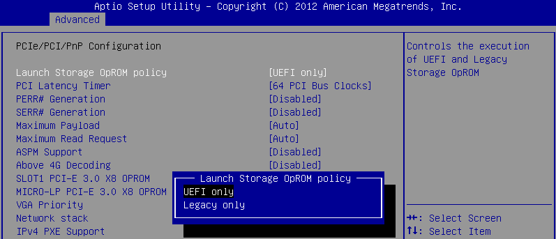
On the Boot tab, specify the UEFI network connection as the first boot device. For example:
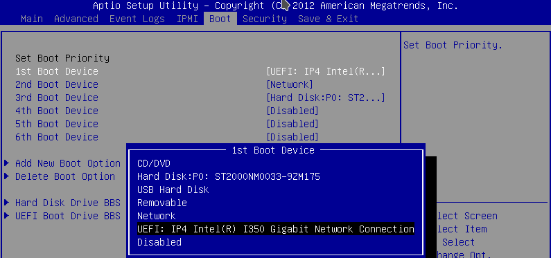
During comissioning through MAAS, verify that the server uses UEFI. For example:
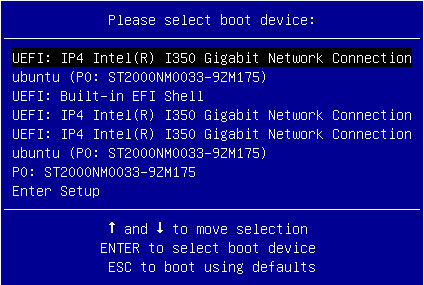
Note
If you perform standard PXE boot, the MAAS commissioning process will not recognize UEFI.
See also
Manage kernel version
Note
This feature is available starting from the MCP 2019.2.7 maintenance update. Before using the feature, follow the steps described in Apply maintenance updates.
During a node provisioning, the default image kernel version is set by MAAS. If the node is not provisioned by MAAS, the kernel version is taken from the node image. However, you can manually configure the kernel version as required to control which kernel version to install.
To manage the kernel version:
Open your Git project repository with the Reclass model on the cluster level.
In configuration files for the required nodes, specify the following example pillar. For example, use
infra/config/init.ymlfor thecfgnode andopenstack/proxy.ymlfor theprxnodes.linux: system: kernel: type: generic extra: true headers: true version: 4.15.0-65 hwe: type: hwe version: 16.04 kernel_version: 4.15.0.65
Select from the following options:
If you perform the changes before running an MCP cluster deployment or before adding new nodes, proceed with the cluster deployment since the changes apply automatically.
If you perform the changes after the MCP cluster deployment, apply the following states from the Salt Master node:
salt '*' saltutil.sync_all salt '*' state.sls linux.system.kernel
Add a custom disk layout per node in the MCP model
In MAAS, you can define the disk layout, either flat or Logical Volume Manager
(LVM), as well as the partitioning schema per server.
This section describes how to define these parameters in the MAAS section
of the MCP model.
The disk configuration applies during the deployment process.
If you want to define the disk configuration after deployment,
you can use salt-formula-linux that also has a capability to set up LVM
partitioning. But the whole definition for each Volume Group must be either
in the maas or linux section, since the linux state cannot
override or extend an existing Volume Group created using MAAS but can create
a new one.
Caution
You can define the disk configuration in the model before the
deployment starts. But be aware that enforcing of this
configuration to MAAS using the salt state must be done
after servers are commissioned and before they are deployed.
Basically, maas.machines.storage works only if a server
is in the READY state.
Caution
The maas.machines.storage state overlaps with
the linux.storage state. Therefore, we recommend using
only one of them. If your deployment requires both, be aware that:
The
linux.storageconfiguration must match themaas.machines.storageconfiguration.MAAS may use an inexplicit mapping. For example, the following MAAS configuration will create an inexplicit mapping to
sda1. And this specificsda1device must be defined in thelinux.storageconfiguration.maas: ... vg0: type: lvm devices: - sda ...
You can use several options to design the disk layout in a deployment depending on specific use cases. This section includes three most common examples that can be combined to get your desired configuration.
To define a different disk layout with custom parameters
The default layouts used by MAAS are flat and Logical Volume Manager (LVM). Flat layout creates a root partition on the first disk of a server. LVM creates a Volume Group on this partition with one volume per root. By default, in both types of disk layout, the entire space on the first disk is used. If you want to change this behavior, redefine the disk layout parameters.
The following examples illustrate a modified configuration of the default values for partition size as well as LVM names for Volume Group and Logical Volume:
Flat layout:
maas: region: machines: server1: disk_layout: type: flat root_size: 10G #sda disk has more then 10G root_device: sda bootable_device: sda
LVM layout:
maas: region: machines: server1: disk_layout: type: lvm root_size: 20G #sda disk has more then 20G root_device: sda bootable_device: sda volume_group: vg0 volume_name: root volume_size: 10G #If not defined, whole root partition is used.
Caution
When defining the disk layout in the model, do not modify
the rest of the disk using the MAAS dashboard.
Each run of maas.machines.storage deletes and recreates
the disk configuration of a server.
Currently, this state is not idempotent.
To define a custom partitioning schema
To define a more complex configuration for disks, use the disk section
under the disk_layout parameter.
The following example illustrates how to create partitions on the sda disk
and a Volume Group with Logical Volumes on the sdb disk.
Be aware that sdb is also defined without any partitioning schema.
Therefore, you can enforce no partition to be present on sdb.
Also, due to the volume_group1 dependency on this device,
it must be defined with some configuration in the model.
In the example below, it has no partitioning schema.
Example of creating partitions and Logical Volumes:
maas:
region:
machines:
server3:
disk_layout:
type: custom
bootable_device: sda
disk:
sda:
type: physical
partition_schema:
part1:
size: 10G
type: ext4
mount: '/'
part2:
size: 2G
part3:
size: 3G
sdb:
type: physical
volume_group1:
type: lvm
devices:
- sdb
volume:
tmp:
size: 5G
type: ext4
mount: '/tmp'
log:
size: 7G
type: ext4
mount: '/var/log'
Caution
The naming convention for partition in MAAS does not allow
using custom names. Therefore, key names in YAML for partition
are always part1, part2, …, partN.
To define the software RAID
Using the disk section from the previous example, you can create
the software RAID on servers. You can use this device for LVM or
you can define a partitioning schema directly on this device.
The following example illustrates how to create raid 1 on sda and
sdb with the partitioning schema. In this example, we use flat layout
that creates a root partition on sda, but this partition is eventually
deleted because sda is defined without any partitioning schema.
Example of creating the software RAID disks:
maas:
region:
machines:
server3:
disk_layout:
type: custom
bootable_device: sda
disk:
sda:
type: physical
sdb:
type: physical
md0:
type: raid
level: 1
devices:
- sda
- sdb
partition_schema:
part1:
size: 10G
type: ext4
mount: '/'
part2:
size: 5G
part3:
size: 25G
To apply changes to MAAS
To enforce the disk configuration on servers in MAAS, run the maas state
on a node where the MAAS model is included. Usually, this is the cfg01
node.
salt-call state.sls maas.machines.storage
Now, proceed with the MCP deployment depending on your use case as described in Provision physical nodes using MAAS.
Enable NTP authentication
This section describes how to enable Network Time Protocol (NTP) authentication in a deployment model and apply it to your environment.
To configure authentication for NTP:
Log in to the Salt Master node.
Create the
classes/cluster/<cluster_name>/infra/ntp_auth.ymlfile with the following configuration as an example:ntp: client: enabled: true auth: enabled: true secrets: 1: secret_type: 'M' secret: '<Runrabbitrundigthath>' trustedkey: true 2: secret_type: 'M' secret: '<Howiwishyouwereherew>' trustedkey: true stratum: primary: server: <ntp1.example.com> key_id: 1 secondary: server: <ntp2.example.com> key_id: 2
In the
secretsandstratumsections, specify your own keys and strata servers accordingly.The
key_idparameter for each strata server represents theidof a secret from thesecretssection.The above configuration example enables authentication for two servers. For a specific use case, see README.rst at NTP Salt formula.
In the
classes/cluster/<cluster_name>/infra/init.ymlfile, include the following class to distribute the settings across all nodes:classes: - cluster.<cluster_name>.infra.ntp_auth
Apply the ntp state on the Salt Master node:
salt '*' state.sls ntp
Enable a watchdog
This section describes how to enable a watchdog in your MCP cluster and applies to both existing and new MCP deployments.
Note
This feature is available as technical preview. Use such configuration for testing and evaluation purposes only.
The watchdog detects and recovers servers from serious malfunctions which can include hardware faults as well as program errors. While operating normally, the server resets the watchdog preventing it from generating a timeout signal. Otherwise, the watchdog initiates corrective actions to restore the normal operation of a system.
This functionality can be implemented through either a watchdog timer, which is a hardware device, or a software-only softdog driver.
To install and configure the watchdog:
Log in to the Salt Master node.
In the
classes/cluster/<cluster_name>/init.ymlorclasses/cluster/<cluster_name>/init/init.ymlfile of your Reclass model, include the following class:classes: - system.watchdog.server
In the
classes/cluster/<cluster_name>/infra/config.ymlfile of your Reclass model, add the watchdog server configuration. For example:watchdog: server: admin: root enabled: true interval: 1 log_dir: /var/log/watchdog realtime: yes timeout: 60 device: /dev/watchdog # Salt Stack will automatically detect the necessary kernel module # which needs to be loaded (ex. hpwdt, iTCO_wdt). # If the hardware model is not predefined in map.jinja, the default # watchdog driver is used: softdog # You may specify the kernel module parameters if needed: kernel: parameter: soft_panic: 1 parameter: value parameter_only_without_value: none
Select from the following options:
If you are performing the initial deployment of your environment, the watchdog service will be installed during the Finalize stage of the Deploy - OpenStack pipeline. See Deploy an OpenStack environment for details.
If you are enabling the watchdog service in an existing environment, apply the changes to the deployment model to install the service:
salt \* state.sls watchdog
Verify that the watchdog service is enabled in your deployment:
salt \* cmd.run "service watchdog status"
Enable the Linux Audit system
The Linux Audit system enables the system administrator to track security-relevant events by creating an audit trail, which is a log for every action on the server. More specifically, based on the pre-configured rules, the audit system creates log entries that record system calls. By monitoring the events happening on your system, you can reveal violations of system security policies and adjust the set of audit rules to prevent further misuse or unauthorized activities within the system.
This section describes how to enable the audit system in your MCP deployment in compliance with CIS audit benchmarks and applies to both existing and new MCP deployments. Once you enable the audit system, the Fluentd service of StackLight LMA collects the audit logs and sends them to Elasticsearch for storage.
To enable the Linux Audit system:
Log in to the Salt Master node.
In the
classes/cluster/<cluster_name>/infra/init.ymlfile of your Reclass model, include the following class:classes: ... - system.auditd.server.ciscat
If required, configure the CIS-CAT rules depending on the needs of your deployment.
Select from the following options:
If you are performing the initial deployment of your environment, the
auditdservice will be installed during the MCP cluster deployment.If you are enabling the
auditdservice in an existing environment:Refresh pillars and synchronize Salt modules:
salt '*' saltutil.refresh_pillar salt '*' saltutil.sync_modules
Apply the salt state:
salt '*' state.sls salt
Apply the changes to the Reclass model by running the auditd state:
salt \* state.sls auditd
Verify that the
auditdservice is enabled in your deployment:salt \* service.status auditd
Verify that the rules are being applied as expected using the auditctl tool:
salt \* cmd.run "auditctl -l"
Configure a company name for the SSH and interactive logon disclaimer
On an SSH and interactive logon to the MCP VCP nodes, a security disclaimer displays. The disclaimer states that an unauthorized access to or misuse of a computer system is prohibited under the Computer Misuse Act 1990.
Note
The act is designed to protect computer users against wilful attacks and theft of information. The act makes it an offence to access or even attempt to access a computer system without the appropriate authorization. Therefore, if a hacker makes even unsuccessful attempts to get into a system, they can be prosecuted using this law.
This section provides an instruction on how to configure the company name managing the computer from which the operator is required to have authorization before proceeding.
To configure the company name in the logon disclaimer:
Log in to the Salt Master node.
Configure the company name for the SSH logon by specifying the company name in the
classes/cluster/<cluster_name>/openssh/server/single.ymlfile in your Reclass model:classes: - service.openssh.server - service.openssh.server.cis parameters: _param: ssh_banner_company_name: COMPANY_NAME
Configure the company name for the interactive logon by specifying the company name in the
classes/cluster/<cluster_name>/linux/system/banner.ymlfile in your Reclass model:parameters: _param: banner_company_name: COMPANY_NAME_HERE
Apply the changes:
salt -C 'I@salt:control' state.sls openssh.server.service linux.system
Now, the logon disclaimer should display the configured company name.
Configure secure SSH ciphers
For security and compliance purposes, the following SSH ciphers are disabled in MCP:
arcfourarcfour128arcfour256
The default ciphers can be changed in the
classes/cluster/<cluster_name>/openssh/server/single.yml file of your
Reclass model to satisfy the cluster needs. Mirantis highly recommends
adjusting the cipher suites according to compliance requirements as well as
applying and testing the changes on staging environments first.
The structure with enabled ciphers from openssh/server/single.yml
is converted to a comma-separated string in /etc/ssh/sshd_config.
For a list of all supported ciphers, inspect man sshd_config.5 on any node
of your MCP cluster.
Warning
The following instruction can potentially lead to security or compliance issues on your cluster. Therefore, proceed at your own risk.
To configure SSH ciphers:
Log in to the Salt Master node.
In the
classes/cluster/<cluster_name>/openssh/server/single.ymlfile of your Reclass model, add the supported SSH ciphers under theciphersparameter as follows:parameters: openssh: server: ciphers: "<cipher_name>": enabled: True
The following SSH ciphers are enabled by default in MCP:
parameters: openssh: server: ciphers: "3des-cbc": enabled: True "aes128-cbc": enabled: True "aes192-cbc": enabled: True "aes256-cbc": enabled: True "aes128-ctr": enabled: True "aes192-ctr": enabled: True "aes256-ctr": enabled: True "aes128-gcm@openssh.com": enabled: True "aes256-gcm@openssh.com": enabled: True "chacha20-poly1305@openssh.com": enabled: True "rijndael-cbc@lysator.liu.se": enabled: True
Apply the changes:
salt -C 'I@salt:control' state.sls openssh.server.service linux.system
Set custom Transmit Queue Length
The Transmit Queue Length (txqueuelen) is a TCP/IP stack network interface
value that sets the number of packets allowed per kernel transmit queue of a
network interface device.
By default, the txqueuelen value for TAP interfaces
is set to 1000 in the MCP Build ID 2019.2.0
and to 10000 in the MCP 2019.2.3 maintenance update.
You can also tune the txqueuelen value for TAP interfaces
to optimize VM network performance under high load in certain scenarios.
To set a custom Transmit Queue Length value for TAP interfaces:
Log in to the Salt Master node.
Set the
tap_custom_txqueuelenparameter for the OpenContrail or OVS compute nodes in one of the following files as required:- For the OpenContrail compute nodes, modify the
cluster/<cluster_name>/opencontrail/networking/compute.ymlfile. - For the OVS compute nodes, modify the
cluster/<cluster_name>/openstack/networking/compute.ymlfile.
Example:
linux: network: ... tap_custom_txqueuelen: 20000
- For the OpenContrail compute nodes, modify the
Apply the change:
salt '*' state.sls linux
Verify that the
txqueuelenvalue has changed:- Log in to the target node.
- Verify the output of the ifconfig <interface_name>. The
txqueuelenvalue should equal the newly set value.
Configure a CPU model
The Compute service enables you to control the guest host CPU model that is exposed to KVM virtual machines. The use cases include:
- Maximization of performance of virtual machines by exposing new host CPU features to the guest
- Ensuring a consistent default CPU value across all machines by removing the reliance on the QEMU variable default values
You can define the CPU model for your deployment by setting the cpu_mode
parameter on the Reclass cluster level. A universal default value for this
parameter does not exist as the configuration depends a lot on a particular use
case, workload needs, and compute hardware. Therefore, picking up the value for
the cpu_mode parameter is worth careful consideration.
The supported values include:
host-model- Clone the host CPU feature flags
host-passthrough- Use the host CPU model
custom- Use the CPU model defined with
[libvirt]cpu_model none- Do not set a specific CPU model. For example, with the
[libvirt] virt_typeas KVM/QEMU, the default CPU model from QEMU will be used providing a basic set of CPU features that are compatible with most hosts
The cpu_mode parameter directly affects the possibility of performing the
VM migration. To be able to migrate a VM from one compute host to another one,
the destination host must support the CPU flags of the guest host. If a cloud
environment is running on a heterogeneous hardware, the cpu_mode parameter
should be set to custom. Though, such configuration will decrease the
workload performance.
Starting from the MCP maintenance update 2019.2.10, you can use the custom
CpuFlagsFilter Nova scheduler filter. The filter works only for live
migrations and ensures that the CPU features of a live migration source host
match the target host. Use the CpuFlagsFilter filter only if your
deployment meets the following criteria:
- The CPU mode is set to
host-passthroughorhost-model. - The OpenStack compute nodes have heterogeneous CPUs.
- The OpenStack compute nodes are not organized in aggregates with the same CPU in each aggregate.
Configure Galera parameters
This section provides an instruction on how to configure the parameters of the
MySQL my.cnf configuration file by overriding them on the cluster level of
the Reclass model.
Note
The capability to configure the tmp_table_size,
max_heap_table_size, and table_open_cache parameters is available
starting from the 2019.2.5 maintenance update. To enable the feature, follow
the steps described in Apply maintenance updates.
To configure parameters of the MySQL configuration file:
Open your project Git repository with the Reclass model on the cluster level.
In
cluster/<cluster_name>/openstack/database/init.yml, define the following parameters as required. The available values for<role>aremasterorslave.Warning
The following list may be not exhaustive.
Galera configurable parameters¶ Section Galera parameter Pillar parameter key name [mysql] ssl-ca galera:<role>:ssl:ca_file [0] ssl-cert galera:<role>:ssl:cert_file [0] ssl-key galera:<role>:ssl:key_file [0] [mysqld] bind-address galera:<role>:bind:address max_connections galera:<role>:max_connections log_error galera:<role>:error_log_path [1] table_open_cache galera:<role>:table_open_cache tmp_table_size galera:<role>:tmp_table_size max_heap_table_size galera:<role>:max_heap_table_size innodb_buffer_pool_size galera:<role>:innodb_buffer_pool_size innodb_read_io_threads galera:<role>:innodb_read_io_threads innodb_write_io_threads galera:<role>:innodb_write_io_threads wsrep_provider galera:<role>:wsrep_provider wsrep_slave_threads galera:<role>:wsrep_slave_threads wsrep_sst_auth (galera:<role>:sst:user):(galera:<role>:sst:password) [2] wsrep_node_address galera:<role>:bind:address [xtrabackup] parallel galera:<role>:xtrabackup_parallel For example:
parameters: galera: slave: bind: address: 127.0.0.1
| [0] | (1, 2, 3) Requires galera:<role>:ssl:enabled == true. |
| [1] | Requires galera:<role>:error_log_enabled == true. |
| [2] | The parameter is concatenated from two pillar values. |
Configure HAProxy parameters
Note
This feature is available starting from the MCP 2019.2.5 maintenance update. Before enabling the feature, follow the steps described in Apply maintenance updates.
This section provides an instruction on how to configure the parameters of the HAProxy configuration file by overriding them on the cluster level of the Reclass model. For the list of all available global parameters, see the official HAProxy documentation.
To configure global parameters of the HAProxy configuration file:
Open your project Git repository with the Reclass model on the cluster level.
In
cluster/<cluster_name>/openstack/init.yml, define the parameters in theglobalsection using thehaproxy:proxy:globalpillar and the following pattern:parameters: haproxy: proxy: global: <key>: <value>
In the configuration above,
<key>is any required parameter and<value>is its value that can be a number, string, or boolean. Replace all dot.signs in the parameter key names with undescores_in the pillar definiton. For example, thetune.ssl.cachesizeparameter must betune_ssl_cachesizein the pillar configuration.Example configuration:
parameters: haproxy: proxy: global: tune_ssl_cachesize: 4
Some keys in the global configuration have dedicated configurable pillar keys in the pillar structure and are kept for the backward compatibility. If both parameters are defined, the one from
haproxy:proxy:globalpillar has higher priority and overwrites any other values. For example, thenbprocvalue can be defined with bothhaproxy:proxy:nbprocandhaproxy:proxy:global:nbprocparameters.The timeout values are assumed to be defined in
msif no other unit is specifically defined. For details, see HAProxy documentation.
Use secured sources for mirrors, repositories, and files
Note
This feature is available starting from the MCP 2019.2.5 maintenance update. Before enabling the feature, follow the steps described in Apply maintenance updates.
This section provides an instruction on how to configure your cluster model if you plan to download Debian packages, Git mirrors, VM images, or any files required for cluster deployment from a secured HTTP/HTTPS server that can be accessible through login credentials. Such functionality may be required for offline installations when internal mirrors are secured.
If the source HTTP/HTTPS server is secured, the source or url
parameters should still include the user ID and password, for example,
http://user:password@example.mirantis.com/xenial. Previously,
MCP did not enable you to use encrypted pillar inside another variable.
Starting from MCP 2019.2.5, you can use a secured HTTP/HTTPS server even if
the secrets encryption feature in Reclass is enabled as described in
Enable all secrets encryption.
Warning
We recommend that you apply the procedure before the cluster deployment to avoid the cluster breakdown and to automatically apply the changes.
To define secured APT repositories on the cluster nodes:
Note
The exemplary default structure of the APT repositories definition in the cluster model:
linux:
system:
repo:
repo-example:
source: 'deb http://example.com/ubuntu xenial main'
Define a secured APT repository, for example:
linux: system: repo: repo-example: secure: true url: example.com/ubuntu arch: deb protocol: http user: foo password: bar distribution: xenial component: main
Define the APT repositories in case of several APT repositories under the same HTTP/HTTPS secured server with the same credentials. The exemplary structure:
linux: system: common_repo_secured: arch: deb protocol: http user: foo password: bar distribution: xenial component: main repo: test1: secure: true url: example1.com/ubuntu test2: secure: true url: example2.com/ubuntu
Warning
We do not recommend that you apply the changes after the MCP cluster deployment. Though, on your own responsibility, you can apply the changes as follows:
Log in to the Salt Master node.
Run:
salt '*' saltutil.refresh_pillar salt '*' state.apply linux.system.repo
To define a secured file source on cluster nodes:
Note
The exemplary default structure of the file sources definition in the cluster model:
linux:
system:
file:
/tmp/sample.txt:
source: http://techslides.com/demos/samples/sample.txt
source_hash: 5452459724e85b4e12277d5f8aab8fc9
sample2.txt:
name: /tmp/sample2.txt
source: http://techslides.com/demos/samples/sample.txt
Define a secured file source, for example:
linux:
system:
file:
sample3.tar.gz:
name: /tmp/sample3.tar.gz
secured_source:
protocol: http #optional
user: username
password: password
url: wordpress.org/latest.tar.gz
secured_hash: #optional
url: wordpress.org/latest.tar.gz.md5
Warning
We do not recommend that you apply the changes after the MCP cluster deployment. Though, on your own responsibility, you can apply the changes as follows:
Log in to the Salt Master node.
Run:
salt '*' saltutil.refresh_pillar salt '*' state.apply linux.system.repo
To define a secured image source on cluster nodes:
Note
The exemplary default structure of the image sources definition in cluster model:
salt:
control:
cluster:
cluster-name:
node:
node1:
provider: node01.domain.com
size: medium
image: http://ubuntu.com/download/ubuntu.qcow2
Define a secured image sources. The exemplary structure:
salt: control: cluster: cluster-name: node: node1: provider: node01.domain.com size: medium image_source: secured: true protocol: http user: foo password: bar url_prefix: ubuntu.com/download url_path: ubuntu.qcow2
Define the image sources in case of several images from the same HTTP/HTTPS secured server with the same credentials. The exemplary structure:
salt: control: common_image_source: protocol: http user: foo password: bar url_prefix: ubuntu.com/download cluster: cluster-name: node: node1: provider: node01.domain.com size: medium image_source: secured: true url_path: ubuntu-xenial.qcow2 node2: provider: node02.domain.com size: medium image_source: secured: true url_path: ubuntu-bionic.qcow2
Warning
Do not apply the changes after the MCP cluster deployment to avoid the cluster breakdown.
To define a secured Git repositories source for CI/CD nodes:
Update the configuration of the Gerrit project source:
Note
The exemplary default structure of the Gerrit project sources in cluster model:
gerrit: client: enabled: True project: test_salt_project: enabled: true upstream: https://github.com/example/library
Define a secured Gerrit project source, fore example:
gerrit: client: enabled: True project: test_salt_project: enabled: true upstream_secured: true protocol: https username: foo password: bar address: github.com/example/library
If the target Gerrit repositories are any of
mcp-ci/pipeline-libraryormk/mk-pipelines, or they are required for the pipelines execution in Jenkins, add the Jenkins login credentials:Navigate to the root folder of your cluster model. On the Salt Master node, this is the
/srv/salt/reclassdirectory.Add the following parameters into
./classes/cluster/<cluster_name>/infra/config/jenkins.ymlfor Jenkins on the Salt Master node and./classes/cluster/<cluster_name>/cicd/control/leader.ymlfor Jenkins on the CI/CD nodes:parameters: _param: source_git_username: <ENCRYPTED_USERNAME> source_git_password: <ENCRYPTED_PASSWORD>
Include the
system.jenkins.client.credential.source_gitclass into same files for both Jenkins instances:classes: ... - system.jenkins.client.credential.source_git ...
Warning
We do not recommend that you apply the changes after the MCP cluster deployment. Though, on your own responsibility, you can apply the changes as follows:
Log in to the Salt Master node.
Refresh the pillars:
salt -C 'I@gerrit:client' saltutil.refresh_pillar salt -C 'I@jenkins:client' saltutil.refresh_pillar
Apply the gerrit and jenkins states:
salt -C 'I@gerrit:client' state.apply gerrit.client salt -C 'I@jenkins:client' state.apply jenkins.client
Advanced configuration
MCP exposes a number of advanced configuration options.
Enable NFV features
Network Functions Virtualization (NFV) is a powerful technology that leverages virtualization of particular network functions which allows a better flexibility in network administration and enables you to use network hardware more efficiently.
MCP supports the following NFV features:
- Data Plane Development Kit or DPDK is a set of libraries and drivers to perform fast packet processing in the user space that OVS/vRouter can use to move network packets processing from a kernel to a user space. OVS/vRouter with DPDK acceleration on compute nodes reduces the processing time of network packets transferred between a host’s network interface and a guest bypassing the host’s kernel. Moreover, DPDK leverages benefits of usage of other technologies such as Huge Pages, CPU pinning, and NUMA topology scheduling.
- SR-IOV is an extension to the PCI Express (PCIe) specification that enables a network adapter to separate access to its resources among various PCIe hardware functions: Physical Function (PF) and Virtual Functions (VFs). As a result, you can achieve near bare-metal performance, since network devices can forward traffic directly to a VF bypassing the host.
- Multiqueue for DPDK-based vrouters enables the scaling of packet sending/receiving processing to the number of available vCPUs of a guest by using multiple queues.
The following table shows compatibility matrix for MCP of NFV features for different deployments.
| Type | Host OS | Kernel | HugePages | DPDK | SR-IOV | NUMA | CPU pinning | Multiqueue |
|---|---|---|---|---|---|---|---|---|
| OVS | Xenial | 4.8 | Yes | No | Yes | Yes | Yes | Yes |
| Kernel vRouter | Xenial | 4.8 | Yes | No | Yes | Yes | Yes | Yes |
| DPDK vRouter | Trusty | 4.4 | Yes | Yes | No | Yes | Yes | No (version 3.2) |
| DPDK OVS | Xenial | 4.8 | Yes | Yes | No | Yes | Yes | Yes |
Enable DPDK
Enabling Data Plane Development Kit (DPDK) strongly requires Huge Pages configuration before an application start. To perform fast packet processing, a DPDK-based network application may require to use isolated CPUs and resources spread on the multi-NUMA topology. These configurations are common for both OVS and OpenContrail.
Warning
Before you proceed with the DPDK enabling, verify that you have performed the following procedures:
Limitations
The usage of the OVS DPDK or OpenContrail DPDK features in MCP includes the following limitations.
OVS DPDK limitations:
- OVS DPDK can be used only for tenant traffic
- Compute with DPDK cannot be used for non-DPDK workload
- When deployed with StackLight LMA, the
libvirt_domain_interface_stats_*metrics are not available
OpenContrail DPDK limitations:
- When deployed with StackLight LMA, the
libvirt_domain_interface_stats_*metrics are not available
Enable OVS DPDK
This section explains how to prepare for and enable OVS DPDK in MCP.
Warning
Before you proceed with the DPDK enabling, verify that you have performed the following procedures:
Prepare your environment for OVS DPDK
This section describes the initialization steps needed to prepare your deployment for the enablement of the OVS DPDK feature.
Warning
Before you proceed with the DPDK enabling, verify that you have performed the following procedures:
To prepare your environment for OVS DPDK:
Specify the DPDK driver.
DPDK Environment Abstract Layer(EAL) uses either Userspace I/O (UIO) module or VFIO to provide userspace access on low-level buffers. MCP supports both configurations.
Note
To use VFIO approach, verify that both kernel and BIOS are configured to use I/O virtualization. This requirement is similar to SR-IOV Intel IOMMU and VT-d being enabled.
To use one of Userspace I/O drivers, define the
compute_dpdk_driverparameter. For example:compute_dpdk_driver: uio # vfio
In respect to the parameter specified above, configure the DPDK physical driver. There is one-to-one dependency of what driver must be selected for physical DPDK NIC based on the configured I/O mechanism. For example:
dpdk0: ... driver: igb_uio # vfio-pci
To enable the physical DPDK device to run several RX/TX queues for better packet processing, configure the following parameter specifying the number of queues to be used. For example:
dpdk0: ... n_rxq: 2 # number of RX/TX queues
Note
The increasing number of queues results in PMD threads consuming more cycles to serve physical device. We strongly recommend that you configure the number of physical queues not greater that CPUs configured for the DPDK-based application.
Enable OVS DPDK support
Before you proceed with the procedure, verify that you have performed the preparatory steps described in Prepare your environment for OVS DPDK.
While enabling DPDK for Neutron Open vSwitch, you can configure a number of settings specific to your environment that assist in optimizing your network performance, such as manual pinning and others.
To enable OVS DPDK:
Verify your NUMA nodes on the host operating system to see what vCPUs are available. For example:
lscpu | grep NUMA NUMA node(s): 1 NUMA node0 CPU(s): 0-11
Include the class to
cluster.<name>.openstack.computeand configure thedpdk0interface. Select from the following options:Single interface NIC dedicated for DPDK:
... - system.neutron.compute.nfv.dpdk ... parameters: linux: network: interfaces: ... # other interface setup … dpdk0: name: ${_param:dpdk0_name} pci: ${_param:dpdk0_pci} driver: igb_uio enabled: true type: dpdk_ovs_port n_rxq: 2 br-prv: enabled: true type: dpdk_ovs_bridgeOVS DPDK bond with 2 dedicated NICs
... - system.neutron.compute.nfv.dpdk ... parameters: linux: network: interfaces: ... # other interface setup … dpdk0: name: ${_param:dpdk0_name} pci: ${_param:dpdk0_pci} driver: igb_uio bond: dpdkbond1 enabled: true type: dpdk_ovs_port n_rxq: 2 dpdk1: name: ${_param:dpdk1_name} pci: ${_param:dpdk1_pci} driver: igb_uio bond: dpdkbond1 enabled: true type: dpdk_ovs_port n_rxq: 2 dpdkbond1: enabled: true bridge: br-prv type: dpdk_ovs_bond mode: active-backup br-prv: enabled: true type: dpdk_ovs_bridge
Calculate the hexadecimal coremask.
As well as for OpenContrail, OVS-DPDK needs logical cores parameter to be set. Open vSwitch requires two parameters:
lcoremask to DPDK processes andPMD maskto spawn threads for poll-mode packet processing drivers. Both parameters must be calculated respectively to isolated CPUs and are representing hexadecimal numbers. For example, if we need to take single CPU number 2 for Open vSwitch and 4 CPUs with numbers 5, 6, 10 and 12 for forwarding PMD threads, we need to populate parameters below with the following numbers:The
lcoresmask example: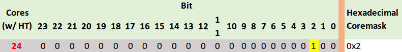
PMD CPU mask example:
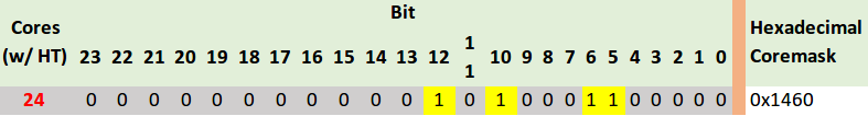
Define the parameters in the
cluster.<name>.openstack.initif they are the same for all compute nodes. Otherwise, specify them incluster.<name>.infra.config:dpdk0_nameName of port being added to OVS bridge
dpdk0_pciPCI ID of physical device being added as a DPDK physical interface
compute_dpdk_driverKernel module to provide userspace I/O support
compute_ovs_pmd_cpu_maskHexadecimal mask of CPUs to run DPDK Poll-mode drivers
compute_ovs_dpdk_socket_memSet of amount HugePages in Megabytes to be used by OVS-DPDK daemon taken for each NUMA node. Set size is equal to NUMA nodes count, elements are divided by comma
compute_ovs_dpdk_lcore_maskHexadecimal mask of DPDK lcore parameter used to run DPDK processes
compute_ovs_memory_channelsNumber of memory channels to be used.
Example
compute_dpdk_driver: uio compute_ovs_pmd_cpu_mask: "0x6" compute_ovs_dpdk_socket_mem: "1024" compute_ovs_dpdk_lcore_mask: "0x400" compute_ovs_memory_channels: "2"
Optionally, map the port RX queues to specific CPU cores.
Configuring port queue pinning manually may help to achieve maximum network performance through matching the ports that run specific workloads with specific CPU cores. Each port can process a certain number of Transmit and Receive (RX/TX) operations, therefore it is up to the Network Administrator to decide on the most efficient port mapping. Keeping a constant polling rate on some performance critical ports is essential in achieving best possible performance.
Example
dpdk0: ... pmd_rxq_affinity: "0:1,1:2"
The example above illustrates pinning of the queue 0 to core 1 and pinning of the queue 1 to core 2, where cores are taken in accordance with
pmd_cpu_mask.Specify the MAC address and in some cases PCI for every node.
Example
openstack_compute_node02: name: ${_param:openstack_compute_node02_hostname} domain: ${_param:cluster_domain} classes: - cluster.${_param:cluster_name}.openstack.compute params: salt_master_host: ${_param:reclass_config_master} linux_system_codename: xenial dpdk0_name: enp5s0f1 dpdk1_name: enp5s0f2 dpdk0_pci: '"0000:05:00.1"' dpdk1_pci: '"0000:05:00.2"'If the VXLAN neutron tenant type is selected, set the local IP address on
br-prvfor VXLAN tunnel termination:... - system.neutron.compute.nfv.dpdk ... parameters: linux: network: interfaces: ... # other interface setup … br-prv: enabled: true type: dpdk_ovs_bridge address: ${_param:tenant_address} netmask: 255.255.255.0Select from the following options:
If you are performing the initial deployment of your environment, proceed with further environment configurations.
If you are making changes to an existing environment, re-run salt configuration on the Salt Master node:
salt "cmp*" state.sls linux.network,neutron
Note
For the changes to take effect, servers require a reboot.
If you need to set different values for each compute node, define them in
cluster.<NAME>.infra.config.Example
openstack_compute_node02: name: ${_param:openstack_compute_node02_hostname} domain: ${_param:cluster_domain} classes: - cluster.${_param:cluster_name}.openstack.compute params: salt_master_host: ${_param:reclass_config_master} linux_system_codename: xenial dpdk0_name: enp5s0f1 dpdk1_name: enp5s0f2 dpdk0_pci: '"0000:05:00.1"' dpdk1_pci: '"0000:05:00.2"' compute_dpdk_driver: uio compute_ovs_pmd_cpu_mask: "0x6" compute_ovs_dpdk_socket_mem: "1024" compute_ovs_dpdk_lcore_mask: "0x400" compute_ovs_memory_channels: "2"
Enable OpenContrail DPDK
OpenContrail 4.x uses DPDK libraries version 17.02.
Caution
Starting from OpenContrail version 4.x, the Mellanox NICs are not supported in the DPDK-based OpenContrail deployments.
A workload running on a DPDK vRouter does not provide better pps if an application is not DPDK-aware. The performance result is the same as for kernel vRouter.
To enable the OpenContrail DPDK pinning:
Verify that you have performed the following procedures:
Verify your NUMA nodes on the host operating system to identify the available vCPUs. For example:
lscpu | grep NUMA NUMA node(s): 1 NUMA node0 CPU(s): 0-11
Include the following class to
cluster.<name>.openstack.computeand configure thevhost0interface:classes: ... - system.opencontrail.compute.dpdk ... parameters: linux: network: interfaces: ... # other interface setup ... vhost0: enabled: true type: eth address: ${_param:single_address} netmask: 255.255.255.0 name_servers: - 8.8.8.8 - 1.1.1.1
Set the parameters in
cluster.<name>.openstack.initon all compute nodes:compute_vrouter_tasksetHexadecimal mask of CPUs used for DPDK-vRouter processes
compute_vrouter_socket_memSet of amount HugePages in Megabytes to be used by vRouter-DPDK taken for each NUMA node. Set size is equal to NUMA nodes count, elements are divided by comma
compute_vrouter_dpdk_pciPCI of a DPDK NIC. In case of BOND there must be 0000:00:00.0
Calculate the hexadecimal mask. To enhance vRouter with DPDK technology, several isolated host CPUs should be used for such DPDK processes as statistics, queue management, memory management, and poll-mode drivers. To perform this, you need to configure the hexadecimal mask of CPUs to be consumed by vRouter-DPDK.
The way to calculate the hexadecimal mask is simple as a set of CPUs corresponds to the bits sequence size of CPUs number.
0on i-th place in this sequence means that CPU numberiwill not be taken for usage, and1has the opposite meaning. Simple translation of binary-to-hexadecimal based on bit sequence of size 24 is illustrated below (vRouter is bound to 4 cores: 14,13,2,1.)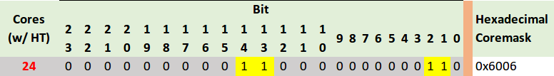
Pass the hexadecimal mask to vRouter-DPDK command line using the following parameters. For example:
compute_vrouter_taskset: "-c 1,2" # or hexadecimal 0x6 compute_vrouter_socket_mem: '1024' # or '1024,1024' for 2 NUMA nodes
Specify the MAC address and in some cases PCI for every node.
Example
openstack_compute_node02: name: ${_param:openstack_compute_node02_hostname} domain: ${_param:cluster_domain} classes: - cluster.${_param:cluster_name}.openstack.compute params: salt_master_host: ${_param:reclass_config_master} linux_system_codename: trusty compute_vrouter_dpdk_mac_address: 00:1b:21:87:21:99 compute_vrouter_dpdk_pci: "'0000:05:00.1'" primary_first_nic: enp5s0f1 # NIC for vRouter bindSelect from the following options:
If you are performing the initial deployment of your environment, proceed with the further environment configurations.
If you are making changes to an existing environment, re-run salt configuration on the Salt Master node:
salt "cmp*" state.sls opencontrail
Note
For the changes to take effect, servers require a reboot.
If you need to set different values for each compute node, define them in
cluster.<NAME>.infra.config.Example
openstack_compute_node02: name: ${_param:openstack_compute_node02_hostname} domain: ${_param:cluster_domain} classes: - cluster.${_param:cluster_name}.openstack.compute params: salt_master_host: ${_param:reclass_config_master} linux_system_codename: trusty compute_vrouter_dpdk_mac_address: 00:1b:21:87:21:99 compute_vrouter_dpdk_pci: "'0000:05:00.1'" compute_vrouter_taskset: "-c 1,2" compute_vrouter_socket_mem: "1024" primary_first_nic: enp5s0f1 # NIC for vRouter bind
Enable SR-IOV
Single Root I/O Virtualization (SR-IOV) is an I/O virtualization technology that allows a single PCIe device to appear as multiple PCIe devices. This helps to optimize the device performance and capacity, as well as hardware costs.
Prerequisites
If you want to use the SR-IOV feature with OpenContrail or Neutron OVS, your environment must meet the following prerequisites:
- Intel Virtualization Technology for Directed I/O (VT-d) and Active State Power Management (ASPM) must be supported and enabled in BIOS
- Physical NIC with Virtual Function (VF) driver installed Enable ASPM (Active State Power Management) of PCI Devices in BIOS. If required, upgrade BIOS to see ASPM option.
Enable generic SR-IOV configuration
The following procedure is common for both OpenVSwitch and OpenContrail. SR-IOV can be enabled before or after installation on the MCP cluster model level.
To enable SR-IOV:
Include the class to
cluster.<NAME>.openstack.compute:- system.neutron.compute.nfv.sriovNote
By default, the metadata model contains configuration for 1 NIC dedicated for SR-IOV.
Set the following parameters:
sriov_nic01_device_nameName of the interface, where the Virtual Functions are enabled
sriov_nic01_numvfsNumber of Virtual Functions
sriov_nic01_physical_networkDefault is
physnet1, label for the physical network the interface belongs to
sriov_unsafe_interruptsDefault is
False, needs to be set toTrueif your hardware platform does not support interrupt remapping
For most deployments with 1 NIC for SR-IOV, we recommend the following configuration in
cluster.<name>.openstack.initon all compute nodes:sriov_nic01_device_name: eth1 sriov_nic01_numvfs: 7 sriov_nic01_physical_network: physnet3
If you need to set different values for each compute node, specify them in
cluster.<name>.infra.config.Example
openstack_compute_node02: name: ${_param:openstack_compute_node02_hostname} domain: ${_param:cluster_domain} classes: - cluster.${_param:cluster_name}.openstack.compute params: salt_master_host: ${_param:reclass_config_master} linux_system_codename: xenial sriov_nic01_device_name: eth1 sriov_nic01_numvfs: 7 sriov_nic01_physical_network: physnet3If your hardware does not support interrupt remapping, set the following parameter:
sriov_unsafe_interrupts: True
If you need more than one NIC on a compute node, set the following parameters in
cluster.<NAME>.openstack.compute.Example
... nova: compute: sriov: sriov_nic01: devname: eth1 physical_network: physnet3 sriov_nic02: devname: eth2 physical_network: physnet4 sriov_nic03: devname: eth3 physical_network: physnet5 sriov_nic04: devname: eth4 physical_network: physnet6 linux: system: kernel: sriov: True unsafe_interrupts: False sysfs: sriov_numvfs: class/net/eth1/device/sriov_numvfs: 7 class/net/eth2/device/sriov_numvfs: 15 class/net/eth3/device/sriov_numvfs: 15 class/net/eth4/device/sriov_numvfs: 7Enable the kernel boot parameter for the OpenStack compute node:
linux: system: kernel: boot_options: - intel_iommu=on
Select from the following options:
If you are performing the initial deployment of your environment, proceed with the further environment configurations.
If you are making changes to an existing environment:
Run the virt-host-validate command from an OpenStack compute node to ensure that it is ready for SR-IOV.
Re-run the salt configuration on the Salt Master node:
salt "cmp*" state.sls linux,nova
Reboot the OpenStack compute nodes one by one as described in MCP Operations Guide: Reboot a compute node.
Configure SR-IOV with OpenContrail
Since OpenContrail does not use Neutron SR-IOV agents, it does not require any special changes on the Neutron side. Port configuration can be done through the Neutron APIs or the OpenContrail UI.
Configure SR-IOV with OpenVSwitch
Neutron OVS requires enabling of the sriovnicswitch mechanism driver on
the Neutron server side and the neutron-sriov-nic-agent running on each
compute node with this feature enabled.
To configure SR-IOV with OpenVSwitch:
Include the class to
cluster.<NAME>.openstack.compute:- system.neutron.compute.nfv.sriovNote
By default, the metadata model contains configuration for 1 NIC dedicated for SR-IOV.
Include the class to
cluster.<NAME>.openstack.control:- system.neutron.control.openvswitch.sriovIf you need more than 1 NIC, extend the previous configuration by extra Neutron
cluster.<NAME>.openstack.compute.Example
... neutron: compute: backend: sriov: sriov_nic01: devname: eth1 physical_network: physnet3 sriov_nic02: devname: eth2 physical_network: physnet4 sriov_nic03: devname: eth3 physical_network: physnet5 sriov_nic04: devname: eth4 physical_network: physnet6
Create instances with SR-IOV ports
To enable the SR-IOV support, you must create virtual instances with SR-IOV ports.
To create virtual instances with SR-IOV ports:
Create a network and a subnet with a segmentation ID. For example:
neutron net-create --provider:physical_network=physnet3 \ --provider:segmentation_id=100 net04 neutron subnet-create net04 a.b.c.d/netmask
Request the ID of the Neutron network where you want the SR-IOV port to be created. For example:
net_id=`neutron net-show net04 | grep "\ id\ " | awk '{ print $4 }'`
Create an SR-IOV port with one of the available VNIC driver types that are
direct,normal,direct-physical, andmacvtap:port_id=`neutron port-create $net_id --name sriov_port \ --binding:vnic_type direct | grep "\ id\ " | awk '{ print $4 }'`
Create a virtual instance with the SR-IOV port created in step 3:
nova boot --flavor m1.large --image ubuntu_14.04 --nic port-id=$port_id test-sriov
See also
Using SR-IOV functionality in the official OpenStack documentation
See also
Enable Huge Pages
Huge Pages is a technology that supports 2MB and 1GB size memory pages. Huge Pages reduces time to access data stored in the memory by using bigger memory pages, which leads to fewer page entries to look up by CPU when choosing a page associated with a current process. Use of Huge Pages is beneficial in operations and processes that require large amount of memory.
Warning
Verify that CPU supports HugePages before you proceed.
Enable the Huge Pages support
This section exaplains how to configure the support for the Huge Pages feature in your MCP depoyment.
To enable Huge Pages:
Log in to the host machine.
To verify that CPU supports Huge Pages, analyze the system response of the following command:
cat /proc/cpuinfoIn the system output, search for the parameters:
- PSE - support of 2MB hugepages
- PDPE1GB - support of 1GB hugepages
Include the class in
cluster.<name>.openstack.compute:- system.nova.compute.nfv.hugepages
Set the parameters in
cluster.<name>.openstack.initon all compute nodes:compute_hugepages_size: 1G # or 2M compute_hugepages_count: 40 compute_hugepages_mount: /mnt/hugepages_1G # or /mnt/hugepages_2M
Select from the following options:
If you are performing the initial deployment your environment, proceed with the further environment configurations.
If you are making changes to an existing environment, re-run the salt configuration on the Salt Master node:
salt "cmp*" state.sls linux,nova
Reboot the affected servers.
If you need to set different values for each compute node, define them in
cluster.<name>.infra.configfor each node.Example:
openstack_compute_node02: name: ${_param:openstack_compute_node02_hostname} domain: ${_param:cluster_domain} classes: - cluster.${_param:cluster_name}.openstack.compute params: salt_master_host: ${_param:reclass_config_master} linux_system_codename: xenial compute_hugepages_size: 1G # or 2M compute_hugepages_count: 40 compute_hugepages_mount: /mnt/hugepages_1G # or /mnt/hugepages_2M
Boot a virtual machine with Huge Pages
This section explains how to boot a VM with Huge Pages.
To boot a virtual machine with Huge Pages:
Create a new flavor or use an existing one to use with Huge Pages. To create a new image flavor:
. openrc admin admin nova flavor-create huge 999 1024 4 1
Add the size of huge pages to the image flavor:
nova flavor-key huge set hw:mem_page_size=2048
Verify the image flavor exists:
nova flavor-show huge
Example of system response
+----------------------------+------------------------------+ | Property | Value | +----------------------------+------------------------------+ | OS-FLV-DISABLED:disabled | False | | OS-FLV-EXT-DATA:ephemeral | 0 | | disk | 4 | | extra_specs | {"hw:mem_page_size": "2048"} | | id | 7 | | name | huge | | os-flavor-access:is_public | True | | ram | 1024 | | rxtx_factor | 1.0 | | swap | | | vcpus | 1 | +----------------------------+------------------------------+
Create a new image or use an existing image. You need an Ubuntu image and the default Cirros image.
To create a new Ubuntu image:
glance --os-image-api-version 1 image-create --name ubuntu \ --location https://cloud-images.ubuntu.com/trusty/current/trusty-server-cloudimg-amd64-disk1.img \ --disk-format qcow2 --container-format bare
Boot a new instance using the created flavor:
nova boot --flavor huge --image ubuntu inst1
Verify that the new VM uses 512 huge pages:
grep Huge /proc/meminfo
Example of system response
AnonHugePages: 1138688 kB HugePages_Total: 1024 HugePages_Free: 512 HugePages_Rsvd: 0 HugePages_Surp: 0 Hugepagesize: 2048 kB
Configure NUMA and CPU pinning architecture
NUMA and CPU pinning is a shared memory architecture that describes the placement of main memory modules on processors in a multiprocessor system. You can leverage NUMA when you have data strongly associated with certain tasks or users. In such case, CPU can use its local memory module to access data reducing access time.
NUMA usage is beneficial on particular workloads, for example, on configurations where data is often associated with certain tasks or users.
Enable NUMA and CPU pinning
Before you proceed with enabling DPDK in your deployment, the NUMA and CPU pinning enablement is required.
To enable NUMA and CPU pinning:
Verify your NUMA nodes on the host operating system:
lscpu | grep NUMA
Example of system response
NUMA node(s): 1 NUMA node0 CPU(s): 0-11
Include the class to
cluster.<NAME>.openstack.compute:- system.nova.compute.nfv.cpu_pinning
Set the parameters in
cluster.<name>.openstack.initon all compute nodes:compute_kernel_isolcpuSet of host CPUs to be isolated from system. Kernel will not assign internal processes on this set of CPUs. This parameter is configured in
grub
nova_cpu_pinningSubset of CPUs isolated on previous step. This parameter is used by Nova to run VMs only on isolated CPUs with dedicated pinning. Nova vCPU pinning set is configured in the
nova.conffile after system isolates appropriate CPUs
Example
nova_cpu_pinning: "1,2,3,4,5,7,8,9,10,11" compute_kernel_isolcpu: ${_param:nova_cpu_pinning}
Select from the following options:
If you are performing the initial deployment, proceed with the further environment configurations.
If you are making changes to an existing environment, re-run the salt configuration on the Salt Master node:
salt "cmp*" state.sls linux,nova
Note
To take effect, servers require a reboot.
If you need to set different values for each compute node, define them in
cluster.<name>.infra.config.Example
openstack_compute_node02: name: ${_param:openstack_compute_node02_hostname} domain: ${_param:cluster_domain} classes: - cluster.${_param:cluster_name}.openstack.compute params: salt_master_host: ${_param:reclass_config_master} linux_system_codename: xenial nova_cpu_pinning: "1,2,3,4,5,7,8,9,10,11" compute_kernel_isolcpu: "1,2,3,4,5,7,8,9,10,11"
Boot a VM with two NUMA nodes
This example demonstrates booting a VM with two NUMA nodes.
To boot VM with two NUMA nodes:
Create a new flavor or use an existing one to use with NUMA. To create a new flavor, run:
. openrc admin admin nova flavor-create m1.numa 999 1024 5 4
Add
numa_nodesto the flavor.Note
vCPUs and RAM will be divided equally between the NUMA nodes.
nova flavor-key m1.numa set hw:numa_nodes=2 nova flavor-show m1.numa
Example of system response:
+----------------------------+------------------------+ | Property | Value | +----------------------------+------------------------+ | OS-FLV-DISABLED:disabled | False | | OS-FLV-EXT-DATA:ephemeral | 0 | | disk | 5 | | extra_specs | {"hw:numa_nodes": "2"} | | id | 999 | | name | m1.numa | | os-flavor-access:is_public | True | | ram | 1024 | | rxtx_factor | 1.0 | | swap | | | vcpus | 4 | +----------------------------+------------------------+
Create a new image or use an existing image.
Note
You need an Ubuntu image and the default Cirros image.
To create a new Ubuntu image:
glance --os-image-api-version 1 image-create --name ubuntu \ --location https://cloud-images.ubuntu.com/trusty/current/\ trusty-server-cloudimg-amd64-disk1.img \ --disk-format qcow2 --container-format bare
To enable SSH connections:
Add a new rule to the security group:
nova secgroup-add-rule default tcp 22 22 0.0.0.0/0
Create a new SSH key pair or use the existing key pair. To create a new ssh key pair:
ssh-keygen
Add the key pair to Nova:
nova keypair-add --pub_key ~/.ssh/id_rsa.pub my_kp
Verify free memory before you boot the VM:
numactl -HExample of system response:
available: 2 nodes (0-1) node 0 cpus: 0 1 node 0 size: 3856 MB node 0 free: 718 MB node 1 cpus: 2 3 node 1 size: 3937 MB node 1 free: 337 MB node distances: node 0 1 0: 10 20 1: 20 10
Boot a new instance using the created flavor:
nova boot --flavor m1.numa --image ubuntu --key-name my_kp inst1
Verify if free memory has been changed after booting the VM:
numactl -HExample of system response:
available: 2 nodes (0-1) node 0 cpus: 0 1 node 0 size: 3856 MB node 0 free: 293 MB # was 718 MB node 1 cpus: 2 3 node 1 size: 3937 MB node 1 free: 81 MB # was 337 MB node distances: node 0 1 0: 10 20 1: 20 10
Retrieve the instance’s IP:
nova show inst1 | awk '/network/ {print $5}'
Example of system response:
10.0.0.2Connect to the VM using SSH:
ssh ubuntu@10.0.0.2Install
numactl:sudo apt-get install numactl
Verify the NUMA topology on the VM:
numactl -HExample of system response:
available: 2 nodes (0-1) node 0 cpus: 0 1 node 0 size: 489 MB node 0 free: 393 MB node 1 cpus: 2 3 node 1 size: 503 MB node 1 free: 323 MB node distances: node 0 1 0: 10 20 1: 20 10
Boot a VM with CPU and memory pinning
This example demonstrates booting VM with CPU and memory pinning.
To boot VM with CPU and memory pining:
Create a new flavor with specific division of vCPUs and RAM between the NUMA nodes:
. openrc admin admin nova flavor-create m1.numa_2 9992 1024 5 4
Add
numa_nodesand other specific options to the flavor:nova flavor-key m1.numa_2 set hw:numa_nodes=2 hw:numa_cpus.0=0,2 \ hw:numa_cpus.1=1,3 hw:numa_mem.0=324 hw:numa_mem.1=700 nova flavor-show m1.numa_2 | grep extra
Example of system response:
| extra_specs | {"hw:numa_cpus.0": "0,2", "hw:numa_cpus.1": "1,3", \ "hw:numa_nodes": "2", "hw:numa_mem.1": "700", "hw:numa_mem.0": "324"} |
Create a new image or use an existing image.
Note
You need an Ubuntu image or the default Cirros image.
To create a new Ubuntu image:
glance --os-image-api-version 1 image-create --name ubuntu \ --location https://cloud-images.ubuntu.com/trusty/current/\ trusty-server-cloudimg-amd64-disk1.img \ --disk-format qcow2 --container-format bare
To enable SSH connections:
Add a new rule to the security group:
nova secgroup-add-rule default tcp 22 22 0.0.0.0/0
Create a new SSH key pair or use the existing key pair. To create a new ssh key pair, run:
ssh-keygen
Add the key pair to Nova:
nova keypair-add --pub_key ~/.ssh/id_rsa.pub my_kp
Boot a new instance using the created flavor:
nova boot --flavor m1.numa_2 --image ubuntu --key-name my_kp inst2
Verify if free memory has been changed after booting the VM:
numactl -HExample of system response:
available: 2 nodes (0-1) node 0 cpus: 0 1 node 0 size: 3856 MB node 0 free: 293 MB # was 718 MB node 1 cpus: 2 3 node 1 size: 3937 MB node 1 free: 81 MB # was 337 MB node distances: node 0 1 0: 10 20 1: 20 10
Retrieve the instance’s IP:
nova show inst2 | awk '/network/ {print $5}'
Example of system response:
10.0.0.3Connect to the VM using SSH:
ssh ubuntu@10.0.0.3Install
numactl:sudo apt-get install numactlVerify the NUMA topology on the VM:
numactl -HExample of system response:
available: 2 nodes (0-1) node 0 cpus: 0 2 node 0 size: 303 MB node 0 free: 92 MB node 1 cpus: 1 3 node 1 size: 689 MB node 1 free: 629 MB node distances: node 0 1 0: 10 20 1: 20 10
You can see that the NUMA topology has two NUMA nodes. Total RAM size is about 1GB:
node-0CPUs are0and2node-1CPUs are1and3,node-1RAM is about 324 MBnode-2RAM is about 700 as specified in them1.numa_2flavor
Enable Multiqueue
The MCP Multiqueue enables the scaling of packet sending/receiving processing to the number of available vCPUs of a guest by using multiple queues. The feature includes:
- Multiqueue for DPDK-based vrouters
Is supported by OpenVSwitch only. Underlay configuration for OVS is a part of DPDK interfaces and is defined by the
n_rxqparameter. For example:... - system.neutron.compute.nfv.dpdk ... parameters: linux: network: interfaces: ... # other interface setup … dpdk0: name: ${_param:dpdk0_name} pci: ${_param:dpdk0_pci} driver: igb_uio bond: dpdkbond1 enabled: true type: dpdk_ovs_port n_rxq: 2 dpdk1: name: ${_param:dpdk1_name} pci: ${_param:dpdk1_pci} driver: igb_uio bond: dpdkbond1 enabled: true type: dpdk_ovs_port n_rxq: 2
- Multiqueue Virtio
Is supported by OpenContrail and OVS
Provision a VM with Multiqueue
To provision a VM with Multiqueue:
Set the image metadata property with the Multiqueue enabled:
nova image-meta <IMAGE_NAME> set hw_vif_multiqueue_enabled="true"
After the VM is spawned, use the following command on the virtio interface in the guest to enable multiple queues inside the VM:
ethtool –L <INTERFACE_NAME> combined <#queues>
Configure load balancing with OpenStack Octavia
You can use the OpenStack Octavia service to provide advanced load balancing in your OpenStack environment. For the Octavia architecture details and limitations, see: MCP Reference Architecture: Plan load balancing with OpenStack Octavia.
You can enable Octavia before or after you have an operational OpenStack environment with Neutron OVS as a networking solution deployed by MCP.
Enable Octavia on a new OpenStack environment
You can enable Octavia before deploying an OpenStack-based MCP cluster and automatically deploy it together with other OpenStack components using the dedicated Jenkins pipeline.
To enable Octavia on a new OpenStack environment:
- While generating a deployment metadata model for your new OpenStack-based
MCP cluster as described in Create a deployment metadata model, select
the following parameters in the Model Designer web UI:
- OVS as a networking engine in the Infrastructure parameters section
- Openstack octavia enabled in the Product parameters section
- For MCP versions starting from the 2019.2.8 maintenance update:
- To use the amphora HA mode, set Octavia amphora topology
to
ACTIVE_STANDBY - To use a spare amphorae pool for the Octavia load balancer, set the required pool size in Octavia spare amphora pool size
- To use the amphora HA mode, set Octavia amphora topology
to
- If you need TLS support with Barbican, select Barbican enabled in the Product parameters section
- TECHNICAL PREVIEW If you want to enable Octavia Cluster Manager, select Octavia Cluster Manager in the Product parameters section
- Proceed with further cluster configuration as required. Octavia will be deployed during your OpenStack environment deployment by the dedicated Jenkins pipeline. For the deployment details, see: Deploy an OpenStack environment.
See also
Enable Octavia on an existing OpenStack environment
You can enable Octavia on an operational OpenStack environment with Neutron OVS as a networking solution deployed by MCP.
To enable Octavia on an existing OpenStack environment:
Log in to the Salt Master node.
Add the following class to
cluster/<cluster_name>/openstack/database.yml:- system.galera.server.database.octavia
Add the following classes to
cluster/<cluster_name>/openstack/control/init.yml:- system.keystone.client.service.octavia - system.glance.client.image.octavia - system.nova.client.service.octavia - system.octavia.client
Select from the following options:
To run Octavia worker services in a cluster, add the following class to
cluster/<cluster_name>/openstack/control/init.yml:- system.neutron.client.service.octavia
To run a single instance of Octavia worker services, add the following class to
cluster/<cluster_name>/openstack/control/init.yml:- system.neutron.client.service.octavia.single
If Barbican support is required, add the following classes to
cluster/<cluster_name>/openstack/control/init.yml:- system.barbican.client.v1.octavia - system.barbican.client.v1.signed_images.octavia - system.salt.minion.cert.octavia.image_sign
Caution
If signing of images is disabled for Nova, do not add the images-related classes.
Add the following classes to
cluster/<cluster_name>/openstack/control.yml:- system.neutron.control.openvswitch.octavia - system.octavia.api.cluster
Note
Starting the OpenStack Queens release, the
system.neutron.control.openvswitch.octaviaclass is not required.The
system.octavia.api.clusterclass configures an Octavia API cluster to run on the OpenStack controller nodes. Alternatively, if you want to run a single instance of Octavia API, add the following class instead:- system.octavia.api.single
In
cluster/<cluster_name>/infra/config.yml, configure the Octavia Manager services (Controller Worker, Health Manager, and Housekeeping) to run on one of the gateway nodes that isgtw01by default:Add the following classes:
- system.salt.minion.ca.octavia_amphora_ca - system.salt.minion.cert.octavia.amphora_cluster_client
If you run the OpenStack gateway services in a cluster, add the following class:
- system.reclass.storage.system.openstack_gateway_single_octavia
before
- system.reclass.storage.system.openstack_gateway_cluster
If you run the OpenStack gateway services in a single mode, add the following class:
- system.reclass.storage.system.openstack_gateway_single_octavia
before
- system.reclass.storage.system.openstack_gateway_single
TECHNICAL PREVIEW If you want to add Octavia Cluster Manager, also add the following class:
- system.reclass.storage.system.openstack_gateway_cluster_octavia
Verify the classes and parameters:
Verify that the
cluster/<cluster_name>/openstack/octavia_manager.ymlfile exists and contains import of the following classes as well as a private key that will be used to log in to amphorae. For example:classes: - system.octavia.manager.single - system.salt.minion.ca.octavia_ca - system.salt.minion.cert.octavia.amphora_client parameters: _param: cluster_local_address: ${_param:single_address} octavia_private_key: | -----BEGIN RSA PRIVATE KEY----- MIIEpAIBAAKCAQEAtjnPDJsQToHBtoqIo15mdSYpfi8z6DFMi8Gbo0KCN33OUn5u OctbdtjUfeuhvI6px1SCnvyWi09Ft8eWwq+KwLCGKbUxLvqKltuJ7K3LIrGXkt+m qZN4O9XKeVKfZH+mQWkkxRWgX2r8RKNV3GkdNtd74VjhP+R6XSKJQ1Z8b7eHM10v 6IjTY/jPczjK+eyCeEj4qbSnV8eKlqLhhquuSQRmUO2DRSjLVdpdf2BB4/BdWFsD YOmX7mb8kpEr9vQ+c1JKMXDwD6ehzyU8kE+1kVm5zOeEy4HdYIMpvUfN49P1anRV 2ISQ1ZE+r22IAMKl0tekrGH0e/1NP1DF5rINMwIDAQABAoIBAQCkP/cgpaRNHyg8 ISKIHs67SWqdEm73G3ijgB+JSKmW2w7dzJgN//6xYUAnP/zIuM7PnJ0gMQyBBTMS NBTv5spqZLKJZYivj6Tb1Ya8jupKm0jEWlMfBo2ZYVrfgFmrfGOfEebSvmuPlh9M vuzlftmWVSSUOkjODmM9D6QpzgrbpktBuA/WpX+6esMTwJpOcQ5xZWEnHXnVzuTc SncodVweE4gz6F1qorbqIJz8UAUQ5T0OZTdHzIS1IbamACHWaxQfixAO2s4+BoUK ANGGZWkfneCxx7lthvY8DiKn7M5cSRnqFyDToGqaLezdkMNlGC7v3U11FF5blSEW fL1o/HwBAoGBAOavhTr8eqezTchqZvarorFIq7HFWk/l0vguIotu6/wlh1V/KdF+ aLLHgPgJ5j+RrCMvTBoKqMeeHfVGrS2udEy8L1mK6b3meG+tMxU05OA55abmhYn7 7vF0q8XJmYIHIXmuCgF90R8Piscb0eaMlmHW9unKTKo8EOs5j+D8+AMJAoGBAMo4 8WW+D3XiD7fsymsfXalf7VpAt/H834QTbNZJweUWhg11eLutyahyyfjjHV200nNZ cnU09DWKpBbLg7d1pyT69CNLXpNnxuWCt8oiUjhWCUpNqVm2nDJbUdlRFTzYb2fS ZC4r0oQaPD5kMLSipjcwzMWe0PniySxNvKXKInFbAoGBAKxW2qD7uKKKuQSOQUft aAksMmEIAHWKTDdvOA2VG6XvX5DHBLXmy08s7rPfqW06ZjCPCDq4Velzvgvc9koX d/lP6cvqlL9za+x6p5wjPQ4rEt/CfmdcmOE4eY+1EgLrUt314LHGjjG3ScWAiirE QyDrGOIGaYoQf89L3KqIMr0JAoGARYAklw8nSSCUvmXHe+Gf0yKA9M/haG28dCwo 780RsqZ3FBEXmYk1EYvCFqQX56jJ25MWX2n/tJcdpifz8Q2ikHcfiTHSI187YI34 lKQPFgWb08m1NnwoWrY//yx63BqWz1vjymqNQ5GwutC8XJi5/6Xp+tGGiRuEgJGH EIPUKpkCgYAjBIVMkpNiLCREZ6b+qjrPV96ed3iTUt7TqP7yGlFI/OkORFS38xqC hBP6Fk8iNWuOWQD+ohM/vMMnvIhk5jwlcwn+kF0ra04gi5KBFWSh/ddWMJxUtPC1 2htvlEc6zQAR6QfqXHmwhg1hP81JcpqpicQzCMhkzLoR1DC6stXdLg== -----END RSA PRIVATE KEY-----
The private key is saved to
/etc/octavia/.ssh/octavia_ssh_keyon the Octavia manager node.Note
To generate an SSH key pair, run:
ssh-keygen -b 2048 -t rsa -N "" -f ~/.ssh/octavia_ssh_key
To use a spare amphorae pool for the Octavia load balancer, specify the
spare_amphora_pool_sizeparameter as required.octavia: manager: house_keeping: spare_amphora_pool_size: 0
Verify that the following Octavia parameters are configured in
cluster/<cluster_name>/openstack/init.yml. For example:parameters: _param: octavia_version: ${_param:openstack_version} octavia_service_host: ${_param:openstack_control_address} mysql_octavia_password: <db_password> keystone_octavia_password: <keystone_password> amp_flavor_id: <amphora-flavor-id> octavia_health_manager_node01_address: 192.168.0.10 # If clusterization enaled: # octavia_health_manager_node02_address: 192.168.0.11 # octavia_health_manager_node03_address: 192.168.0.12 octavia_loadbalancer_topology: "SINGLE" octavia_public_key: | ssh-rsa AAAAB3NzaC1yc2EAAAADAQABAAABAQC2Oc8MmxBOgcG2ioijXmZ1J il+LzPoMUyLwZujQoI3fc5Sfm45y1t22NR966G8jqnHVIKe/JaLT0W3x5bCr4 rAsIYptTEu+oqW24nsrcsisZeS36apk3g71cp5Up9kf6ZBaSTFFaBfavxEo1X caR0213vhWOE/5HpdIolDVnxvt4czXS/oiNNj+M9zOMr57IJ4SPiptKdXx4qW ouGGq65JBGZQ7YNFKMtV2l1/YEHj8F1YWwNg6ZfuZvySkSv29D5zUkoxcPAPp 6HPJTyQT7WRWbnM54TLgd1ggym9R83j0/VqdFXYhJDVkT6vbYgAwqXS16SsYf R7/U0/UMXmsg0z root@cfg01
Note
- The parameter
octavia_public_keyshould contain a public key generated in the previous step. In our example, it is taken from~/.ssh/octavia_ssh_key.pub. - To use the amphora HA mode, set
octavia_loadbalancer_topologytoACTIVE_STANDBY. By default,octavia_loadbalancer_topologyis set toSINGLEto use the default load balancer topology.
- The parameter
Optional. Override the default Octavia parameters in
cluster/<cluster_name>/openstack/octavia_manager.yml. The default parameters are as follows:parameters: octavia: manager: certificates: ca_private_key: '/etc/octavia/certs/private/cakey.pem' ca_certificate: '/etc/octavia/certs/ca_01.pem' controller_worker: amp_flavor_id: ${_param:amp_flavor_id} amp_image_tag: amphora amp_ssh_key_name: octavia_ssh_key loadbalancer_topology: 'SINGLE' haproxy_amphora: client_cert: '/etc/octavia/certs/client.pem' client_cert_key: '/etc/octavia/certs/client.key' client_cert_all: '/etc/octavia/certs/client_all.pem' server_ca: '/etc/octavia/certs/ca_01.pem' health_manager: bind_ip: ${_param:octavia_hm_bind_ip} heartbeat_key: 'insecure' house_keeping: spare_amphora_pool_size: 0
Note
Starting from MCP 2019.2.7 maintenance update,
haproxy_amphoraincludes thebuild_rate_limitparameter, set to2by default. Use the parameter to configure the build rate limit for the Octavia manager.Add the configured Octavia roles to the corresponding nodes:
salt-call state.sls reclass.storage
Refresh pillars:
salt '*' saltutil.refresh_pillar
Update the Salt Minion configuration:
salt-call state.sls salt.minion.service
Create the Octavia database:
salt -C 'I@galera:master' state.sls galera salt -C 'I@galera:slave' state.sls galera -b 1
Configure HAProxy for Octavia API:
salt -C 'I@haproxy:proxy' state.sls haproxy
Configure NGINX proxy for Octavia API:
salt -C 'I@nginx:server' state.sls nginx
Create an Octavia user and endpoints in Keystone:
salt -C 'I@keystone:client' state.sls keystone.client
Upload an amphora image to Glance:
salt -C 'I@glance:client' state.sls glance.client
Create an amphora flavor and a key pair in Nova:
salt -C 'I@nova:client' state.sls nova.client
This state expects you to provide an SSH key that is used to create a key pair.
Create the Neutron resources for Octavia:
salt -C 'I@neutron:client' state.sls neutron.client
This state creates security groups and rules for amphora instances and Health Manager, a management network with a subnet for Octavia, and a port for Health Manager.
If Barbican and signing of the images for Nova are enabled, apply the following states to create a certificate and sign the Octavia amphora image:
salt -C 'I@barbican:client' state.sls salt.minion.cert salt -C 'I@barbican:client' state.sls barbican.client
Update the Salt mine:
salt '*' mine.update
Deploy the Octavia services:
salt -C 'I@octavia:api and *01*' state.sls octavia salt -C 'I@octavia:api' state.sls octavia salt -C 'I@octavia:manager' state.sls octavia
Generate certificates for the Octavia controller-amphora communication:
salt-call state.sls salt.minion.ca salt-call state.sls salt.minion.cert
Note
You may need to apply the above states twice before they succeed.
If you added Octavia Cluster Manager in previous steps, also apply the following states:
salt-call state.sls salt.minion.ca salt-call state.sls salt.minion.cert
Set up the Octavia client:
salt -C 'I@octavia:client' state.sls octavia.client
See also
Example of a load balancing topology
After you enable Octavia on your new or existing OpenStack environment as described in Configure load balancing with OpenStack Octavia, create a topology for your use case. Each topology requires you to configure the load balancer, port listener, LBaaS pool, and, optionally, the Health Monitor with a specific set of parameters.
For the purpose of this example, a topology for balancing traffic between two HTTP servers listening on port 80 is used. The topology includes the following parameters:
- Backend servers 10.10.10.7 and 10.10.10.29 in the
private-subnetsubnet run an HTTP application that listens on the TCP port 80. - The
public-subnetsubnet is a shared external subnet created by the cloud operator which is accessible from the Internet. - You must create a load balancer accessible by an IP address from
public-subnetthat will be responsible for distributing web requests between the backend servers.
For more examples, see: OpenStack Octavia documentation
Caution
Starting the OpenStack Queens release, use only the OpenStack Octavia client. For details, see OpenStack Queens documentation.
Workflow:
Log in to a controller node.
Create a load balancer:
neutron lbaas-loadbalancer-create --name lb1 private-subnet
Create an HTTP listener:
neutron lbaas-listener-create --name listener1 --loadbalancer \ lb1 --protocol HTTP --protocol-port 80
Create a LBaaS pool that will be used as default for listener1:
neutron lbaas-pool-create --name pool1 --lb-algorithm \ ROUND_ROBIN --listener listener1 --protocol HTTP
Create a health monitor that ensures health of the pool members:
neutron lbaas-healthmonitor-create --delay 5 --name hm1 --timeout \ 3 --max-retries 4 --type HTTP --pool pool1
Add backend servers 10.10.10.7 and 10.10.10.29 to the pool:
neutron lbaas-member-create --subnet private-subnet --address \ 10.10.10.7 --protocol-port 80 --name member1 pool1 neutron lbaas-member-create --subnet private-subnet --address \ 10.10.10.29 --protocol-port 80 --name member2 pool1
Create a floating IP address in a public network and associate it with a port of the load balancer VIP:
vip_port_id=$(neutron lbaas-loadbalancer-show lb1 -c vip_port_id -f \ value) fip_id=$(neutron floatingip-create admin_floating_net -c id -f value) neutron floatingip-associate $fip_id $vip_port_id
Access the VIP floating IP address and verify that requests are distributed between the two servers.
Example:
$ curl http://172.24.4.14:80 Welcome to addr:10.10.10.7 $ curl http://172.24.4.14:80 Welcome to addr:10.10.10.29
In the example above, an HTTP application that runs on the backend servers returns an IP address of the host on which it runs.
Example of a load balancing topology with TLS support
This section describes an example of the Nova instances working as simple
HTTP web servers that return Hello, world from instance_name! as a
response to requests. The example describes how to create a TLS-terminated
HTTPS load balancer that is accessible from the Internet with a certificate
stored in Barbican. This load balancer will distribute requests to the
backend servers over the non-encrypted HTTP protocol.
Caution
The load balancer certificate must be uploaded to Barbican
under the octavia user, so that it can be used later during
a listener creation. Therefore, make sure that a user that
will create the load balancing topology has access to the
Octavia service project (tenant).
Workflow:
Log in to any OpenStack controller node.
Create a load balancer with a VIP in the public subnet:
openstack loadbalancer create --name lb1 --vip-subnet-id public-subnetVerify the load balancer VIP address:
openstack loadbalancer listExample of system response extract:
+-----------------+------+--------------+-------------+---------------------+----------+ | id | name | project_id | vip_address | provisioning_status | provider | +-----------------+------+--------------+-------------+---------------------+----------+ | 959b0946-75ba...| lb1 | 070bc4ddda...| 10.0.0.17 | ACTIVE | octavia | +-----------------+------+--------------+-------------+---------------------+----------+
Combine the individual certificate, key, and intermediate certificate to a single PKCS12 file. For example:
openssl pkcs12 -export -in certificate1.crt -inkey privatekey.key -out \ test1.p12 -passout pass:
Note
Use the load balancer VIP address as a FQDN during the certificate generation.
In the Octavia service tenant, create a secret in Barbican from the Octavia user:
openstack secret store --name='tls_secret1' -t 'application/octet-stream' \ -e 'base64' --payload="$(base64 < test1.p12)"
Add
aclfor the created secret:secret_id=$(openstack secret list | awk '/ tls_secret1 / {print $2}') openstack acl user add -u $(openstack user show octavia -c id -f value) $secret_id
Create a listener that uses the
TERMINATED_HTTPSprotocol and set the secret that was created in the step 5:openstack loadbalancer listener create --protocol-port 443 --protocol TERMINATED_HTTPS \ --name listener1 --default-tls-container=$secret_id lb1
Create a pool that will be used by
listener1:openstack loadbalancer pool create --name pool1 --lb-algorithm ROUND_ROBIN \ --listener listener1 --protocol HTTP
Add members to the created pool with addresses 10.0.0.25 and 10.0.0.20:
openstack loadbalancer member create --subnet-id public-subnet \ --address 10.0.0.25 --protocol-port 80 pool1 openstack loadbalancer member create --subnet-id public-subnet \ --address 10.0.0.20 --protocol-port 80 pool1
Obtain the load balancer VIP:
openstack loadbalancer show lb1 -c vip_address -f valueUsing the load balancer VIP floating IP address, verify that requests are distributed between the two servers:
curl --cacert certificate1.crt https://10.0.0.17 Hello, world from VM1! curl --cacert certificate1.crt https://10.0.0.17 Hello, world from VM2!
Note
Make sure that the security group allows traffic on port 443.
Move the Octavia certificates from the gtw01 to the Salt Master node
Starting from the Q4‘18 MCP release, the certificates for connection to amphora
are created on the Salt Master node and then loaded on the gtw nodes.
Previously, they were created and stored on the gtw01 node.
Therefore, if you have an existing OpenStack environment with Octavia
where certificates were initially created on the gtw01 node,
you can move these certificates to the Salt Master node to update
your previously created load balancers.
To move certificates from the gtw01 to the Salt Master node:
Log in to the Salt Master node.
In
/etc/salt/master.d/master.conf, verify that thefile_recvparameter is set toTrue.Update the Octavia Salt formula:
apt install --upgrade salt-formula-octaviaUpdate the Reclass model:
Remove the following classes from
cluster/<cluster_name>/openstack/octavia_manager.yml:- system.salt.minion.ca.octavia_ca - system.salt.minion.cert.octavia.amphora_client
Add the following classes to
cluster/<cluster_name>/infra/config.yml:- system.salt.minion.ca.octavia_amphora_ca - system.salt.minion.cert.octavia.amphora_cluster_client
TECHNICAL PREVIEW If you want to add the Octavia Cluster Manager to your OpenStack environment, change the following class
- system.reclass.storage.system.openstack_gateway_single_octavia
to
- system.reclass.storage.system.openstack_gateway_cluster_octavia
Load the certificates from the
gtw01to the Salt Master node:salt 'gtw01*' cp.push_dir /etc/octavia/certs upload_path=octavia_certs salt 'gtw01*' cp.push_dir /etc/pki/ca/octavia_ca upload_path=octavia_certs mkdir -p /srv/salt/env/prd/_certs cp -R /var/cache/salt/master/minions/gtw01.<cluster_name>/files/octavia_certs/* \ /srv/salt/env/prd/_certs/octavia
Refresh the pillars:
salt-call state.sls reclass.storage salt '*' saltutil.refresh_pillar salt '*' saltutil.sync_all
TECHNICAL PREVIEW If you are going to use the Octavia Cluster Manager:
Rename the existing port on the
gtw01node:salt -C 'I@neutron:client' state.sls octavia._rename_hm_neutron_portUpdate monitor ports:
salt -C 'I@neutron:client' state.sls neutron.client salt '*' mine.update
Apply the changes:
salt -C 'I@octavia:manager' state.sls octavia
Configure LDAP integration with MCP
This section describes how to integrate your LDAP server with Keystone and a host operating system in MCP. This configuration is not enabled by default and, therefore, requires manual modifications in your cluster model.
Configure LDAP with Keystone server
To configure LDAP integration with Keystone server in MCP,
you must create a separate file for this definition
in your cluster model. In this section, the ldap.yml file is used
as an example.
You must also set up the rights mapping for users and groups.
If required, you can also specify filtering.
To configure LDAP with Keystone server:
In your Git project repository, open the
cluster/<cluster_name>/openstack/directory of your cluster model.In this directory, create the
ldap.ymlfile.Create a configuration for the LDAP integration in the
ldap.ymlfile.Example:
parameters: keystone: server: service_name: apache2 domain: example.com: description: "" backend: ldap identity: driver: ldap assignment: backend: sql ldap: url: ldap://<LDAP ADDRESS> bind_user: CN=<UserName>,OU=<OU-name>,DC=<DomainName>,DC=<DomainExtension> query_scope: sub page_size: 1000 password: <LDAP PASSWORD> suffix: DC=<DomainName>,DC=<DomainExtension> user_tree_dn: DC=<DomainName>,DC=<DomainExtension> group_tree_dn: DC=<DomainName>,DC=<DomainExtension> user_objectclass: person user_id_attribute: sAMAccountName user_name_attribute: sAMAccountName user_pass_attribute: userPassword user_enabled_attribute: userAccountControl user_mail_attribute: mail group_objectclass: "" group_id_attribute: sAMAccountName group_name_attribute: cn group_member_attribute: member group_desc_attribute: cn filter: user: "(&(&(objectClass=person)(uidNumber=*))(unixHomeDirectory=*))" group: ""
Optional. Configure the TLS encryption on LDAP traffic as follows:
parameters: keystone: domain: example.com: ldap: url: ldaps://<LDAP ADDRESS> tls: enabled: True req_cert: demand|allow|never cacert: | ----BEGIN CERTIFICATE---- ... ----END CERTIFICATE----
Note
The
req_certconfiguration key specifies the client certificate checks to be performed on incoming TLS sessions from the LDAP server. The possible values forreq_certinclude:demandThe LDAP server always receives certificate requests. If no certificate is provided or the provided certificate cannot be verified against the existing certificate authorities file, the session terminates.
allowThe LDAP server always receives certificate requests. If no certificate is provided or the provided certificate cannot be verified against the existing certificate authorities file, the session proceeds as normal.
neverA certificate is never requested.
For details, see the Integrate Identity with LDAP section in the upstream Keystone Administrator Guide.
In
cluster/<cluster_name>/openstack/control.yml, include the previously created class to the bottom of theclassessection:classes: ... cluster.<cluster_name>.openstack.ldap cluster.<cluster_name> parameters: ...
Add parameters for Horizon to
cluster/<cluster_name>/openstack/proxy.yml:parameters: horizon: server: multidomain: true
Enforce the Keystone update:
salt -C 'I@keystone:server' state.sls keystone -b 1 salt -C 'I@horizon:server' state.sls horizon
Verify the LDAP integration:
source /root/keystonercv3 openstack user list --domain <your_domain>
Grant the
adminrole to a specific user:Obtain the user ID:
openstack user list --domain <your_domain> | grep <user_name> | <user_id> | <user_name> |
Set the
adminrole:openstack role add --user <user_id> admin --domain <your_domain>
Configure LDAP with host OS
To configure the pluggable authentication module (PAM) on a host operating system to support LDAP authentication in MCP, you must create a separate file for this definition in your cluster model and add it to all the nodes where you want to enable this authentication method.
In this section, the ldap.yml file is used as an example.
To enable PAM authentication:
Open the Git project repository with your cluster model.
Create the
cluster/<cluster_name>/infra/auth/ldap.ymlfile.Create a configuration for your LDAP server in this file.
Example:
parameters: linux: system: auth: enabled: true ldap: enabled: true binddn: CN=<UserName>,OU=<OU-name>,DC=<DomainName>,DC=<DomainExtension> bindpw: <Password> uri: ldap://<LDAP URL> base: DC=<DomainName>,DC=<DomainExtension> ldap_version: 3 pagesize: 1000 referrals: "off" ##You can also setup grouping, mapping, and filtering using these parameters. filter: passwd: (&(&(objectClass=person)(uidNumber=*))(unixHomeDirectory=*)) shadow: (&(&(objectClass=person)(uidNumber=*))(unixHomeDirectory=*)) group: (&(objectClass=group)(gidNumber=*)) map: passwd: uid: sAMAccountName homeDirectory: unixHomeDirectory gecos: displayName loginShell: '"/bin/bash"' shadow: uid: sAMAccountName shadowLastChange: pwdLastSetIn
cluster/<cluster_name>/openstack/cluster.yml, include the previously created class to the bottom of theclassessection:classes: ... cluster.<cluster_name>.infra.auth.ldap cluster.<cluster_name> parameters: ...
Enforce the
linux.systemupdate:salt '<target_node>*' state.sls linux.system
Tune the RabbitMQ performance in the OpenStack with OVS deployments
Proper configuration of Nova and Neutron services in your Reclass deployment model allows for decreasing the load on the RabbitMQ service making the service more stable under high load in the deployments with 1000+ nodes.
To tune the RabbitMQ performance on a new MCP OpenStack deployment:
Generate a deployment metadata model for your new MCP OpenStack as described in Create a deployment metadata model using the Model Designer UI.
Open the cluster level of your Git project repository.
In
openstack/gateway.yml, define the following parameters as required. For example:neutron: gateway: dhcp_lease_duration: 86400 message_queue: rpc_conn_pool_size: 300 rpc_thread_pool_size: 2048 rpc_response_timeout: 3600
In
openstack/compute/init.yml, define the following parameters as required. For example:neutron: compute: message_queue: rpc_conn_pool_size: 300 rpc_thread_pool_size: 2048 rpc_response_timeout: 3600
In
openstack/control.yml, define the following parameters as required. For example:nova: controller: timeout_nbd: 60 heal_instance_info_cache_interval: 600 block_device_creation_timeout: 60 vif_plugging_timeout: 600 message_queue: rpc_poll_timeout: 60 connection_retry_interval_max: 60 default_reply_timeout: 60 default_send_timeout: 60 default_notify_timeout: 60
In
openstack/compute/init.yml, define the following parameters as required. For example:nova: compute: timeout_nbd: 60 heal_instance_info_cache_interval: 600 block_device_creation_timeout: 60 vif_plugging_timeout: 600 message_queue: rpc_poll_timeout: 60 connection_retry_interval_max: 60 default_reply_timeout: 60 default_send_timeout: 60 default_notify_timeout: 60
In
openstack/control.yml, define the following parameters as required. For example:neutron: server: dhcp_lease_duration: 86400 agent_boot_time: 7200 message_queue: rpc_conn_pool_size: 300 rpc_thread_pool_size: 2048 rpc_response_timeout: 3600
Optional. Set additional parameters to improve the RabbitMQ performance.
The following parameters should be set in correlation with each other. For example, the value of the
report_intervalparameter should be a half or less than the value of theagent_down_timeparameter. Thereport_intervalparameter should be set on all nodes where the Neutron agents are running.In
openstack/control.yml, define theagent_down_timeparameter as required. For example:neutron: server: agent_down_time: 300
In
openstack/compute/init.ymlandopenstack/gateway.yml, define thereport_intervalparameter as required. For example:neutron: compute: report_interval: 120
Caution
The time of workload being unavailable can be increased in case of the Neutron agents failover. Though, the number of the AMQP messages in the RabbiMQ queues can be lower.
Optional. To speed up message handling by the Neutron agents and Neutron API, define the
rpc_workersparameter inopenstack/control.yml. The defined number of workers should be equal to the number of CPUs multiplied by two. For example, if the number of CPU is 24, set therpc_workersparameter to48:neutron: server: rpc_workers: 48
Optional. Set the additional parameters for the Neutron server role to improve stability of the networking configuration:
- Set the
allow_automatic_dhcp_failoverparameter tofalse. If set totrue, the server reschedules nets from the failed DHCP agents so that the alive agents catch up the net and serve DHCP. Once the agent reconnects to RabbitMQ, the agent detects that its net has been rescheduled and removes the DHCP port, namespace, and flows. This parameter was implemented for the use cases when the whole gateway node goes down. In case of the RabbitMQ instability, agents do not actually go down, and the data plane is not affected. Therefore, we recommend that you set it tofalse. But you should consider the risks of a gateway node going down as well before setting theallow_automatic_dhcp_failoverparameter. - Define the
dhcp_agents_per_networkparameter that sets the number of the DHCP agents per network. To have one DHCP agent on each gateway node, set the parameter to the number of the gateway nodes in your deployment. For example,dhcp_agents_per_network: 3.
Configuration example:
neutron: server: dhcp_agents_per_network: 3 allow_automatic_dhcp_failover: false
- Set the
Proceed to the new MCP OpenStack environment configuration and deployment as required.
Deploy Edge Cloud MVP
This section describes how to deploy an Edge Cloud minimum viable product (MVP) based on the Kubernetes with Calico architecture together with Virtlet and the CNI Genie plugin that enables the Flannel CNI plugin support.
For demonstration purposes, you can also download a virtual appliance of MCP Edge. For details, see: MCP Edge.
Warning
Edge Cloud MVP is available as technical preview. Use such configurations for testing and evaluation purposes only.
To deploy Edge Cloud:
Provision three KVM nodes and three compute nodes based on Ubuntu Xenial.
Caution
During provisioning, disable swap on the target nodes, since this feature is not supported for Edge Cloud MVP.
Create bridges on the first KVM node as described in the step 3 of the Prerequisites for MCP DriveTrain deployment procedure.
Set an IP for
br-mgm.Enable DHCP on the first interface of the
br-mgmnetwork.Create a deployment metadata model:
- Navigate to the Model Designer web UI and click Create Model.
- In the Version drop-down menu, select 2018.11.0 and click Continue.
- In the General parameters section, set the parameters
as required and change the below ones as follows:
- In Public host, specify
${_param:kubernetes_proxy_address}. - In Deployment type, select Physical.
- In OpenSSH groups, specify lab,k8s_team.
- In Platform, select Kubernetes.
- Disable OpenСontrail, StackLight, Ceph, CICD, and OSS.
- Enable Use default network scheme.
- Enable Kubernetes Control on KVM.
- Specify the deploy and control subnets.
- In Public host, specify
- In the Infrastructure parameters section:
- Disable MAAS.
- In Kubernetes Networking, select the following plugins:
- Kubernetes network calico enabled
- Kubernetes network flannel enabled
- Kubernetes network genie enabled
- Kubernetes metallb enabled
- Set other parameters as required.
- In the Product parameters section:
- Specify the KVM hostnames and IP addresses. The KVM hosts
must have the hostnames
kvm01, kvm02, kvm03due to a limitation in the Jenkins pipeline jobs. - Set the subnets for Calico and Flannel.
- In Metallb addresses, specify the MetalLB public address pool.
- Select Kubernetes virtlet enabled.
- Select Kubernetes containerd enabled.
- In Kubernetes compute count, specify
3. - In Kubernetes keepalived vip interface, specify ens3.
- In Kubernetes network scheme for master nodes, select Virtual - deploy interface + single control interface.
- In Kubernetes network scheme for compute nodes, select the scheme as required.
- Specify the names of the Kubernetes network interfaces and addresses.
- Specify the KVM hostnames and IP addresses. The KVM hosts
must have the hostnames
- Generate the model and obtain the ISO configuration drive from email received after you generated the deployment metadata model or from the Jenkins pipeline job artifacts.
Log in to the KVM node where the Salt Master node is deployed.
Download the ISO configuration drive obtained after completing the step 5 of this procedure.
Create and configure the Salt Master VM. For details, see: Deploy the Salt Master node.
Once the Salt Master node is up and running, set the
salt-minionconfigurations on eachkvmandcmpnode.Warning
Due to a limitation in the Jenkins deployment pipeline job, the
kvmnodes must have the minion IDskvm01.domain,kvm02.domain,kvm03.domainwith a proper domain.Verify that all nodes are connected to the Salt Master node using the salt-key state.
Verify that all nodes are up and running:
salt '*' test.ping
In a web browser, open
http://<ip address>:8081to access the Jenkins web UI.Note
The IP address is defined in the
classes/cluster/<cluster_name>/cicd/init.ymlfile of the Reclass model under thecicd_control_addressparameter variable.Log in to the Jenkins web UI as an admin.
Note
To obtain the password for the admin user, run the
salt "cid*" pillar.data _param:jenkins_admin_passwordcommand from the Salt Master node.In the Deploy - OpenStack Jenkins pipeline job, define the STACK_INSTALL: core,kvm,k8s parameters.
Click Build.
See also
Configure Salt Master threads and batching
Note
This feature is available starting from the MCP 2019.2.6 maintenance update. Before using the feature, follow the steps described in Apply maintenance updates.
You can configure the number of worker threads for Salt Master based on the number of CPUs available on your Salt Master node.
Also, you can set up batching for the pipeline jobs to run Salt states, targeted for a large number of nodes, on a batch of nodes and define the batch size. By default, batching is force-enabled for the Deploy - OpenStack and Deploy - upgrade MCP DriveTrain Jenkins pipeline jobs as they do not support node targeting. Batch sizing is by default supported by the Deploy - OpenStack, Deploy - update system package(s), and Deploy - upgrade MCP DriveTrain Jenkins pipeline jobs.
To configure Salt Master threads:
Open your Git project repository with the Reclass model on the cluster level.
In
infra/config/init.yml, specify the following pillar for thecfg01node:salt: master: worker_threads_per_cpu: <value>
Depending on the amount of CPUs, the total amount of worker threads is based on
worker_threads_per_cpumultiplied by the number of CPUs. By default, the number of worker threads is set to 40 using the following pillar:salt: master: worker_threads: 40
If both
worker_threads_per_cpuandworker_threadsare defined,worker_threads_per_cpuis prioritized.Log in to the Salt Master node.
Apply the following state:
salt-call state.sls salt.master
Verify that the required settings have been applied:
cat /etc/salt/master.d/master.conf | grep worker_threads
To configure Salt Master batching:
Open the required Jenkins pipeline job.
Configure batch sizing:
For the Deploy - OpenStack, Deploy - update system package(s), and Deploy - upgrade MCP DriveTrain Jenkins pipeline jobs, set the
BATCH_SIZEparameter to an integer or percentage. For example,20or20%.Batch sizing applies using the following workflow:
- Verifies that the
BATCH_SIZEpipeline job parameter exists. - Verifies the
SALT_MASTER_OPT_WORKER_THREADSenvironment variable. - Verifies the
worker_threads_per_cpupillar parameter and the available number of CPUs. - Verifies the
worker_threadspillar parameter. - If none of the steps above match:
- Prior to the MCP 2019.2.8 maintenance update, disables batching.
- Starting from the MCP 2019.2.8 maintenance update, sets batching to 2/3 of the available Salt Master worker threads.
- Verifies that the
For other pipeline jobs, to use batching, set the
SALT_MASTER_OPT_WORKER_THREADSenvironment variable in the global Jenkins settings or directly in the pipeline jobs to an integer or percentage. For example,20or20%.Batch sizing applies using the following workflow:
- Verifies that the
BATCH_SIZEpipeline job parameter exists. - Verifies the
SALT_MASTER_OPT_WORKER_THREADSenvironment variable. - If none of the steps above match:
- Prior to the MCP 2019.2.8 maintenance update, disables batching.
- Starting from the MCP 2019.2.8 maintenance update, sets batching to 2/3 of the available Salt Master worker threads.
- Verifies that the