Neutron VXLAN tenant networks with network nodes for SNAT (DVR for all)
Neutron VXLAN tenant networks with network nodes for SNAT (DVR for all)
If you configure your network with Neutron OVS VXLAN tenant networks with network nodes for SNAT and Distributed Virtual Routers (DVR) on the compute nodes, network nodes perform SNAT and routing between tenant and public networks. The compute nodes running DVRs perform routing between tenant networks, as well as routing to public networks in cases when public networks (provider, externally routed) are exposed or Floating IP addresses are used.
The following diagram displays internal and external traffic flow.
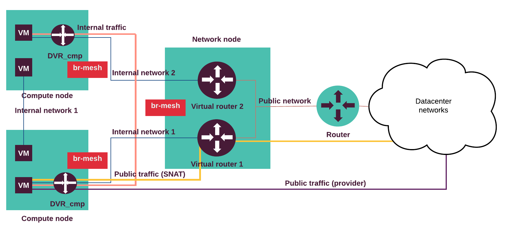
The internal traffic from one tenant virtual machine located on the virtual Internal network 1 goes to another virtual machine located in the Internal network 2 through the DVRs on the compute nodes. The external traffic (SNAT) from a virtual machine goes through the Internal network 1 and the DVR on the compute node to the virtual router on the network node and through the Public network to the outside network. The external routable traffic from a virtual machine on the compute nodes goes through the Internal network 1 and the DVR on the compute node through the Control or Public network to the outside network.
Traffic flow examples:
- A virtual machine without a floating IP address sends traffic to a
destination outside the Public network (N-S). The Internal network 1
is connected to a public network through the Neutron router.
The virtual machine (VM) is connected to the Internal network 1.
- The VM sends traffic through the virtual router to the network node.
- The network node performs SNAT, de-encapsulates and forwards traffic to the public network’s external gateway router.
- Return path same.
- A virtual machine with a floating IP address sends traffic to a destination
outside the Public network (N-S). The compute node with a DVR hosting the
VM is connected to a public network. An Internal network 1 is connected to
the external network through the Neutron router. The VM is connected to the
Internal network 1.
- The VM sends traffic through the compute node DVR to a public network (egress).
- The compute node DVR performs SNAT, de-encapsulates and forwards traffic to the public network’s external gateway router.
- Return path (ingress) same (DNAT).
- A virtual machine on an internal (private, tenant) network sends traffic to
a destination IP address on a public (provider, externally routed) network
(E-W). The compute node with DVR hosting the VM is connected to the provider
network. The Internal network 1 is connected to the provider network
through the Neutron router. The VM is connected to the Internal network 1.
- The VM sends traffic through the compute node DVR to a destination IP on a public network.
- The compute node DVR de-encapsulates and forwards traffic to a public network (no NAT).
- Return path same.
- A virtual machine (VM1) sends traffic to another VM (VM2) located on
separate host(E-W).
The Internal network 1 is connected to the Internal network 2
through the Neutron router. The (VM1) is connected to the Internal network 1
and the VM2 is connected to the Internal network 2.
- The VM1 sends traffic to the VM2 through the compute node DVR.
- The DVR on the compute node hosting VM1 forwards encapsulated traffic to the DVR on the compute node hosting VM2.
- Return path same.
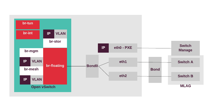
The compute nodes can access the external network,
therefore, there is the OVS bridge called br-floating.
All Open vSwitch bridges are automatically created by the Neutron
OVS agent. For a highly-available production environment, network
interface bonding is required.
The separation of the traffic types is done by the bonded tagged
sub-interfaces,
such as bond.x for the virtualized control plane traffic (management IP),
bond.y for the data plane bridge (br-mesh) that provides VTEP for
OVS, bond.z for storage, and others. The IP address of br-mesh is used
as a local IP in the openvswitch.ini configuration file for tunneling.
The following diagram displays the compute nodes configuration for the use case with Neutron VXLAN tenant networks with SNAT on the network nodes and external access on the compute and network nodes.