Virtualized control plane layout
Virtualized control plane layout
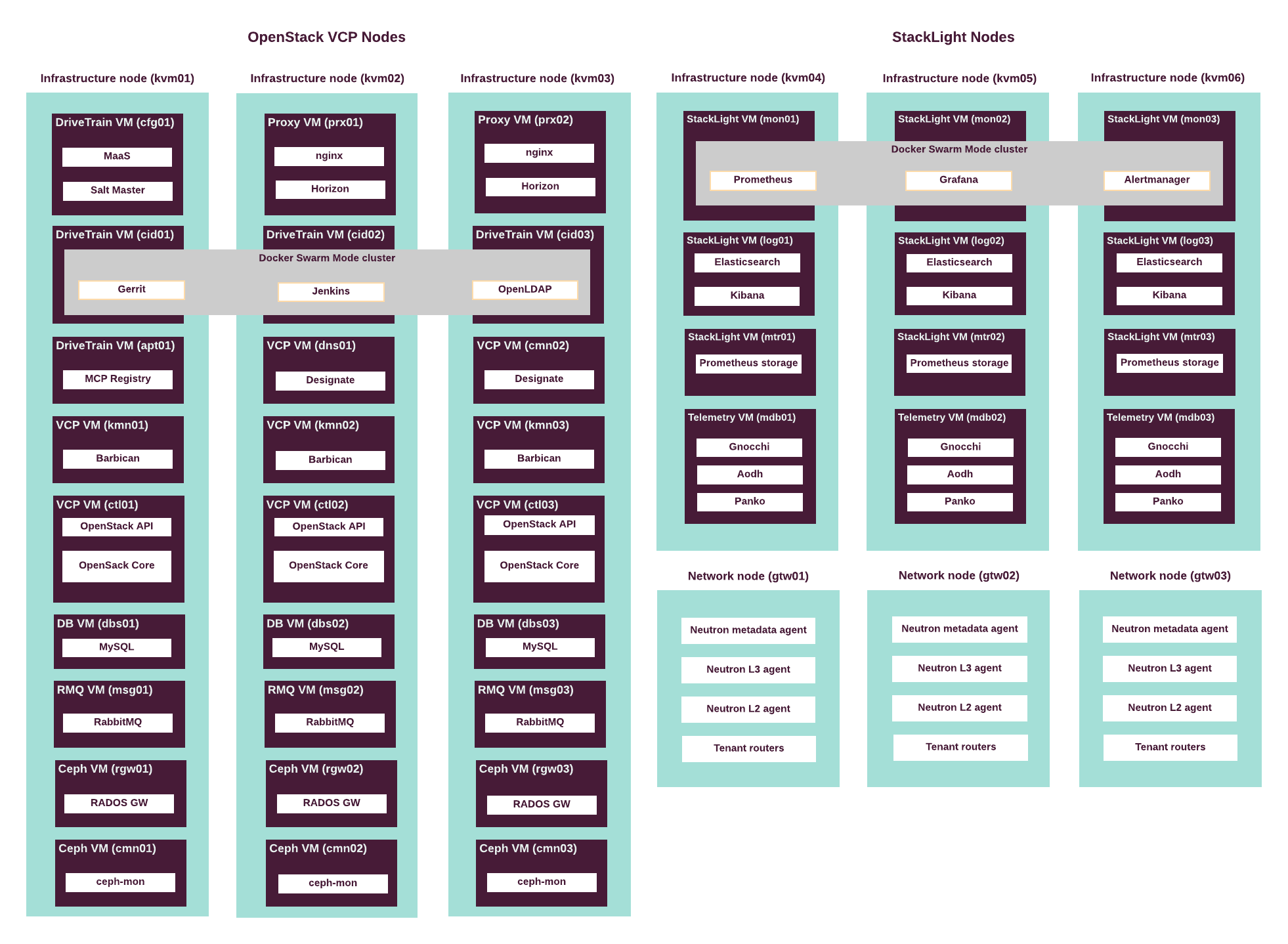
The following diagram describes the distribution of OpenStack and other services throughout the infrastructure nodes. For detailed description of the services, see Virtualized control plane.
The following table summarizes the VCP virtual machines mapped to physical servers. See Control plane virtual machines for details.
| Virtual server roles | Physical servers | # of instances | CPU vCores per instance | Memory (GB) per instance | Disk space (GB) per instance |
|---|---|---|---|---|---|
ctl |
kvm01 kvm02 kvm03 |
3 | 16 | 64 | 100 |
kmn |
kvm01 kvm02 kvm03 |
3 | 4 | 8 | 50 |
dns |
kvm02 kvm03 |
2 | 2 | 4 | 50 |
dbs |
kvm01 kvm02 kvm03 |
3 | 8 | 32 | 100 |
msg |
kvm01 kvm02 kvm03 |
3 | 16 | 64 | 100 |
prx |
kvm02 kvm03 |
2 | 4 | 16 | 300 |
cfg |
kvm01 |
1 | 8 | 16 | 50 |
cid |
kvm01 kvm02 kvm03 |
3 | 8 | 32 | 200 |
cmn |
kvm01 kvm02 kvm03 |
3 | 4 | 8 | 50 |
rgw |
kvm01 kvm02 kvm03 |
3 | 4 | 16 | 50 |
apt |
kvm01 |
1 | 4 | 16 | 500 |
mtr |
kvm04 kvm05 kvm06 |
3 | 12 | 96 | 1500 |
log |
kvm04 kvm05 kvm06 |
3 | 16 | 48 | 3000 |
mon |
kvm04 kvm05 kvm06 |
3 | 12 | 64 | 1000 |
mdb |
kvm04 kvm05 kvm06 |
3 | 8 | 32 | 500 |
MCP Ironic supported features and known limitations
View Previous Section
High availability in OpenStack