Mirantis Container Cloud (MCC) becomes part of Mirantis OpenStack for Kubernetes (MOSK)!
Starting with MOSK 25.2, the MOSK documentation set covers all product layers, including MOSK management (formerly Container Cloud). This means everything you need is in one place. Some legacy names may remain in the code and documentation and will be updated in future releases. The separate Container Cloud documentation site will be retired, so please update your bookmarks for continued easy access to the latest content.
Physical networks layout
This section summarizes the requirements for the physical layout of underlay network and VLANs configuration for the multi-rack architecture of Mirantis OpenStack for Kubernetes (MOSK).
Physical networking of a management cluster
Due to limitations of virtual IP address for Kubernetes API and of MetalLB load balancing in MOSK, the management cluster nodes must share VLAN segments in the provisioning and management networks.
In the multi-rack architecture, the management cluster nodes may be placed to a single rack or spread across three racks. In either case, provisioning and management network VLANs must be stretched across ToR switches of the racks.
Note
Since MOSK management 2.30.0, management cluster supports full L3 networking topology in the Technology Preview scope. This enables deployment of management cluster nodes in dedicated racks without the need for L2 layer extension between them.
For details, see Underlay networking: routing configuration.
The following diagram illustrates physical and L2 connections of a management cluster.
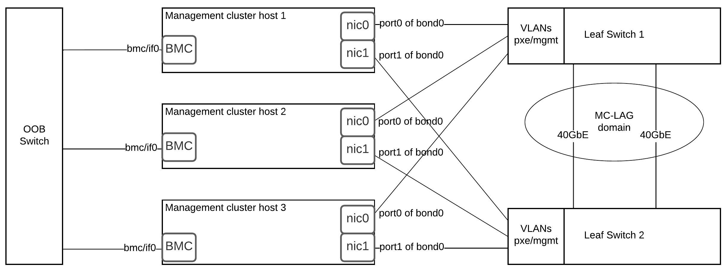
The network fabric reference configuration is a spine/leaf with 2 leaf ToR switches and one out-of-band (OOB) switch per rack.
Reference configuration uses the following switches for ToR and OOB:
Cisco WS-C3560E-24TD has 24 of 1 GbE ports. Used in OOB network segment.
Dell Force 10 S4810P has 48 of 1/10GbE ports. Used as ToR in Common/PXE network segment.
In the reference configuration, all odd interfaces from NIC0 are connected
to Leaf TOR Switch 1, and all even interfaces from NIC0 are connected
to Leaf TOR Switch 2. The Baseboard Management Controller (BMC) interfaces
of the servers are connected to OOB Switch 1.
The following recommendations apply to all types of nodes:
Use the Link Aggregation Control Protocol (LACP) bonding mode with MC-LAG domains configured on leaf switches. This corresponds to the
802.3adbond mode on hosts.Use ports from different multi-port NICs when creating bonds. This makes network connections redundant if failure of a single NIC occurs.
Configure the ports that connect servers to the PXE network with PXE VLAN as native or untagged. On these ports, configure LACP fallback to ensure that the servers can reach DHCP server and boot over network.
See also
Physical networking of a MOSK cluster
External network
Since 23.2.2, MOSK supports full L3 networking topology in the Technology Preview scope. This enables deployment of specific cluster segments in dedicated racks without the need for L2 layer extension between them. For configuration procedure, see Configure BGP announcement for cluster API LB address and Configure BGP announcement of external addresses of Kubernetes load-balanced services in Deployment Guide.
If you configure BGP announcement for IP addresses of load-balanced services of a MOSK cluster, the external network can consist of multiple VLAN segments connected to all nodes of a MOSK cluster where MetalLB speaker components are configured to announce IP addresses for Kubernetes load-balanced services. Mirantis recommends that you use OpenStack controller nodes for this purpose.
If you configure ARP announcement for IP addresses of load-balanced services of a MOSK cluster, the external network must consist of a single VLAN stretched to the ToR switches of all the racks where MOSK nodes connected to the external network are located. Those are the nodes where MetalLB speaker components are configured to announce IP addresses for Kubernetes load-balanced services. Mirantis recommends that you use OpenStack controller nodes for this purpose.
Depending of cluster needs, an operator can select how the VIP address for Kubernetes API is advertised. When BGP advertisement is used or the OpenStack control plane is deployed on separate nodes, as opposite to a compact control plane, it allows for a more flexible configuration and there is no need to search for a compromise such as the one described below.
But, when using ARP advertisement on a compact control plane, the selection of network for advertising the VIP address for Kubernetes API may depend on whether the symmetry of service return traffic is required. Therefore, when using ARP advertisement on a compact control plane, select one of the following options in the drop-down list:
Network selection for advertising the VIP address for Kubernetes
API on a compact control plane
For traffic symmetry between MOSK and management clusters and asymmetry in case of external clients:
Use the API/LCM network to advertise the VIP address for Kubernetes API. Allocate this VIP address in the CIDR address of the API/LCM network.
The gateway in the API/LCM network for a MOSK cluster must have a route to the management subnet of the management cluster. This is required to ensure symmetric traffic flow between the management and MOSK clusters.
For traffic symmetry in case of external clients and asymmetry between MOSK and management clusters:
Use external network to advertise the VIP address for Kubernetes API. Allocate this VIP address in the CIDR address of the external network.
One of the gateways either in the API/LCM network, or in the external network for a MOSK cluster must have a route to the management subnet of the management cluster. This is required to establish the traffic flow between the management and MOSK clusters.
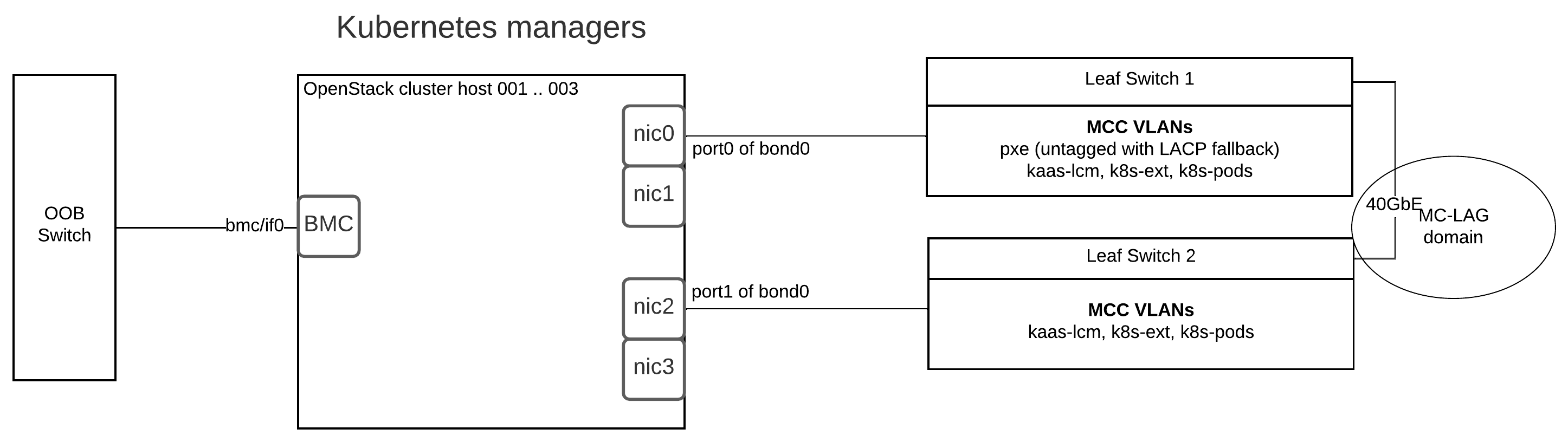
Kubernetes manager nodes
Note
Since 23.2.2, MOSK supports full L3 networking topology in the Technology Preview scope. This enables deployment of specific cluster segments in dedicated racks without the need for L2 layer extension between them. For configuration procedure, see Configure BGP announcement for cluster API LB address and Configure BGP announcement of external addresses of Kubernetes load-balanced services in Deployment Guide.
If BGP announcement is configured for MOSK cluster API LB address, Kubernetes manager nodes have no requirement to share the single stretched VLAN segment in the API/LCM network. All VLANs may be configured per rack.
If ARP announcement is configured for MOSK cluster API LB address, Kubernetes manager nodes must share the VLAN segment in the API/LCM network. In the multi-rack architecture, Kubernetes manager nodes may be spread across three racks. The API/LCM network VLAN must be stretched to the ToR switches of the racks. All other VLANs may be configured per rack. This requirement is caused by the Mirantis Kubernetes Engine underlay for MOSK relying on the Layer 2 VRRP protocol to ensure high availability of the Kubernetes API endpoint.
The following diagram illustrates physical and L2 network connections of the Kubernetes manager nodes in a MOSK cluster.
Caution
Such configuration does not apply to a compact control plane MOSK installation. See Create a MOSK cluster.
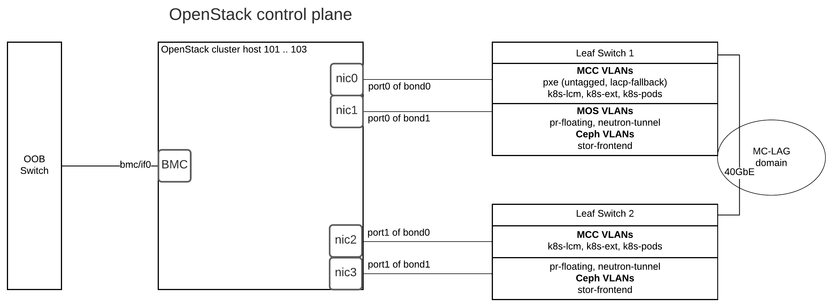
OpenStack controller nodes
The following diagram illustrates physical and L2 network connections of the control plane nodes in a MOSK cluster.
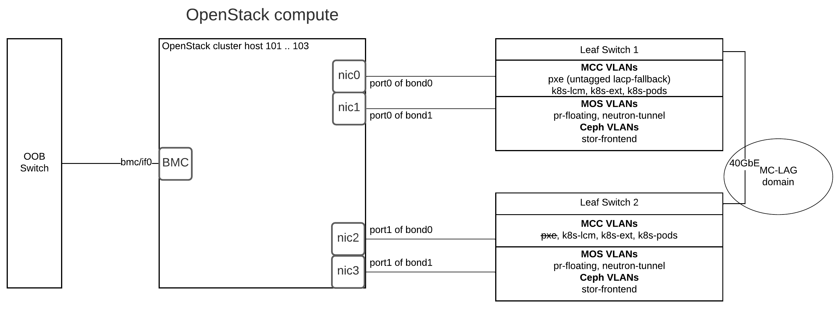
OpenStack compute nodes
All VLANs for OpenStack compute nodes may be configured per rack. No VLAN should be stretched across multiple racks.
The following diagram illustrates physical and L2 network connections of the compute nodes in a MOSK cluster.
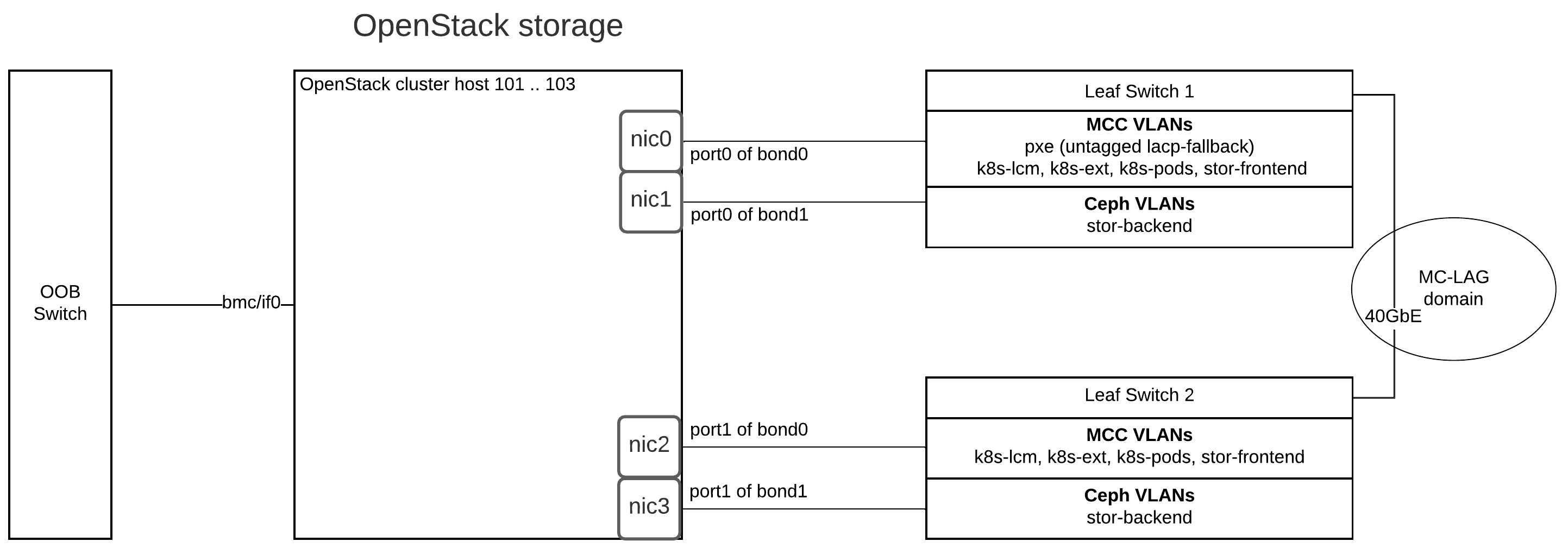
OpenStack storage nodes
All VLANs for OpenStack storage nodes may be configured per rack. No VLAN should be stretched across multiple racks.
The following diagram illustrates physical and L2 network connections of the storage nodes in a MOSK cluster.